Download to read offline
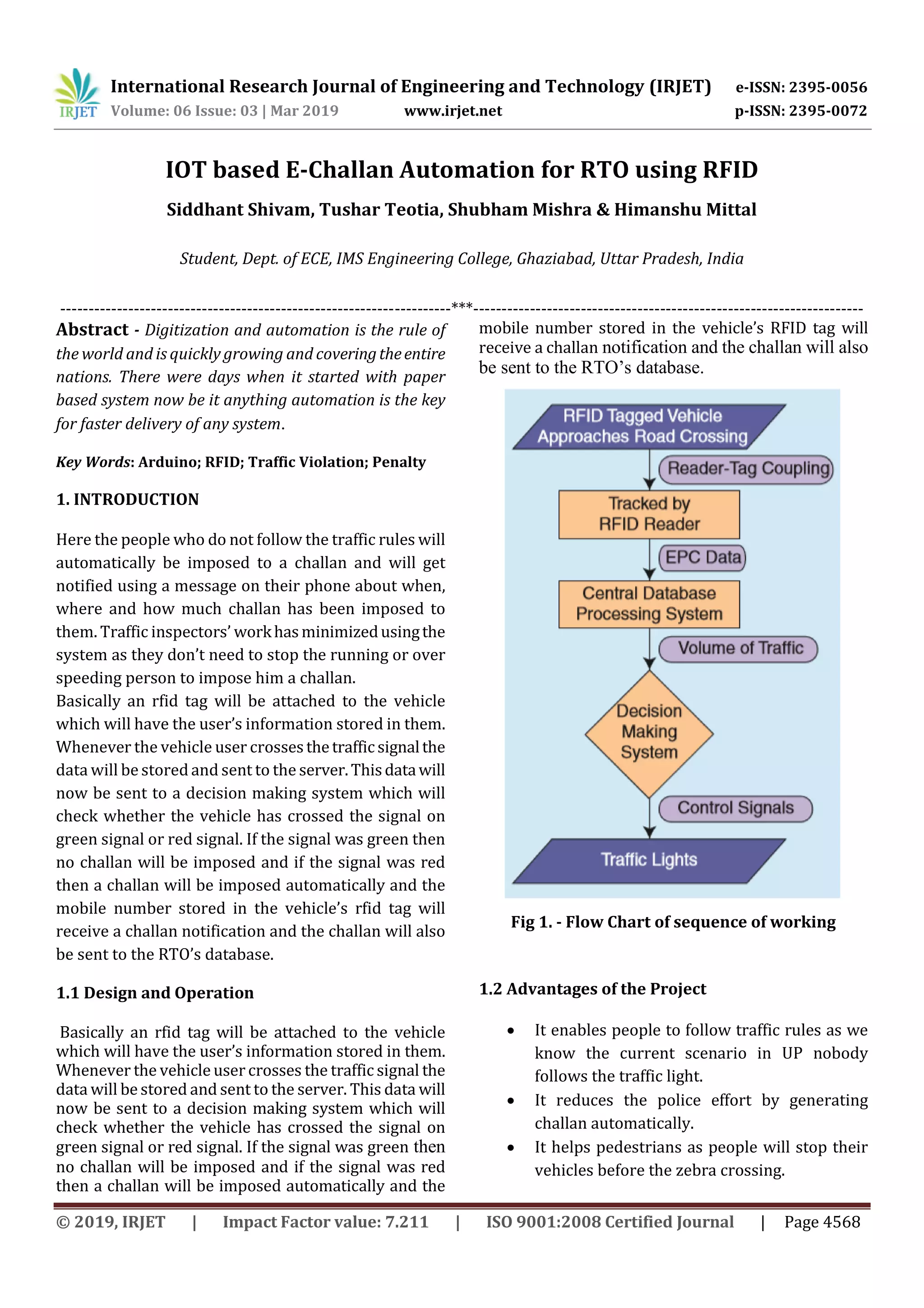
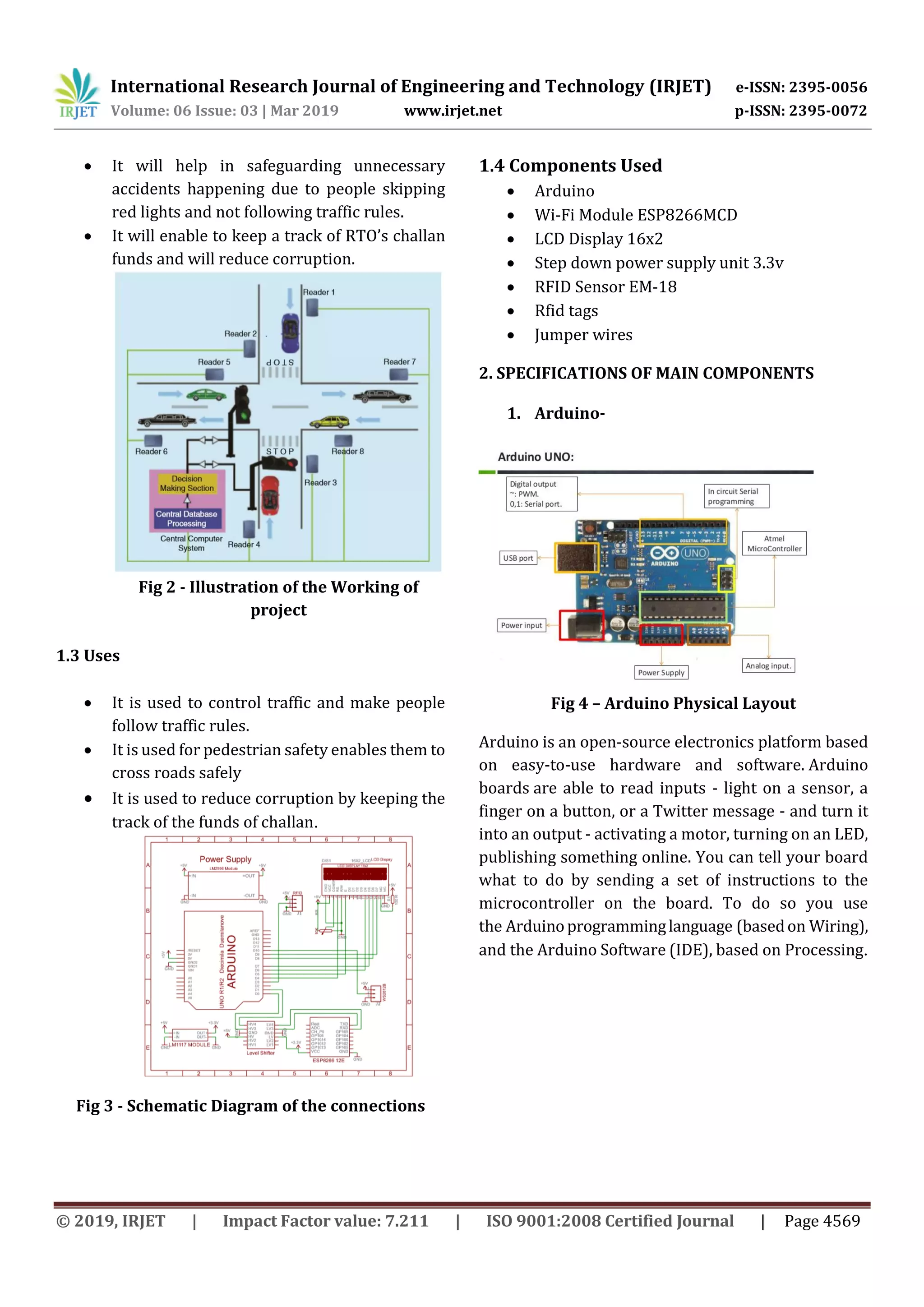


This document proposes an IOT-based system to automate traffic violation detection and e-challaning using RFID. The system would attach RFID tags to vehicles containing owner details. Sensors at traffic signals would detect if vehicles cross red lights and automatically issue e-challans by SMS, updating the RTO database. This would minimize manual enforcement efforts, encourage following traffic rules, and reduce corruption by tracking penalty collection. The system aims to increase road safety by automatically penalizing traffic violators.