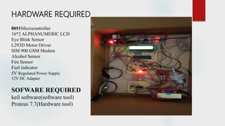
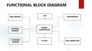
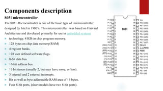
DROWSY DRIVER DETECTION SYSTEM
BY,
MUNEENDRA
AIM
The main aim of this is to develop a drowsiness detection system by
monitoring the eyes, the symptoms of driver fatigue can be detected
early enough to avoid a vehicle accident.
ABSTRACT
Vehicle accidents are most common if the driving is inadequate. These happen on most
factors if the driver is drowsy or if he is alcoholic. Driver drowsiness is recognized as
an important factor which leads to enormous fatal accidents. The driver loses his control when
he falls asleep which leads to accidents. It was demonstrated that driving performance
deteriorates with increased drowsiness with resulting crashes constituting more than 20% of
all vehicle accidents. But the life lost once cannot be re-winded. Advanced technology offers
some hope avoid these up to some extent.
PLAN OF ACTION:
The primary purpose of drowsy driver detection system is to develop a system that can reduce a
number of accidents from sleep driving of vehicle. For the detection stage the eye blink sensor
always monitor the eye blink moments, If the monitoring is over, the collected data will be
transmitted to a microcontroller, and a microcontroller digitizes the analog data. if warning
feedback is triggered, the microcontroller makes a decision, which alert needs to be activated.
This project involves measure and controls the eye blink using IR sensor. The IR transmitter is
used to transmit the infrared rays in our eye. The IR receiver is used to receive the reflected
infrared rays of eye. If the eye is closed means the output of IR receiver is high otherwise the IR
receiver output is low. This to know the eye is closing or opening position. This output is give to
logic circuit to indicate the alarm. This project helps in controlling accidents due to
unconsciousness through Eye blink.
The second application of this project is to detect the alcohol content or any smoke from the
vehicle.
CONTENTS:
 ABSTRACT
 INTRODUCTION
 HARDWARE AND SOFTWARE
 FUNCTIONAL BLOCK DIAGRAM
 COMPONENTS DESCRIPTION
 ADVANTAGES
 CONCLUSION
HARDWARE REQUIRED
8051Microcontroller
16*2 ALPHANUMERIC LCD
Eye Blink Sensor
L293D Motor Driver
SIM 900 GSM Modem
Alcohol Sensor
Fire Sensor
Fuel indicator
5V Regulated Power Supply
12V DC Adapter
SOFWARE REQUIRED
keil software(software tool)
Proteus 7.7(Hardware tool)
FUNCTIONAL BLOCK DIAGRAM
MICRO
CONTROLLER
LCD
FIRE SENSOR
ALCOHOL
SENSOR
EYE BLINK
SENSOR
GSM MODEM
FUEL INDIACTOR5V RPS
Components description
8051 microcontroller
The 8051 Microcontroller is one of the basic type of microcontroller,
designed by Intel in 1980’s. This microcontroller was based on Harvard
Architecture and developed primarily for use in embedded systems
 technology. 4 KB on chip program memory.
 128 bytes on chip data memory(RAM)
 4 register banks.
 128 user defined software flags.
 8-bit data bus
 16-bit address bus
 16 bit timers (usually 2, but may have more, or less).
 3 internal and 2 external interrupts.
 Bit as well as byte addressable RAM area of 16 bytes.
 Four 8-bit ports, (short models have two 8-bit ports).
16*2 LCD(LIQUID CRYSTAL DISPLAY)
our LCD is a 16*2 Dot matrix LCD and so it will have
(16*2=32) 32 characters in total and each character
will be made of 5*8 Pixel Dots.
Vss, Vdd, Vo are meant for the power supply
RS(REGISTER SELECT SIGNAL):Selects command register when low,
and data register when high.
R/W(READ/WRITE SELECT): Low to write to the register; High to read
from the register
ENABLE: Usually, we make it enable =0 and when we want to execute
the instruction we make it high enable=1 for some milli seconds. After this we again make it ground that is,
enable=0.
(DB0-DB3): four low order bit bidirectional three state data bus lines.
(DB4-DB7): four high order bit bidirectional three state data bus lines.
EYEBLINK SENSOR
The linking of eye is necessary in this project, since it is used to drive the
device and operate the events. This Eye Blink sensor is IR based which
consists of IR transmitter, The Variation Across the eye will vary as per
eye blink . If the eye is closed means the output is high otherwise output is low.
The signal is given to IR transmitter whenever the signal is high, the IR sensor
is conducting it passes the IR rays to the receiver. The IR receiver is connected to
the comparator, The comparator is connected with the operational amplifier.
The reference voltage is given to the inverting input, and the non-inverting is
given to the IR receiver.This to know the eye is closing or opening position.
This output is give to logic circuit to indicate through a message.
L293D Motor Driver
 L293D is a typical Motor driver or Motor Driver IC which allows DC motor to drive on
either direction. L293D is a 16-pin IC which can control a set of two DC motors simultaneously in
any direction. It means that you can control two DC motor with a single L293D IC.
 It works on the concept of H-bridge. H-bridge is a circuit which allows the voltage to be flown in
either direction. As you know voltage need to change its direction for being able to rotate the
motor in clockwise or anticlockwise direction, Hence H-bridge IC are ideal for driving a DC motor.

SIM 900 GSM MODEM:
This is a GSM/GPRS-compatible Quad-band cell phone, which works on a frequency of
850/900/1800/1900MHz and which can be used not only to
access the Internet, but also for oral communication
ALCOHOL SENSOR:
An alcohol sensor detects the attentiveness of alcohol gas in the air And an analog voltage is an output
reading.it is a sensitive device with a quick time response.
FIRE SENSOR: A flame detector is a sensor designed to detect and respond to the presence of
a flame or fire, allowing flame detection.
Advantages:
 light weight code , Simple method.
 Can work in dark, uses eyebrows monitoring.
 Easy implementation due to readily available hardware and
software.
 An efficient system to identify user attentiveness based on fatigue
detection.
CONCLUSION
About 20% of road accidents occur due to distraction of driver. Among that 30% is
due to driver fatigue. There are many methods to monitor driver and there by alert
him/her in case of distraction.
In order to reduce road accidents there is also a need to detect the causes such as
drowsiness, fatigue and to alert the driver. This survey enables to choose an efficient
method to reduce road accidents due to driver fatigue.
APPLICATIONS
This can be implemented in any four wheeler vehicles
THANKYOU

Drowsy Driver detection system

  • 1.
    DROWSY DRIVER DETECTIONSYSTEM BY, MUNEENDRA
  • 2.
    AIM The main aimof this is to develop a drowsiness detection system by monitoring the eyes, the symptoms of driver fatigue can be detected early enough to avoid a vehicle accident.
  • 3.
    ABSTRACT Vehicle accidents aremost common if the driving is inadequate. These happen on most factors if the driver is drowsy or if he is alcoholic. Driver drowsiness is recognized as an important factor which leads to enormous fatal accidents. The driver loses his control when he falls asleep which leads to accidents. It was demonstrated that driving performance deteriorates with increased drowsiness with resulting crashes constituting more than 20% of all vehicle accidents. But the life lost once cannot be re-winded. Advanced technology offers some hope avoid these up to some extent.
  • 4.
    PLAN OF ACTION: Theprimary purpose of drowsy driver detection system is to develop a system that can reduce a number of accidents from sleep driving of vehicle. For the detection stage the eye blink sensor always monitor the eye blink moments, If the monitoring is over, the collected data will be transmitted to a microcontroller, and a microcontroller digitizes the analog data. if warning feedback is triggered, the microcontroller makes a decision, which alert needs to be activated. This project involves measure and controls the eye blink using IR sensor. The IR transmitter is used to transmit the infrared rays in our eye. The IR receiver is used to receive the reflected infrared rays of eye. If the eye is closed means the output of IR receiver is high otherwise the IR receiver output is low. This to know the eye is closing or opening position. This output is give to logic circuit to indicate the alarm. This project helps in controlling accidents due to unconsciousness through Eye blink. The second application of this project is to detect the alcohol content or any smoke from the vehicle.
  • 5.
    CONTENTS:  ABSTRACT  INTRODUCTION HARDWARE AND SOFTWARE  FUNCTIONAL BLOCK DIAGRAM  COMPONENTS DESCRIPTION  ADVANTAGES  CONCLUSION
  • 6.
    HARDWARE REQUIRED 8051Microcontroller 16*2 ALPHANUMERICLCD Eye Blink Sensor L293D Motor Driver SIM 900 GSM Modem Alcohol Sensor Fire Sensor Fuel indicator 5V Regulated Power Supply 12V DC Adapter SOFWARE REQUIRED keil software(software tool) Proteus 7.7(Hardware tool)
  • 7.
    FUNCTIONAL BLOCK DIAGRAM MICRO CONTROLLER LCD FIRESENSOR ALCOHOL SENSOR EYE BLINK SENSOR GSM MODEM FUEL INDIACTOR5V RPS
  • 8.
    Components description 8051 microcontroller The8051 Microcontroller is one of the basic type of microcontroller, designed by Intel in 1980’s. This microcontroller was based on Harvard Architecture and developed primarily for use in embedded systems  technology. 4 KB on chip program memory.  128 bytes on chip data memory(RAM)  4 register banks.  128 user defined software flags.  8-bit data bus  16-bit address bus  16 bit timers (usually 2, but may have more, or less).  3 internal and 2 external interrupts.  Bit as well as byte addressable RAM area of 16 bytes.  Four 8-bit ports, (short models have two 8-bit ports).
  • 9.
    16*2 LCD(LIQUID CRYSTALDISPLAY) our LCD is a 16*2 Dot matrix LCD and so it will have (16*2=32) 32 characters in total and each character will be made of 5*8 Pixel Dots. Vss, Vdd, Vo are meant for the power supply RS(REGISTER SELECT SIGNAL):Selects command register when low, and data register when high. R/W(READ/WRITE SELECT): Low to write to the register; High to read from the register ENABLE: Usually, we make it enable =0 and when we want to execute the instruction we make it high enable=1 for some milli seconds. After this we again make it ground that is, enable=0. (DB0-DB3): four low order bit bidirectional three state data bus lines. (DB4-DB7): four high order bit bidirectional three state data bus lines.
  • 10.
    EYEBLINK SENSOR The linkingof eye is necessary in this project, since it is used to drive the device and operate the events. This Eye Blink sensor is IR based which consists of IR transmitter, The Variation Across the eye will vary as per eye blink . If the eye is closed means the output is high otherwise output is low. The signal is given to IR transmitter whenever the signal is high, the IR sensor is conducting it passes the IR rays to the receiver. The IR receiver is connected to the comparator, The comparator is connected with the operational amplifier. The reference voltage is given to the inverting input, and the non-inverting is given to the IR receiver.This to know the eye is closing or opening position. This output is give to logic circuit to indicate through a message.
  • 11.
    L293D Motor Driver L293D is a typical Motor driver or Motor Driver IC which allows DC motor to drive on either direction. L293D is a 16-pin IC which can control a set of two DC motors simultaneously in any direction. It means that you can control two DC motor with a single L293D IC.  It works on the concept of H-bridge. H-bridge is a circuit which allows the voltage to be flown in either direction. As you know voltage need to change its direction for being able to rotate the motor in clockwise or anticlockwise direction, Hence H-bridge IC are ideal for driving a DC motor. 
  • 12.
    SIM 900 GSMMODEM: This is a GSM/GPRS-compatible Quad-band cell phone, which works on a frequency of 850/900/1800/1900MHz and which can be used not only to access the Internet, but also for oral communication ALCOHOL SENSOR: An alcohol sensor detects the attentiveness of alcohol gas in the air And an analog voltage is an output reading.it is a sensitive device with a quick time response. FIRE SENSOR: A flame detector is a sensor designed to detect and respond to the presence of a flame or fire, allowing flame detection.
  • 13.
    Advantages:  light weightcode , Simple method.  Can work in dark, uses eyebrows monitoring.  Easy implementation due to readily available hardware and software.  An efficient system to identify user attentiveness based on fatigue detection.
  • 14.
    CONCLUSION About 20% ofroad accidents occur due to distraction of driver. Among that 30% is due to driver fatigue. There are many methods to monitor driver and there by alert him/her in case of distraction. In order to reduce road accidents there is also a need to detect the causes such as drowsiness, fatigue and to alert the driver. This survey enables to choose an efficient method to reduce road accidents due to driver fatigue.
  • 15.
    APPLICATIONS This can beimplemented in any four wheeler vehicles
  • 16.