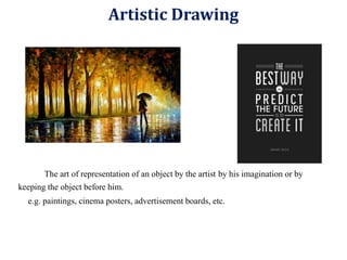
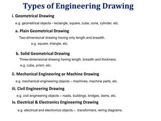
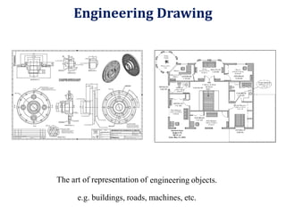
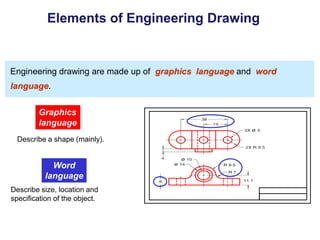
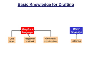
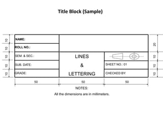
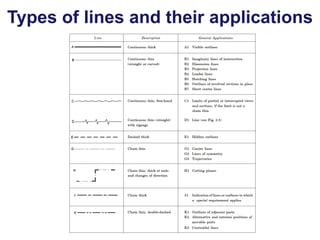
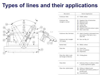
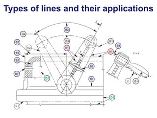
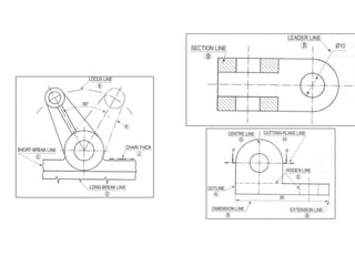
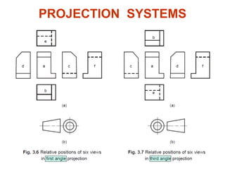
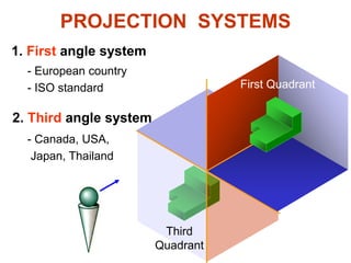
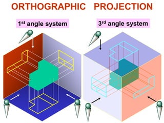
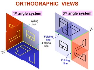
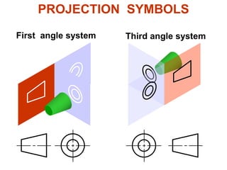
An engineering drawing clearly defines and communicates a design to interested parties through technical drawings rather than artistic depictions. It uses lines and geometric constructions to represent objects through projection methods in plan, elevation, and section views. Key elements of engineering drawings include types of lines, lettering, dimensioning, and projection systems like first-angle or third-angle orthographic projections. Precise graphics and annotations allow engineering drawings to effectively convey all necessary details of engineered components and assemblies.


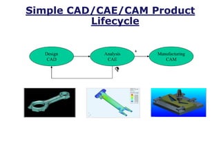


![W1-Introduction to ED [Autosaved].pptx](https://cdn.slidesharecdn.com/ss_thumbnails/w1-introductiontoedautosaved-221025152231-90341e07-thumbnail.jpg?width=640&height=640&fit=bounds)