Downloaded 333 times
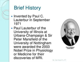
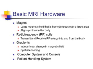
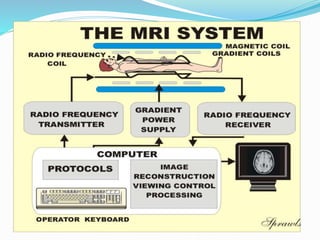
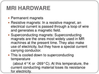
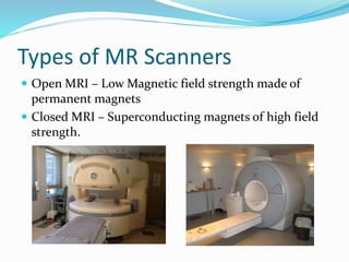
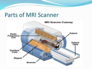
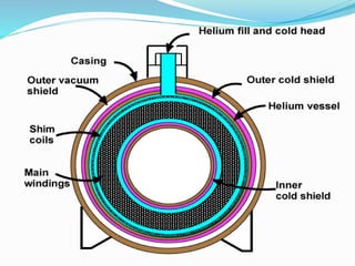
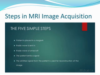
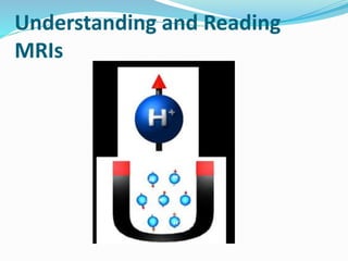
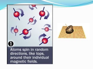
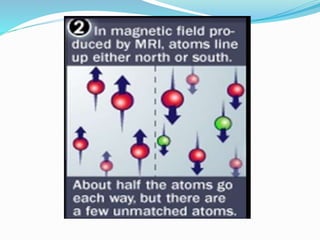
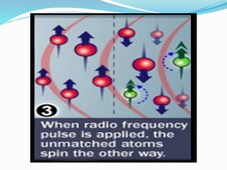
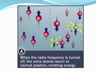
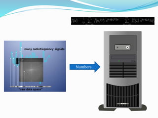
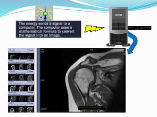

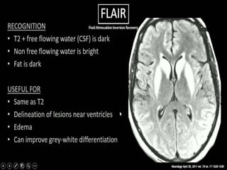
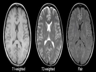
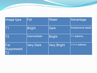
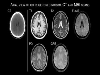
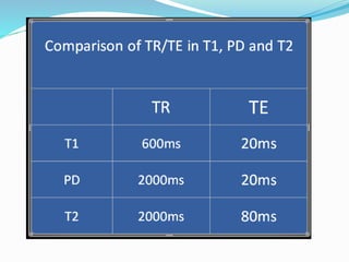
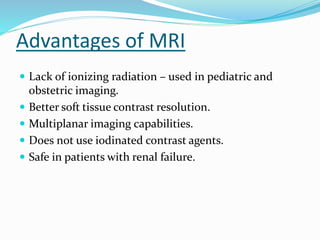
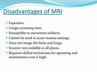
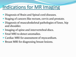
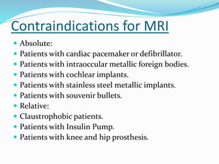
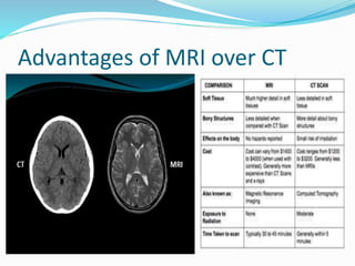

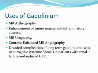

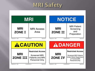
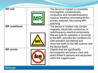
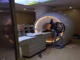
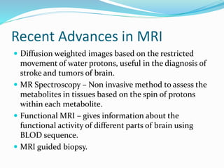
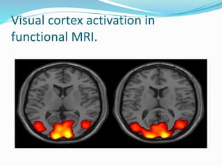


Dr. Rajesh Venunath Nair teaches radiology at K.S Hegde Medical Academy in Mangalore. His presentation discusses the history, basic principles, hardware, imaging sequences, and clinical applications of magnetic resonance imaging (MRI). It explains how MRI uses radiofrequency pulses and magnetic fields to produce detailed images of internal organs and soft tissues without using ionizing radiation. The presentation covers the main components of MRI scanners, different pulse sequences, tissue contrast mechanisms, use of contrast agents, safety considerations, and recent technical advances that have expanded clinical use of MRI.


![MAGNETIC_RESONANCE.._IMAGING[MRI][1].pptx](https://cdn.slidesharecdn.com/ss_thumbnails/magneticresonanceimagingmri1-240903182728-4f857936-thumbnail.jpg?width=640&height=640&fit=bounds)


![CASE_PRESENTATION_ON_subdural_hematoma(SDH)[1 FINAL PPT]-1.pptx](https://cdn.slidesharecdn.com/ss_thumbnails/casepresentationonsubduralhematomasdh1finalppt-1-260129172522-d405d375-thumbnail.jpg?width=640&height=640&fit=bounds)


