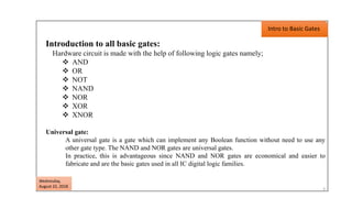
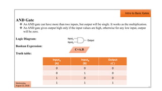
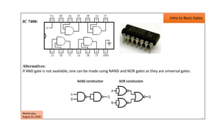
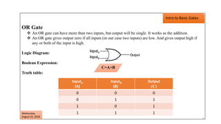
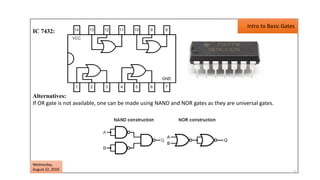
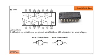
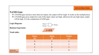
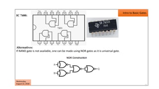
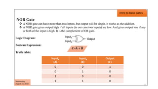
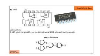
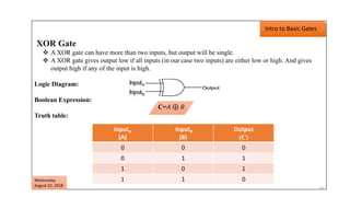
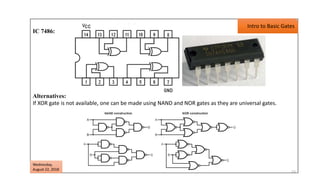
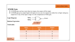
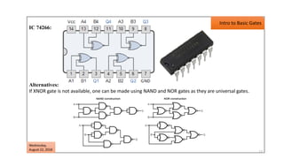
Digital Logic Design
By
Jalpa Maheshwari
1
What is DLD?
Digital logic design deals with
the basic concepts and tools to
design hardware consisting of
logic gates.
2
Wednesday,
August 22, 2018
Introduction to all basic gates:
Hardware circuit is made with the help of following logic gates namely;
 AND
 OR
 NOT
 NAND
 NOR
 XOR
 XNOR
Universal gate:
A universal gate is a gate which can implement any Boolean function without need to use any
other gate type. The NAND and NOR gates are universal gates.
In practice, this is advantageous since NAND and NOR gates are economical and easier to
fabricate and are the basic gates used in all IC digital logic families.
Intro to Basic Gates
3
Wednesday,
August 22, 2018
AND Gate
 An AND gate can have more than two inputs, but output will be single. It works as the multiplication.
 An AND gate gives output high only if the input values are high, otherwise for any low input, output
will be zero.
Logic Diagram:
Boolean Expression:
Truth table:
Intro to Basic Gates
InputA
(A)
InputB
(B)
Output
(C)
0 0 0
0 1 0
1 0 0
1 1 1
C=A.B
4
Wednesday,
August 22, 2018
5
IC 7408:
Alternatives:
If AND gate is not available, one can be made using NAND and NOR gates as they are universal gates.
Wednesday,
August 22, 2018
Intro to Basic Gates
OR Gate
 An OR gate can have more than two inputs, but output will be single. It works as the addition.
 An OR gate gives output zero if all inputs (in our case two inputs) are low. And gives output high if
any or both of the input is high.
Logic Diagram:
Boolean Expression:
Truth table:
Intro to Basic Gates
InputA
(A)
InputB
(B)
Output
(C)
0 0 0
0 1 1
1 0 1
1 1 1
C=A+B
6
Wednesday,
August 22, 2018
7
IC 7432:
Alternatives:
If OR gate is not available, one can be made using NAND and NOR gates as they are universal gates.
Wednesday,
August 22, 2018
Intro to Basic Gates
NOT Gate
 NOT gate is also known as Inverter.
 If input is low, it gives high output and vice versa. In other words, it complements or inverts its input
signal.
Logic Diagram:
Boolean Expression:
Truth table:
Intro to Basic Gates
InputA
(A)
Output
( 𝐀)
0 1
1 0
A= 𝐀
8
Wednesday,
August 22, 2018
9
IC 7404:
Alternatives:
If NOT gate is not available, one can be made using NAND and NOR gates as they are universal gates.
Wednesday,
August 22, 2018
Intro to Basic Gates
NAND Gate
 A NAND gate can have more than two inputs, but output will be single. It works as the multiplication.
 A NAND gate gives output low only if the input values are high, otherwise for any high input, output
will be high. It is the complement of AND gate.
Logic Diagram:
Boolean Expression:
Truth table:
Intro to Basic Gates
InputA
(A)
InputB
(B)
Output
(C)
0 0 1
0 1 1
1 0 1
1 1 0
C=𝐀. 𝐁
10
Wednesday,
August 22, 2018
11
IC 7400:
Alternatives:
If NAND gate is not available, one can be made using NOR gates as it is universal gate.
Wednesday,
August 22, 2018
Intro to Basic Gates
NOR Gate
 A NOR gate can have more than two inputs, but output will be single. It works as the addition.
 A NOR gate gives output high if all inputs (in our case two inputs) are low. And gives output low if any
or both of the input is high. It is the complement of OR gate.
Logic Diagram:
Boolean Expression:
Truth table:
Intro to Basic Gates
InputA
(A)
InputB
(B)
Output
(C)
0 0 1
0 1 0
1 0 0
1 1 0
C=𝐀 + 𝐁
Wednesday,
August 22, 2018
12
13
IC 7402:
Alternatives:
If NOR gate is not available, one can be made using NAND gates as it is universal gate.
Wednesday,
August 22, 2018
Intro to Basic Gates
XOR Gate
 A XOR gate can have more than two inputs, but output will be single.
 A XOR gate gives output low if all inputs (in our case two inputs) are either low or high. And gives
output high if any of the input is high.
Logic Diagram:
Boolean Expression:
Truth table:
Intro to Basic Gates
InputA
(A)
InputB
(B)
Output
(C)
0 0 0
0 1 1
1 0 1
1 1 0
C=𝐴 ⊕ 𝐵
Wednesday,
August 22, 2018
14
15
IC 7486:
Alternatives:
If XOR gate is not available, one can be made using NAND and NOR gates as they are universal gates.
Wednesday,
August 22, 2018
Intro to Basic Gates
XNOR Gate
 A XNOR gate can have more than two inputs, but output will be single.
 A XNOR gate gives output high if all inputs (in our case two inputs) are either low or high. And gives
output low if any of the input is high. It is the complement of NOR gate.
Logic Diagram:
Boolean Expression:
Truth table:
Intro to Basic Gates
InputA
(A)
InputB
(B)
Output
(C)
0 0 1
0 1 0
1 0 0
1 1 1
C=𝐴 ⊕ 𝐵
16
Wednesday,
August 22, 2018
17
IC 74266:
Alternatives:
If XNOR gate is not available, one can be made using NAND and NOR gates as they are universal gates.
Wednesday,
August 22, 2018
Intro to Basic Gates
18

Digital Logic Design

  • 1.
  • 2.
    What is DLD? Digitallogic design deals with the basic concepts and tools to design hardware consisting of logic gates. 2 Wednesday, August 22, 2018
  • 3.
    Introduction to allbasic gates: Hardware circuit is made with the help of following logic gates namely;  AND  OR  NOT  NAND  NOR  XOR  XNOR Universal gate: A universal gate is a gate which can implement any Boolean function without need to use any other gate type. The NAND and NOR gates are universal gates. In practice, this is advantageous since NAND and NOR gates are economical and easier to fabricate and are the basic gates used in all IC digital logic families. Intro to Basic Gates 3 Wednesday, August 22, 2018
  • 4.
    AND Gate  AnAND gate can have more than two inputs, but output will be single. It works as the multiplication.  An AND gate gives output high only if the input values are high, otherwise for any low input, output will be zero. Logic Diagram: Boolean Expression: Truth table: Intro to Basic Gates InputA (A) InputB (B) Output (C) 0 0 0 0 1 0 1 0 0 1 1 1 C=A.B 4 Wednesday, August 22, 2018
  • 5.
    5 IC 7408: Alternatives: If ANDgate is not available, one can be made using NAND and NOR gates as they are universal gates. Wednesday, August 22, 2018 Intro to Basic Gates
  • 6.
    OR Gate  AnOR gate can have more than two inputs, but output will be single. It works as the addition.  An OR gate gives output zero if all inputs (in our case two inputs) are low. And gives output high if any or both of the input is high. Logic Diagram: Boolean Expression: Truth table: Intro to Basic Gates InputA (A) InputB (B) Output (C) 0 0 0 0 1 1 1 0 1 1 1 1 C=A+B 6 Wednesday, August 22, 2018
  • 7.
    7 IC 7432: Alternatives: If ORgate is not available, one can be made using NAND and NOR gates as they are universal gates. Wednesday, August 22, 2018 Intro to Basic Gates
  • 8.
    NOT Gate  NOTgate is also known as Inverter.  If input is low, it gives high output and vice versa. In other words, it complements or inverts its input signal. Logic Diagram: Boolean Expression: Truth table: Intro to Basic Gates InputA (A) Output ( 𝐀) 0 1 1 0 A= 𝐀 8 Wednesday, August 22, 2018
  • 9.
    9 IC 7404: Alternatives: If NOTgate is not available, one can be made using NAND and NOR gates as they are universal gates. Wednesday, August 22, 2018 Intro to Basic Gates
  • 10.
    NAND Gate  ANAND gate can have more than two inputs, but output will be single. It works as the multiplication.  A NAND gate gives output low only if the input values are high, otherwise for any high input, output will be high. It is the complement of AND gate. Logic Diagram: Boolean Expression: Truth table: Intro to Basic Gates InputA (A) InputB (B) Output (C) 0 0 1 0 1 1 1 0 1 1 1 0 C=𝐀. 𝐁 10 Wednesday, August 22, 2018
  • 11.
    11 IC 7400: Alternatives: If NANDgate is not available, one can be made using NOR gates as it is universal gate. Wednesday, August 22, 2018 Intro to Basic Gates
  • 12.
    NOR Gate  ANOR gate can have more than two inputs, but output will be single. It works as the addition.  A NOR gate gives output high if all inputs (in our case two inputs) are low. And gives output low if any or both of the input is high. It is the complement of OR gate. Logic Diagram: Boolean Expression: Truth table: Intro to Basic Gates InputA (A) InputB (B) Output (C) 0 0 1 0 1 0 1 0 0 1 1 0 C=𝐀 + 𝐁 Wednesday, August 22, 2018 12
  • 13.
    13 IC 7402: Alternatives: If NORgate is not available, one can be made using NAND gates as it is universal gate. Wednesday, August 22, 2018 Intro to Basic Gates
  • 14.
    XOR Gate  AXOR gate can have more than two inputs, but output will be single.  A XOR gate gives output low if all inputs (in our case two inputs) are either low or high. And gives output high if any of the input is high. Logic Diagram: Boolean Expression: Truth table: Intro to Basic Gates InputA (A) InputB (B) Output (C) 0 0 0 0 1 1 1 0 1 1 1 0 C=𝐴 ⊕ 𝐵 Wednesday, August 22, 2018 14
  • 15.
    15 IC 7486: Alternatives: If XORgate is not available, one can be made using NAND and NOR gates as they are universal gates. Wednesday, August 22, 2018 Intro to Basic Gates
  • 16.
    XNOR Gate  AXNOR gate can have more than two inputs, but output will be single.  A XNOR gate gives output high if all inputs (in our case two inputs) are either low or high. And gives output low if any of the input is high. It is the complement of NOR gate. Logic Diagram: Boolean Expression: Truth table: Intro to Basic Gates InputA (A) InputB (B) Output (C) 0 0 1 0 1 0 1 0 0 1 1 1 C=𝐴 ⊕ 𝐵 16 Wednesday, August 22, 2018
  • 17.
    17 IC 74266: Alternatives: If XNORgate is not available, one can be made using NAND and NOR gates as they are universal gates. Wednesday, August 22, 2018 Intro to Basic Gates
  • 18.