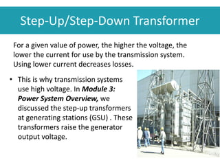
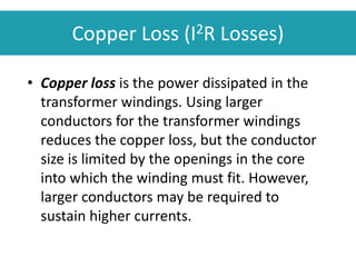
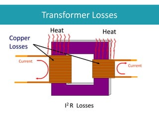
This document provides an overview of transformer principles and operation. It discusses how transformers work by using mutual induction between two coils to change voltage levels. Key points covered include transformer components, turns ratio, step-up and step-down functions, efficiency losses, tap changing, and three-phase configurations. Transformer types like power, distribution, instrument and phase shifting transformers are also summarized.
FellowBuddy.com is a platform which has been setup with a simple vision, keeping in mind the dynamic requirements of students.
Our Vision & Mission - Simplifying Students Life
Our Belief - “The great breakthrough in your life comes when you realize it, that you can learn anything you need to learn; to accomplish any goal that you have set for yourself. This means there are no limits on what you can be, have or do.”
Like Us - https://www.facebook.com/FellowBuddycom-446240585585480
Alternating Current -12 isc 2017 ( investigatory Project) Student
In this file, we will study about the various types of ac circuits, how they work,their phasor diagrams,types of periodic form,analytical method and graphical method to find average value of alternating current.
Step-down transformer Physics project Class 12 CBSE FinalMuhammad Jassim
FULL MARK WITH THIS. EASY NO WORY. QUESTIONS FOR VIVA WILL ALSO BE EASY SINCE THE PROJECT IS EASY.
Step-down transformer Physics project Class 12 CBSE Final
Transformers (Especially For 12th Std)Atit Gaonkar
It Is The One Which Will Help A Student To Recall or Study about Transformer.
The Principle, Constructions, Working, Ideal Transformer, Leakages, Efficiency, Cores, Related Solved Problems. etc. are readily available in this power-point.
COLLEGE BUS MANAGEMENT SYSTEM PROJECT REPORT.pdfKamal Acharya
The College Bus Management system is completely developed by Visual Basic .NET Version. The application is connect with most secured database language MS SQL Server. The application is develop by using best combination of front-end and back-end languages. The application is totally design like flat user interface. This flat user interface is more attractive user interface in 2017. The application is gives more important to the system functionality. The application is to manage the student’s details, driver’s details, bus details, bus route details, bus fees details and more. The application has only one unit for admin. The admin can manage the entire application. The admin can login into the application by using username and password of the admin. The application is develop for big and small colleges. It is more user friendly for non-computer person. Even they can easily learn how to manage the application within hours. The application is more secure by the admin. The system will give an effective output for the VB.Net and SQL Server given as input to the system. The compiled java program given as input to the system, after scanning the program will generate different reports. The application generates the report for users. The admin can view and download the report of the data. The application deliver the excel format reports. Because, excel formatted reports is very easy to understand the income and expense of the college bus. This application is mainly develop for windows operating system users. In 2017, 73% of people enterprises are using windows operating system. So the application will easily install for all the windows operating system users. The application-developed size is very low. The application consumes very low space in disk. Therefore, the user can allocate very minimum local disk space for this application.
Event Management System Vb Net Project Report.pdfKamal Acharya
In present era, the scopes of information technology growing with a very fast .We do not see any are untouched from this industry. The scope of information technology has become wider includes: Business and industry. Household Business, Communication, Education, Entertainment, Science, Medicine, Engineering, Distance Learning, Weather Forecasting. Carrier Searching and so on.
My project named “Event Management System” is software that store and maintained all events coordinated in college. It also helpful to print related reports. My project will help to record the events coordinated by faculties with their Name, Event subject, date & details in an efficient & effective ways.
In my system we have to make a system by which a user can record all events coordinated by a particular faculty. In our proposed system some more featured are added which differs it from the existing system such as security.
Automobile Management System Project Report.pdfKamal Acharya
The proposed project is developed to manage the automobile in the automobile dealer company. The main module in this project is login, automobile management, customer management, sales, complaints and reports. The first module is the login. The automobile showroom owner should login to the project for usage. The username and password are verified and if it is correct, next form opens. If the username and password are not correct, it shows the error message.
When a customer search for a automobile, if the automobile is available, they will be taken to a page that shows the details of the automobile including automobile name, automobile ID, quantity, price etc. “Automobile Management System” is useful for maintaining automobiles, customers effectively and hence helps for establishing good relation between customer and automobile organization. It contains various customized modules for effectively maintaining automobiles and stock information accurately and safely.
When the automobile is sold to the customer, stock will be reduced automatically. When a new purchase is made, stock will be increased automatically. While selecting automobiles for sale, the proposed software will automatically check for total number of available stock of that particular item, if the total stock of that particular item is less than 5, software will notify the user to purchase the particular item.
Also when the user tries to sale items which are not in stock, the system will prompt the user that the stock is not enough. Customers of this system can search for a automobile; can purchase a automobile easily by selecting fast. On the other hand the stock of automobiles can be maintained perfectly by the automobile shop manager overcoming the drawbacks of existing system.
Immunizing Image Classifiers Against Localized Adversary Attacksgerogepatton
This paper addresses the vulnerability of deep learning models, particularly convolutional neural networks
(CNN)s, to adversarial attacks and presents a proactive training technique designed to counter them. We
introduce a novel volumization algorithm, which transforms 2D images into 3D volumetric representations.
When combined with 3D convolution and deep curriculum learning optimization (CLO), itsignificantly improves
the immunity of models against localized universal attacks by up to 40%. We evaluate our proposed approach
using contemporary CNN architectures and the modified Canadian Institute for Advanced Research (CIFAR-10
and CIFAR-100) and ImageNet Large Scale Visual Recognition Challenge (ILSVRC12) datasets, showcasing
accuracy improvements over previous techniques. The results indicate that the combination of the volumetric
input and curriculum learning holds significant promise for mitigating adversarial attacks without necessitating
adversary training.
Courier management system project report.pdfKamal Acharya
It is now-a-days very important for the people to send or receive articles like imported furniture, electronic items, gifts, business goods and the like. People depend vastly on different transport systems which mostly use the manual way of receiving and delivering the articles. There is no way to track the articles till they are received and there is no way to let the customer know what happened in transit, once he booked some articles. In such a situation, we need a system which completely computerizes the cargo activities including time to time tracking of the articles sent. This need is fulfilled by Courier Management System software which is online software for the cargo management people that enables them to receive the goods from a source and send them to a required destination and track their status from time to time.
Welcome to WIPAC Monthly the magazine brought to you by the LinkedIn Group Water Industry Process Automation & Control.
In this month's edition, along with this month's industry news to celebrate the 13 years since the group was created we have articles including
A case study of the used of Advanced Process Control at the Wastewater Treatment works at Lleida in Spain
A look back on an article on smart wastewater networks in order to see how the industry has measured up in the interim around the adoption of Digital Transformation in the Water Industry.
TECHNICAL TRAINING MANUAL GENERAL FAMILIARIZATION COURSEDuvanRamosGarzon1
AIRCRAFT GENERAL
The Single Aisle is the most advanced family aircraft in service today, with fly-by-wire flight controls.
The A318, A319, A320 and A321 are twin-engine subsonic medium range aircraft.
The family offers a choice of engines
Student information management system project report ii.pdfKamal Acharya
Our project explains about the student management. This project mainly explains the various actions related to student details. This project shows some ease in adding, editing and deleting the student details. It also provides a less time consuming process for viewing, adding, editing and deleting the marks of the students.
NO1 Uk best vashikaran specialist in delhi vashikaran baba near me online vas...Amil Baba Dawood bangali
Contact with Dawood Bhai Just call on +92322-6382012 and we'll help you. We'll solve all your problems within 12 to 24 hours and with 101% guarantee and with astrology systematic. If you want to take any personal or professional advice then also you can call us on +92322-6382012 , ONLINE LOVE PROBLEM & Other all types of Daily Life Problem's.Then CALL or WHATSAPP us on +92322-6382012 and Get all these problems solutions here by Amil Baba DAWOOD BANGALI
#vashikaranspecialist #astrologer #palmistry #amliyaat #taweez #manpasandshadi #horoscope #spiritual #lovelife #lovespell #marriagespell#aamilbabainpakistan #amilbabainkarachi #powerfullblackmagicspell #kalajadumantarspecialist #realamilbaba #AmilbabainPakistan #astrologerincanada #astrologerindubai #lovespellsmaster #kalajaduspecialist #lovespellsthatwork #aamilbabainlahore#blackmagicformarriage #aamilbaba #kalajadu #kalailam #taweez #wazifaexpert #jadumantar #vashikaranspecialist #astrologer #palmistry #amliyaat #taweez #manpasandshadi #horoscope #spiritual #lovelife #lovespell #marriagespell#aamilbabainpakistan #amilbabainkarachi #powerfullblackmagicspell #kalajadumantarspecialist #realamilbaba #AmilbabainPakistan #astrologerincanada #astrologerindubai #lovespellsmaster #kalajaduspecialist #lovespellsthatwork #aamilbabainlahore #blackmagicforlove #blackmagicformarriage #aamilbaba #kalajadu #kalailam #taweez #wazifaexpert #jadumantar #vashikaranspecialist #astrologer #palmistry #amliyaat #taweez #manpasandshadi #horoscope #spiritual #lovelife #lovespell #marriagespell#aamilbabainpakistan #amilbabainkarachi #powerfullblackmagicspell #kalajadumantarspecialist #realamilbaba #AmilbabainPakistan #astrologerincanada #astrologerindubai #lovespellsmaster #kalajaduspecialist #lovespellsthatwork #aamilbabainlahore #Amilbabainuk #amilbabainspain #amilbabaindubai #Amilbabainnorway #amilbabainkrachi #amilbabainlahore #amilbabaingujranwalan #amilbabainislamabad
Explore the innovative world of trenchless pipe repair with our comprehensive guide, "The Benefits and Techniques of Trenchless Pipe Repair." This document delves into the modern methods of repairing underground pipes without the need for extensive excavation, highlighting the numerous advantages and the latest techniques used in the industry.
Learn about the cost savings, reduced environmental impact, and minimal disruption associated with trenchless technology. Discover detailed explanations of popular techniques such as pipe bursting, cured-in-place pipe (CIPP) lining, and directional drilling. Understand how these methods can be applied to various types of infrastructure, from residential plumbing to large-scale municipal systems.
Ideal for homeowners, contractors, engineers, and anyone interested in modern plumbing solutions, this guide provides valuable insights into why trenchless pipe repair is becoming the preferred choice for pipe rehabilitation. Stay informed about the latest advancements and best practices in the field.
1. Course Outline
1. Introduction to WECC
2. Fundamentals of Electricity
3. Power System Overview
4. Principles of Generation
5. Substation Overview
6. Transformers
7. Power Transmission
8. System Protection
9. Principles of System Operation
2. Module Overview
• This module presents the following topics:
• Principle of Operation
• Types of Transformers
• Operating Considerations and Limitations
3. Principle of Operation
• The purpose of a transformer is to change an
electric system quantity (e.g., voltage or
current) from one level to another.
• A transformer is made up of two or more
conductors wound around a single magnetic
core, usually iron. The wound conductors,
usually copper, are called windings.
4. Two-Winding Transformer
The primary winding is electrically connected to the power source.
The secondary winding is electrically connected to the energy output or load side.
There is no electrical connection between the primary and secondary windings.
5. Tertiary Winding
• Sometimes a third winding, the tertiary winding,
is present. A tertiary winding provides power to
an auxiliary circuit or a reactor.
• The core and the windings are mounted in a steel
tank filled with mineral oil or some other liquid
suitable for insulating and cooling. Insulated
bushings, usually mounted at the top of the tank,
connect the windings to other power system
equipment.
6. How do Transformers Work?
• Passing an alternating current through a coil causes an
alternating magnetic flux in the magnetic core.
• The magnetic flux circulates in the magnetic core,
passing through another coil (the secondary winding),
inducing an alternating voltage in this coil.
• The amount of induced voltage depends upon four
factors:
– 1) core composition and shape
– 2) number of turns in primary coil or winding
– 3) number of turns in the secondary coil or winding
– 4) primary voltage
7. In a transformer there are two or more coils linked together by a common
core conducting the magnetic flux. Flux from one coil (the primary winding)
passes through the other coil (the secondary winding), inducing a voltage in
the secondary winding. Mutual induction links the two windings.
How do Transformers Work?
8. Turns Ratio
• At the beginning of this section, we state that the
transformer's purpose is to change an electric
system quantity from one level to another. The
amount a quantity changes is determined by the
turns ratio, which is the ratio of the number of
turns in the two windings.
• The magnetic flux links the turns of the primary
and secondary windings. This induces a voltage
in each winding. Since the same flux cuts both
windings, the same voltage is induced in each
turn of both windings.
9. Turns Ratio
• The total voltage in each winding is
proportional to the number of turns
in that winding:
V1 ÷ V2 = N1 ÷ N2
• V1 and V2 are the voltages in the primary and secondary
windings, respectively.
• N1 and N2 are the number of turns in the primary and
secondary windings, respectively.
10. Turns Ratio
• We know from Module 2 that inductance is the
electrical circuit property that opposes the change of
current. The following statements describe the
relationship between flux and inductance:
– Increasing the current flow increases the magnitude
of the flux.
– Increasing the turns in the conductor increases the
concentration of flux.
– Increasing the flux concentration increases induction.
– Inductance causes the current to lag the voltage. The
current may lag the voltage in a transformer by a
maximum of 90○.
11. • V1= Primary Volts
• V2= Secondary Volts
• N1= Primary Turns
• N2= Secondary Turns
Turns Ratio
• I1= Primary Current
• I2= Secondary Current
• P1= Primary Power In
• P2= Secondary Pwr Out
There is one additional relationship we must consider – the relationship
between P1 and P2. In an ideal transformer, the power into the
transformer is equal to the power out of the transformer. In other words,
there are no losses.
Therefore, the following relationship exists: P1 = P2
Using the relationships, we can determine the changes across a
transformer.
13. Step-Up Transformer
500 turns
1:10 24,000 volts2400 volts
1000 A 100 A
1
10
=
EP
ES
1
10
=
IS
IP
NP
NS
=
50
500
=
1
10
50 turns
Source
Load
14. Determining Output Voltage
• Let's apply these relationships to an example:
• A transformer has 300 turns on its primary winding
and 600 turns on its secondary winding. The input
voltage is 120 volts. What is the output voltage?
• The given quantities are:
• V1 = 120 volts
• N1 = 300 turns
• N2 = 600 turns
15. Determining Output Current
• If we are given I1, we can determine the secondary
current, I2, by using the following equation:
If I1 = 800 amps, by substituting the given values
into the equation we have:
16. Determining Power
• Remember, the power remains the same across
the transformer. So, let's check to make sure the
power into the transformer is the same as the
power coming out of the transformer. (For
purposes of this example, assume a resistive
load; therefore, cos θ = 1)
• P1 = V1 x I1 x cos θ
• P1 = 120 V x 800 A x 1
• P1 = 96,000 Watts
• P1 = 96 kW
17. • P2 should be the same. Let's see.
• P2 = V2 x I2 x cos θ
• P2 = 240 V x 400 A x 1
• P2 = 96,000 Watts
• P2 = 96 kW
• These calculations show that the power on the
primary side of the transformer equals the
power on the secondary side of the transformer.
Determining Power
18. Step-Up/Step-Down Transformer
• In the example, the transformer changed the
primary-side voltage from 120 V to a secondary
voltage of 240 V to decrease the current on the
secondary side. This is an example of a step-up
transformer; the voltage was stepped up from
120 V to 240 V. Conversely, a transformer in
which the energy transfer is from a high-voltage
circuit to a low-voltage circuit is a step-down
transformer.
19. • We can see from the example that whatever happens
to the voltage through the transformer, the opposite
happens to the current.
– If the voltage is stepped down, current is stepped up by
the same ratio.
– Likewise, when voltage is stepped up, current is stepped
down by the same ratio.
• Some important concepts to remember about
transformers include:
– Transformers do not produce electricity. They only
transform it from one level to another; i.e., step the
voltage or current up or down.
Step-Up/Step-Down Transformer
20. • Although transformers take certain levels of
voltage and current and change them to other
levels, the total amount of power does not
change from one side of the transformer to the
other, if losses are ignored.
• The power on the primary side equals the power
on the secondary side, if the transformer is
without losses. In reality, transformers
experience some losses. We discuss losses later
in this module.
Step-Up/Step-Down Transformer
21. • This is why transmission systems
use high voltage. In Module 3:
Power System Overview, we
discussed the step-up transformers
at generating stations (GSU) . These
transformers raise the generator
output voltage.
Step-Up/Step-Down Transformer
For a given value of power, the higher the voltage, the
lower the current for use by the transmission system.
Using lower current decreases losses.
22. • While the transformer is operating, some
electrical energy is converted into heat. But
we know the purpose of the transformer is
not to provide heat. The purpose is to transfer
electrical energy from the primary to the
secondary winding. Therefore, any heat the
transformer produces is an energy loss and
represents inefficiency.
Step-Up/Step-Down Transformer
23. Transformer Efficiency
• The efficiency of a transformer is the ratio of
the output power to the input power.
But we stated earlier that the power into a transformer is
equal to the power out of the transformer, therefore the
efficiency equals 100%. This is the ideal case. In reality, the
transformer consumes some of the power. Most
transformers have an efficiency of between 97% and 99%.
24. Losses
• The power consumed is called power loss. It is
caused by the following:
– hysteresis losses
– eddy current losses
– copper (I2R) losses
• Hysteresis and eddy current losses occur in the
transformer's core.
• Copper losses occur in the windings.
• All three loss types involve the conversion of
electrical energy into heat energy.
25. Residual Magnetism
• Hysteresis loss is due to residual magnetism, which is
the magnetism that remains in a material after the
magnetizing force is removed. The transformer core
reverses magnetic polarity each time the primary
current reverses direction. Every time the magnetic
polarity reverses, the residual magnetism of the previous
polarity has to be overcome. This produces heat.
Hysteresis loss is the energy required to reduce the
residual magnetism to zero and occurs every half cycle
just before the core is re-magnetized in the opposite
direction.
27. • Eddy current is the current that flows in the
transformer's core and results from the voltage that is
induced in the core by the primary winding. We know
that the primary coil creates a flux that induces a
voltage in the secondary coil. The flux also cuts the
core, and we know that when a varying flux passes
through a conductor it induces voltage. The core is
itself a conductor. So a voltage is induced in the core
as well as in the secondary winding. In the core, the
energy is converted to heat. Eddy current can be
reduced by laminating the transformer's core with a
higher resistance material.
Eddy Currents
29. Copper Loss (I2R Losses)
• Copper loss is the power dissipated in the
transformer windings. Using larger
conductors for the transformer windings
reduces the copper loss, but the conductor
size is limited by the openings in the core
into which the winding must fit. However,
larger conductors may be required to
sustain higher currents.
31. Voltage Control
• Most high-voltage transformers contain taps on the
windings for changing the transformer's turns ratio. A
tap is a connection at some point on a primary or
secondary winding which permits changing the turns
ratio. Changing the turns ratio alters the secondary
voltage and current.
• If the need for voltage adjustments is infrequent (e.g.,
adjustments are made for load growth or seasonal
variations), utilities use no load de-energized tap
changers. As the name implies, the transformer is de-
energized prior to changing taps.
33. Load Tap Changer
• Where frequent voltage adjustments are
necessary, or in cases of a transformer that
cannot be de-energized without jeopardizing
customer service, utilities use load-tap-changing
(LTC) transformers. LTC transformers, sometimes
called tap-changing under load (TCUL)
transformers, change transformer taps
automatically, remote manually via SCADA, or
manually by local control, while the transformer
is energized.
34. • The tap changer is operated by a motor that
responds to relay settings to hold the voltage at a
pre-determined level.
• Special circuits allow the tap to be changed
without interrupting current.
• The load-tap changing equipment is usually
housed in a separate compartment on the side of
the transformer. Load-tap changing equipment is
used on power transformers, autotransformers,
and distribution transformers.
Load Tap Changer
37. How Transformer Taps Adjust Voltage
Primary
Winding
Secondary Winding
Tap Changer
Taps
Changing taps adjusts the turns-
ratio between windings
voltage
38. • Up to this point we have been discussing single-phase
transformers.
• Three-phase transformers operate using the same
principles: passing an alternating current through a
primary winding causes an alternating magnetic flux in the
core, which induces an alternating voltage in the
secondary winding.
• In three-phase transformers there are three primary
windings and three secondary windings.
• Some three-phase transformers include windings for all
three phases in one tank.
• Other three-phase transformers have three single-phase
transformers connected together.
Three Phase Transformer
41. Transformer Bank
• The connection of two or more single-phase transformers as a unit
is called a transformer bank. The most common methods for
connecting the windings are:
– Wye or Y (sometimes called star) connection
– Delta connection
• We discussed the Wye and Delta connections in Module 2:
Fundamentals of Electricity. Some methods of connecting the
windings result in a voltage phase difference between the primary
and the secondary windings. This is called a phase shift. The
primary and secondary windings need not have the same
configuration.
44. • We must consider these phase shifts before
tying together circuits fed through different
types of transformers. For example,
connecting a circuit fed by a Wye-Delta bank
to a circuit fed by a Wye-Wye bank results in
excessive current flow because of the 30º
phase difference.
Transformer Connections
45. Types of Transformers
• Power Transformers
• Autotransformers
• Phase Shifting Transformers
• Instrument Transformers
• Distribution Transformers
46. Power Transformers
• Power transformer is a
term given to a
transformer used to
transfer power for
voltages higher than 69 kV.
Most power transformers
are three-phase. Power
transformers can step-up
or step-down the voltage.
Other capabilities can be
added to a step-up or
step-down transformer,
such as tap changing
equipment.
47. Autotransformers
• An autotransformer is a
single-winding transformer
with a terminal that divides
the winding into two
sections. Autotransformers
are useful because they are
simply constructed and
cost relatively little
compared with multi-
winding transformers.
• Autotransformers are
variously designed to raise
or lower the voltage at
• ± 5%, ± 7.5%, or ± 10 %
ranges.
49. Phase Shifting Transformers
• Phase shifting transformers,
sometimes called phase angle
regulators (PARS), control power
flow over parallel lines by
adjusting the voltage phase angle
at one end of the line.
• Phase shifting transformers
increase or decrease the phase
angle differences between buses.
Inserting a phase shifting
transformer on a transmission line
changes the power flow over the
line by changing the phase angle
between locations thus
redistributing the power flow.
51. Phase Shifting Transformers
• The Phase A series winding's secondary is connected to Phase B's
exciting winding.
• Phase B's voltage lags Phase A's voltage by 120º (or 60º leading if
the polarity is reversed).
• The Phase B exciting winding induces a voltage in the Phase A
series secondary winding. This small out-of-phase voltage advances
the supply voltage
52. Instrument Transformers
• In high-voltage systems, direct
measurement of voltage or current is not
practical. We must scale down the values
for use by meters and relays. Instrument
transformers perform this function.
• Instrument transformers include current
transformers (CTs) and potential
transformers (PTs) (sometimes called
voltage transformers [VTs]). Both of these
transformers reduce system current and
voltage to lower values for use by the
relays and control circuitry. We discuss
CTs and PTs in more detail in Module 8:
System Protection.
53. Distribution Transformers
• A distribution transformer reduces voltage to a level that is
usable by customers. Distribution transformers are mounted
on poles, on concrete pads, or in underground vaults. Their
operation is similar to a power transformer.
54. Transformer Cooling Systems
• Excessive heating in the transformer causes the
insulation to deteriorate; therefore, it is
important to prevent overheating. The
technology for this is based on the idea that oil
cools the core and windings. Transformer
manufacturers equip transformers with cooling
systems that prevent the permissible
temperature rise of the insulating oil from
exceeding specifications.
55. • Cooling systems for large power transformers
typically include:
– radiators in which outside air cools the
transformer oil that circulates by convection
through the radiators
– pumps to increase the circulation rate when
additional cooling is needed
– fans that blow air on the radiators for added
cooling
Transformer Cooling Systems
57. Transformer Ratings
• Heat generated within the transformer tank causes the
transformer insulation to deteriorate gradually. While
some heating is unavoidable, excessive heating can
cause rapid deterioration and breakdown of the
transformer insulating materials.
• The transformer rating is the maximum power that
the transformer can safely carry without exceeding a
temperature limit and is expressed in MVA.
Transformers typically have more than one rating
depending on the portion of the transformer cooling
system that is operating.
58. • The forced-oil and air (FOA) rating is the
maximum rating that applies when oil pumps
and cooling fans are operating.
• The forced air (FA) rating applies when the fans
are running but the oil pumps are not running
(oil is flowing by natural circulation). This is
approximately 80% of the maximum rating.
• The oil to air (OA) rating applies when neither
the fans nor the oil pumps are running. This is
approximately 60% of maximum rating.
Transformer Ratings
59. • It is important to detect faults in the
transformer windings before damage occurs.
Major problems that cause extensive damage
in transformers usually start out as small
short-circuits between turns. These short
circuits usually develop into an arc, which
produces large volumes of gas by chemically
decomposing the insulating oil.
Transformer Ratings
60. • Relays that detect rising internal gas pressure
in the tank are able to detect such faults while
they are still relatively minor. However, these
relays cannot be too sensitive, or they
operate needlessly for pressure surges caused
by sudden changes in current flow, such as
those caused by external faults.
Transformer Ratings
61. • It is important to be able to determine:
– whether a transformer relay operated incorrectly, in
which case the operator should restore the
transformer to service.
– whether there is a minor internal fault that should be
repaired prior to re-energizing the transformer to
prevent more extensive damage.
• Following a transformer relay operation,
substation personnel typically perform
inspections to determine whether an internal
short circuit is present.
Transformer Ratings
62. They may:
• Perform a resistance check to determine whether
normally energized parts have come in contact with
normally non-energized parts.
• Draw gas and oil samples from the tank and have
the samples analyzed to determine whether
excessive decomposition due to arcing has occurred.
• Measure the turns ratio to determine whether a
short circuit has occurred between turns.
Transformer Ratings
63. • If test results indicate that no internal fault exists,
the transformer can be re-energized.
• As a preventive measure, utilities periodically
inspect transformers to identify possible problems.
Most transformers include gauges for reading
transformer loading, oil levels and temperatures,
and gas pressures and temperatures to assist in
performing these inspections.
Transformer Ratings
64. So what happens when you exceed those
transformer ratings?
Transformer Ratings
65.
66.
67.
68.
69.
70.
71. Salem and Hope Creek Nuclear Power Stations, Hancock’s Bridge NJ