Download to read offline
![International Journal of Civil Engineering and Technology (IJCIET), ISSN 0976 – 6308 (Print),
ISSN 0976 – 6316(Online), Volume 6, Issue 5, May (2015), pp. 85-99 © IAEME
89
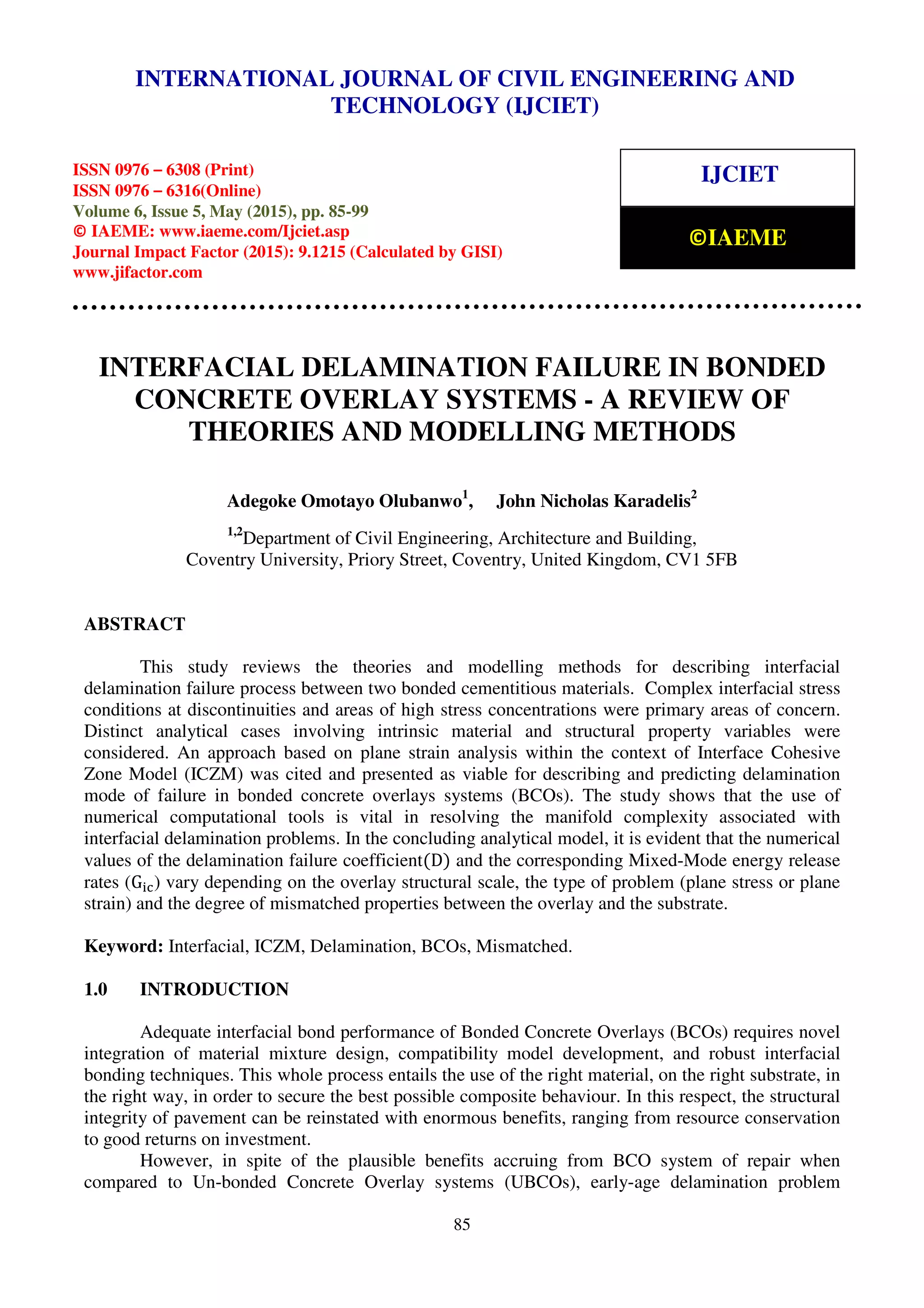
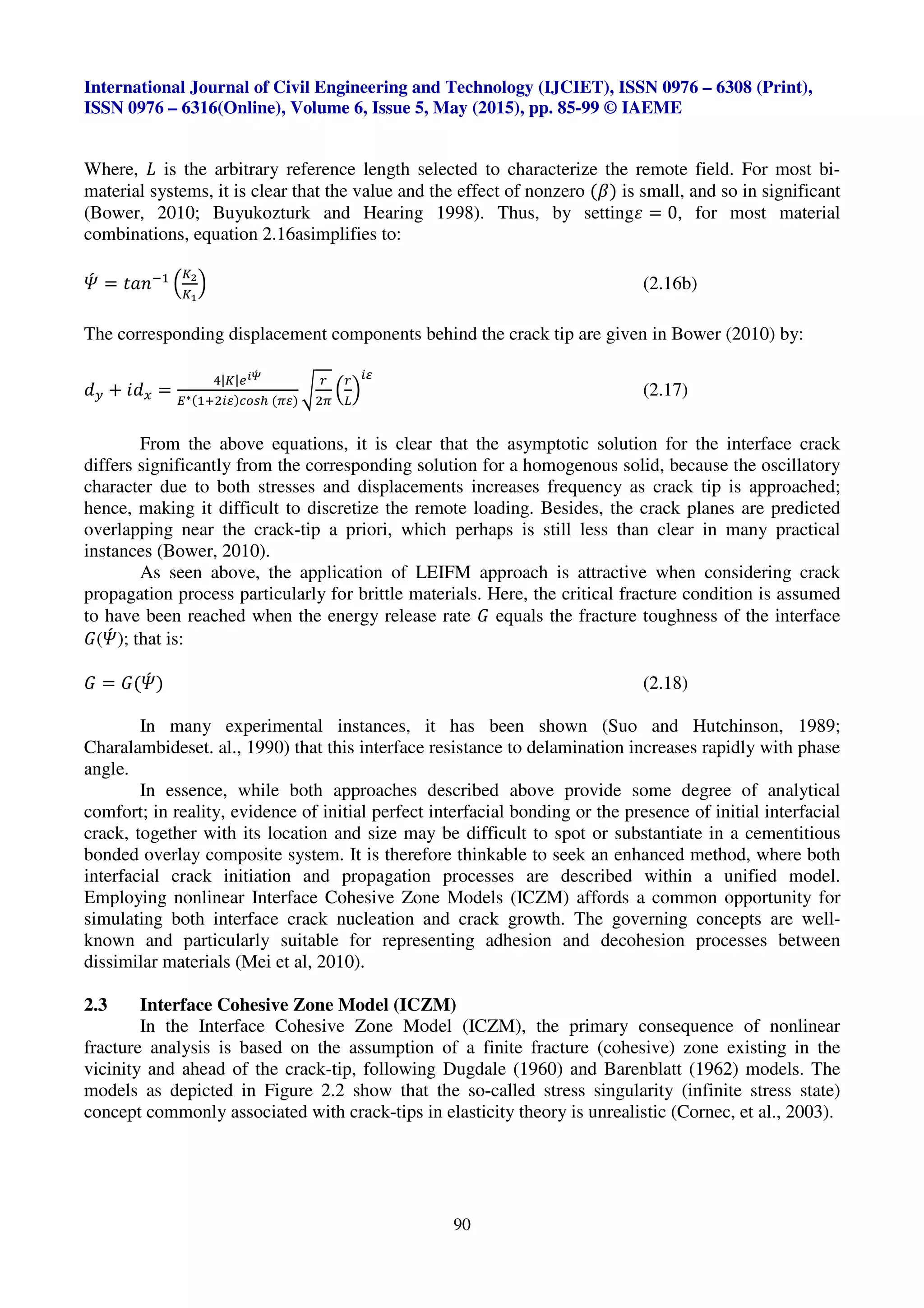
K< =
σ[ >(ε ? @ 3A).3ε > B (ε ? @3A)].Dτ[> B (ε ? @3A)E3ε > (ε ? @3A)]F
>G πε
√a (2.7)
K3 =
τ[ >(ε ? @3A).3ε > B (ε ? @3A)]EDσ[> B (ε ? @ 3A)E3ε > (ε ? @3A)]F
>G πε
√a (2.8)
From where, εisestimated as:
ε =
<
3π
In I
<Eβ
<.β
J (2.9)
In equation (2.9), (K)relates to one of Dundur’s elastic mismatched parameters (Dundur,
1969) which measures the relative compressibility of the two bonded materials, commonly estimated
from equation (2.10), say, for plane strain problems (Mei et. al, 2007); while its counterpart (L)given
in equation (2.11) measures the corresponding relative stiffness (Mei et. al, 2007; Schmauder,
1990;Bower, 2010).
K =
<
3
I
M-(<E3N/)EM/(<E3N-)
M-(<E N/).M/(< . N-)
J (2.10a)
Which on simplifying yields:
K =
O-
′ (<EN-)(<E3N/)EO/
′ (<E N/)(<E3N-)
3(<EN-)(<E N/)(O-
′ . O/
′ )
(2.10b)
Where,PQ
′
= PQ (1 − RQ
3
)⁄ TUVWX YZ[VWX ]^X_’Y `]a^U^Y b][ cVZd[WVU W
L =
O-
′ E O/
′
O-
′ . O/
′ (2.11)
Subsequently, under a Mixed-Mode fracture analysis, the energy release rate,(e), for crack
extension per unit length along the interface for plain strain is generally given by (Carlsson and
Prasad, 1993):
e =
|g|/
O∗ijkl/mn
(2.12)
Where,
|o| = 2o<
3
* o3
3
(2.13)
p]Yℎ3
rs = 1/(1 − K3
) (2.14)
<
O∗
=
<
3
u
<
O-
′ *
<
O/
′ v (2.15)
Thus, by Mode-Mixity, the value of(e) as a function of the loading phase angle(w)x follows
the real and imaginary stress intensity factors of the remote field lying ahead of the crack tip. This
phase angle is typically expressed as:
wx = ZVXE<
I
yz(g-.Qg/){|}
~•(g-.Qg/){|}
J (2.16a)](https://image.slidesharecdn.com/interfacialdelaminationfailureinbondedconcreteoverlaysystemsareviewoftheoriesandmodellingmethods-150820093153-lva1-app6892/75/Interfacial-delamination-failure-in-bonded-concrete-overlay-systems-a-review-of-theories-and-modelling-methods-5-2048.jpg)
![International Journal of Civil Engineering and Technology (IJCIET), ISSN 0976 – 6308 (Print),
ISSN 0976 – 6316(Online), Volume 6, Issue 5, May (2015), pp. 85-99 © IAEME
93
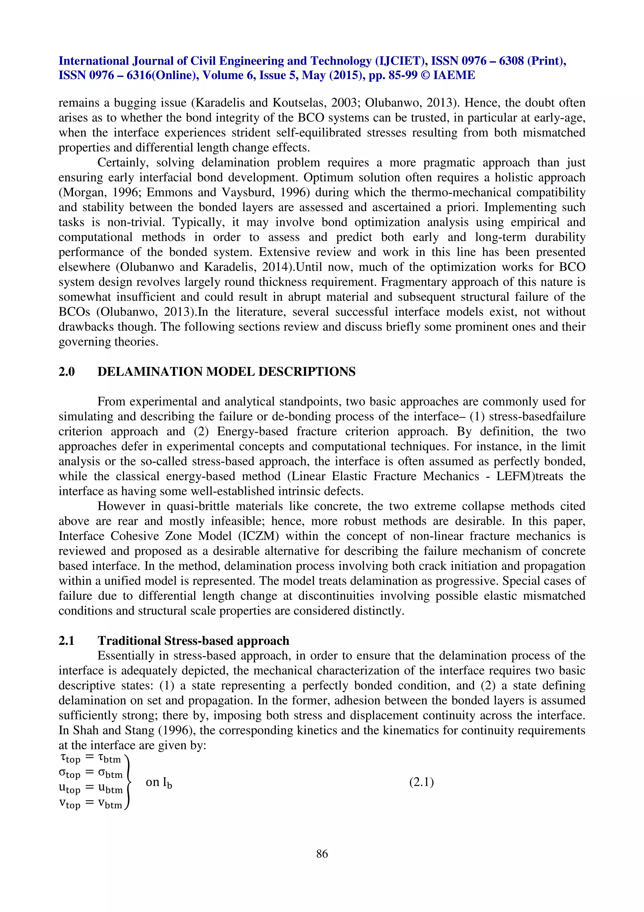
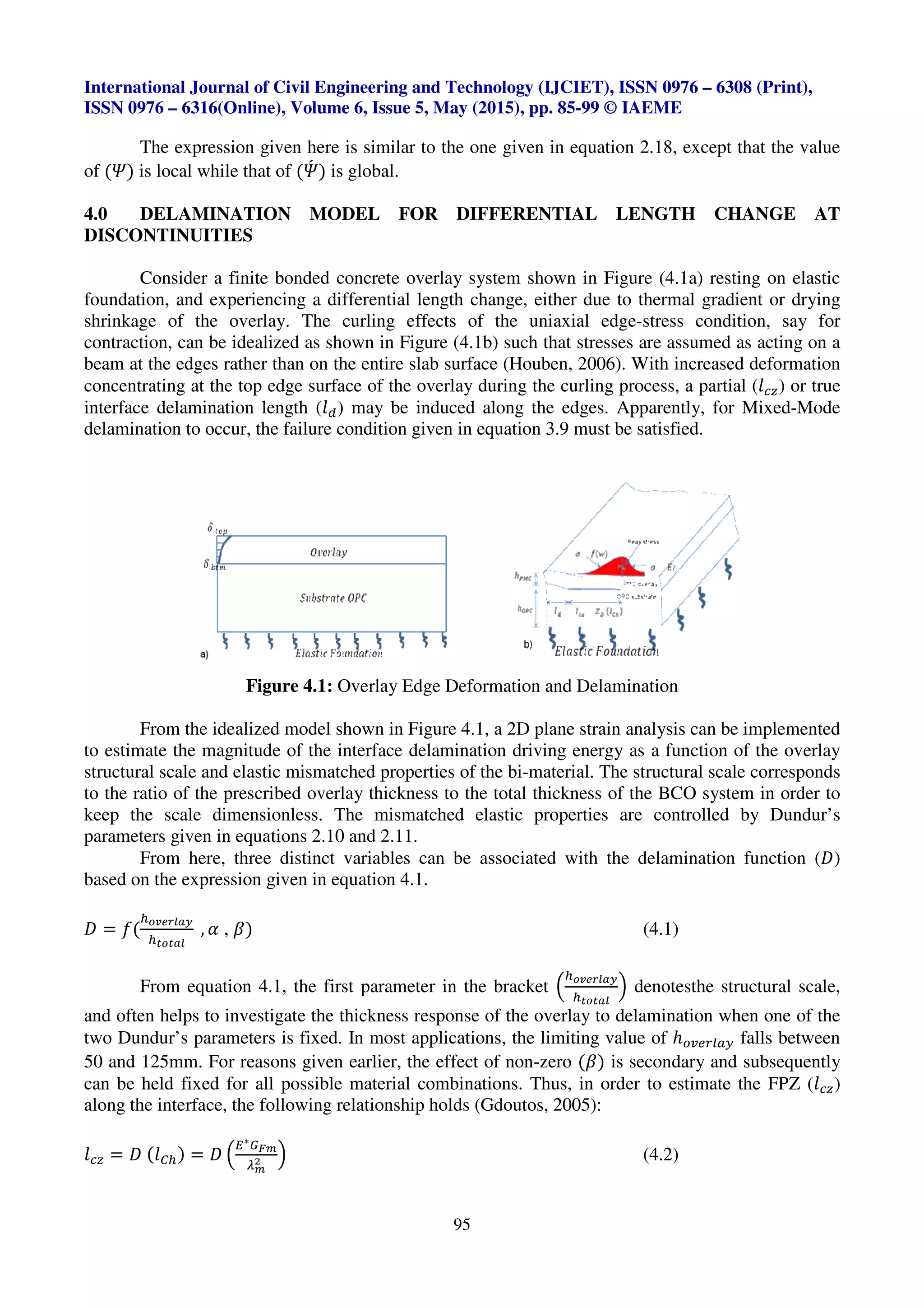
(a) (b)
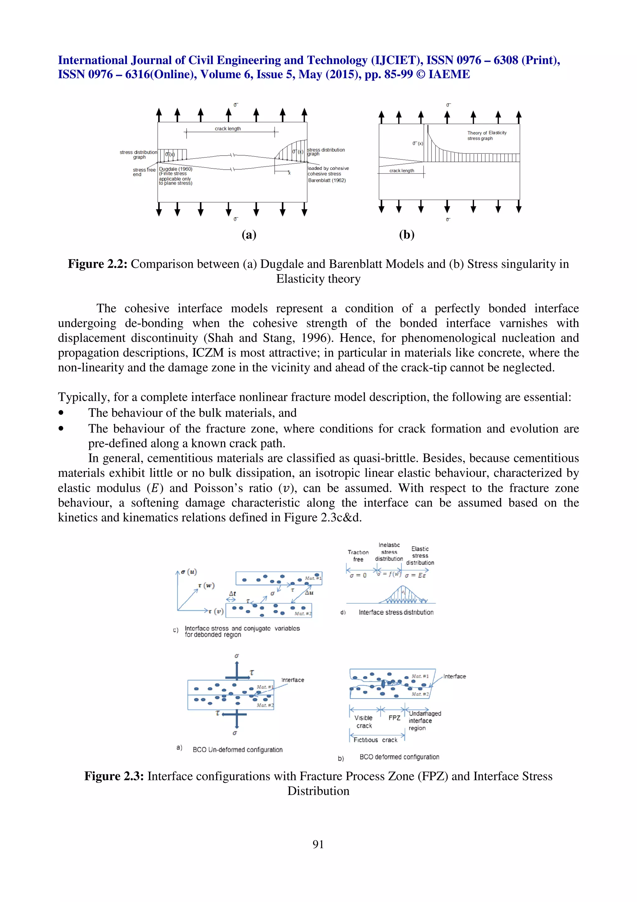
Figure 3.1: a) Definition of stress and conjugate variables, and b) Bilinear softening relation
As seen in Figure 3.1, the delamination process is defined by two slopes OA and AC. The
initial slope OA represents the linear elastic regime of the curve, while the second slope defines the
softening part of the curve in a linear function. De-bonding is assumed to initiate at peak contact
stress (‘•) at point A, and grows linearly as a function of de-bonding parameter (a). The value of (a)
evolves progressively from 0 to 1based on the conditions shown in equation 3.1till all the interface
stresses reduce to zero at critical crack point C (^’
i
).
a = “
0 b][ ^’ = ^”’
0 < a ≤ 1 b][ ^’ > ^”’
(3.1)
Where,
^’ = YdTV[VZW]X ]b Zℎd WXZd[bVpd dUdcdXZY ]Rd[ Zℎd dXZW[d U]VaWX_ ℎWYZ][˜.
^’ =
‘•
••
= p[WZWpVU YdTV[VZW]X b][ aVcV_d WXWZWVZW]X
‘• = p]ℎdYWRd YZ[dX_Zℎ
•• = WXWZWVU dUVYZWp p]XZVpZ YZWbbXdYY
Thus, for each mode of failure during loading, the fracture cohesive stress (™) can be related
to the opening or sliding displacement linearly by:
™ = “
‘ = •’^’(1 − a’) b][ `]ad š
› = •œ^œ(1 − aœ)b][ `]ad šš
(3.2)
Where, ‘ and › are the cohesive stresses in the normal and tangential directions respectively,
while•’ and •œ denote the corresponding contact stiffnesses. ^’and^œ represent the accompany
displacements after deformation,while a’ and aœ are the resulting de-bonding parameters in Mode I
and Mode II respectively.
However, for bonded dissimilar materials, Mixed-Mode delamination is common during
loading and failure process, thus, the criteria for damage initiation and final failure must account for
the concomitant effects of Mode I and Mode II. In that respect, both normal and tangential traction-
separation curves can be expanded in the (^’ VXa ^œ) - plane, as illustrated in Figure 3.2.From here,
it is clear that the normal and shear stresses depend not only on their corresponding displacement,
but on both the shear slip and normal opening as given in equation 3.3:
undeformed
deformed
0 (u)
1
7 (v)
u
v
7
7
1
0
n
A d = 0
n
K
0
1cohesivestress
0
B
(1-d ) K
un0
crack opening (u)
n
nd = 1n
C
slope=
slope=
un
c
un
1
0](https://image.slidesharecdn.com/interfacialdelaminationfailureinbondedconcreteoverlaysystemsareviewoftheoriesandmodellingmethods-150820093153-lva1-app6892/75/Interfacial-delamination-failure-in-bonded-concrete-overlay-systems-a-review-of-theories-and-modelling-methods-9-2048.jpg)
![International Journal of Civil Engineering and Technology (IJCIET), ISSN 0976 – 6308 (Print),
ISSN 0976 – 6316(Online), Volume 6, Issue 5, May (2015), pp. 85-99 © IAEME
96
Where, - is as defined in equation 4.1, U¡l is Hillerborg’s characteristic length defined by
u
O∗¶·¸
¹¸
/ v,P∗
= VRd[V_d dUVYZWp c]a^U^Y ]b Zℎd ºW − cVZd[WVU (YVcd VY d»^VZW]X 2.15),•z =
dbbdpZWRd Z[VpZW]X b][ cW¾da c]ad aVcV_d WXWZWVZW]X (YVcd VY d»^VZW]X 3.4),
eÁz = `W¾da − `]ad b[VpZ^[d dXd[_˜ = ey * eyy
ey = `]ad š b[VpZ^[d dXd[_˜ =
<
3
•z^z
i
p]Y3
w(4.3)
eyy = `]ad šš b[VpZ^[d dXd[_˜ =
<
3
•z^z
i
YWX3
w(4.4)
^z
i
= p[WZWpVU (dbbdpZWRd ) cW¾da c]ad aWY[UVpdcdXZ
If the Mixed-Mode delamination criterion is specified in terms of fracture energy, equations
4.5 and 4.6 hold:
u
¶§
¶§Â
v * u
¶§§
¶§§Â
v = 1 (4.5)
Since, eÁz = eyi * eyyi =
<
3
•z^z
i
= eyi Ip]Y3
w *
¶§Â
¶§§Â
YWX3
wJ
E<
(4.6)
Where, eÁz = b[VpZ^[d Z]^_ℎXdYY ][ p[WZWpVU b[VpZ^[d dXd_˜ b][ `W¾da − `]ad
eyi = Ã[VpZ^[d Z]^_ℎXdYY ][ p[WZWpVU b[VpZ^[d dXd[_˜ WX T^[d c]ad š
eyyi = Ã[VpZ^[d Z]^_ℎXdYY ][ p[WZWpVU b[VpZ^[d dXd[_˜ WX T^[d c]ad šš
Rearranging equation 4.2 and expressing the resulting energy release rate in terms of the
overlay structuralsize, equation 4.7obtains:
eÁ¸ = - (
l®¯°±²³´
lª®ª³²
, L , K)
¹¸
/ l®¯°±²³´
O∗
(4.7)
With respect to equation 3.9, the delamination failure definition given in equation 4.7 can
further be expressed as a function of the normalized interface toughness such that:
eQi = - (
l®¯°±²³´
lª®ª³²
, L , K) =
O∗
¶|Â(¢)
¹¸
/ l®¯°±²³´
(4.8)
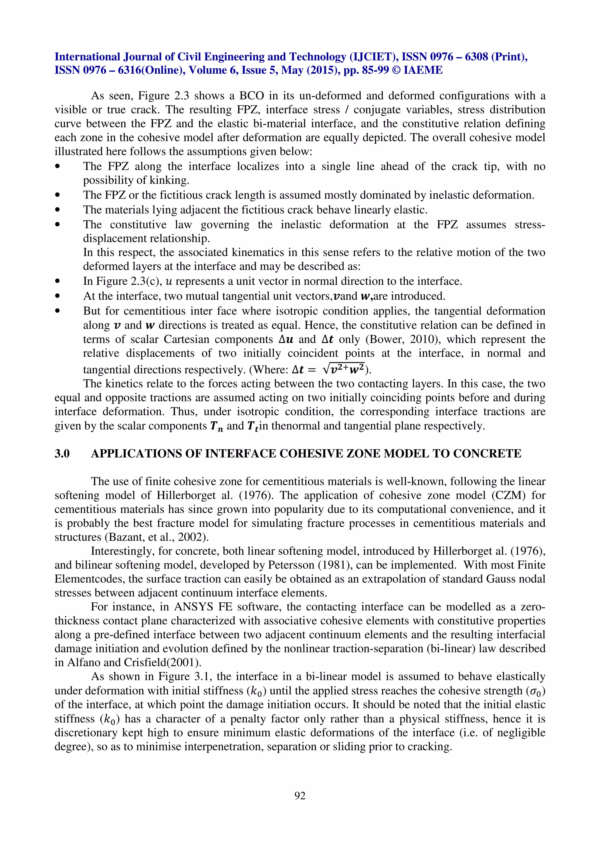
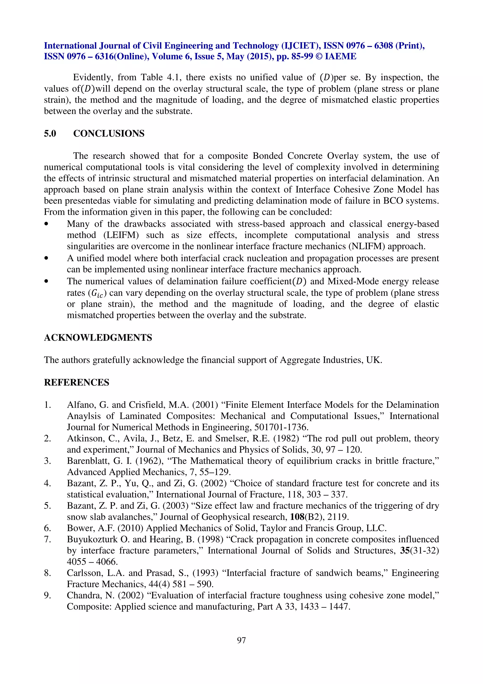
In this respect, the delamination failure coefficient(-) can be numerically estimated as a
function of the normalized structural scale for different values of (L). This approach relates to plane
strain problems and similar model has been presented elsewhere (Mei et al, 2010), though with a
structural scale adjustment. In the literature, several values of (-)based on plane stress problems also
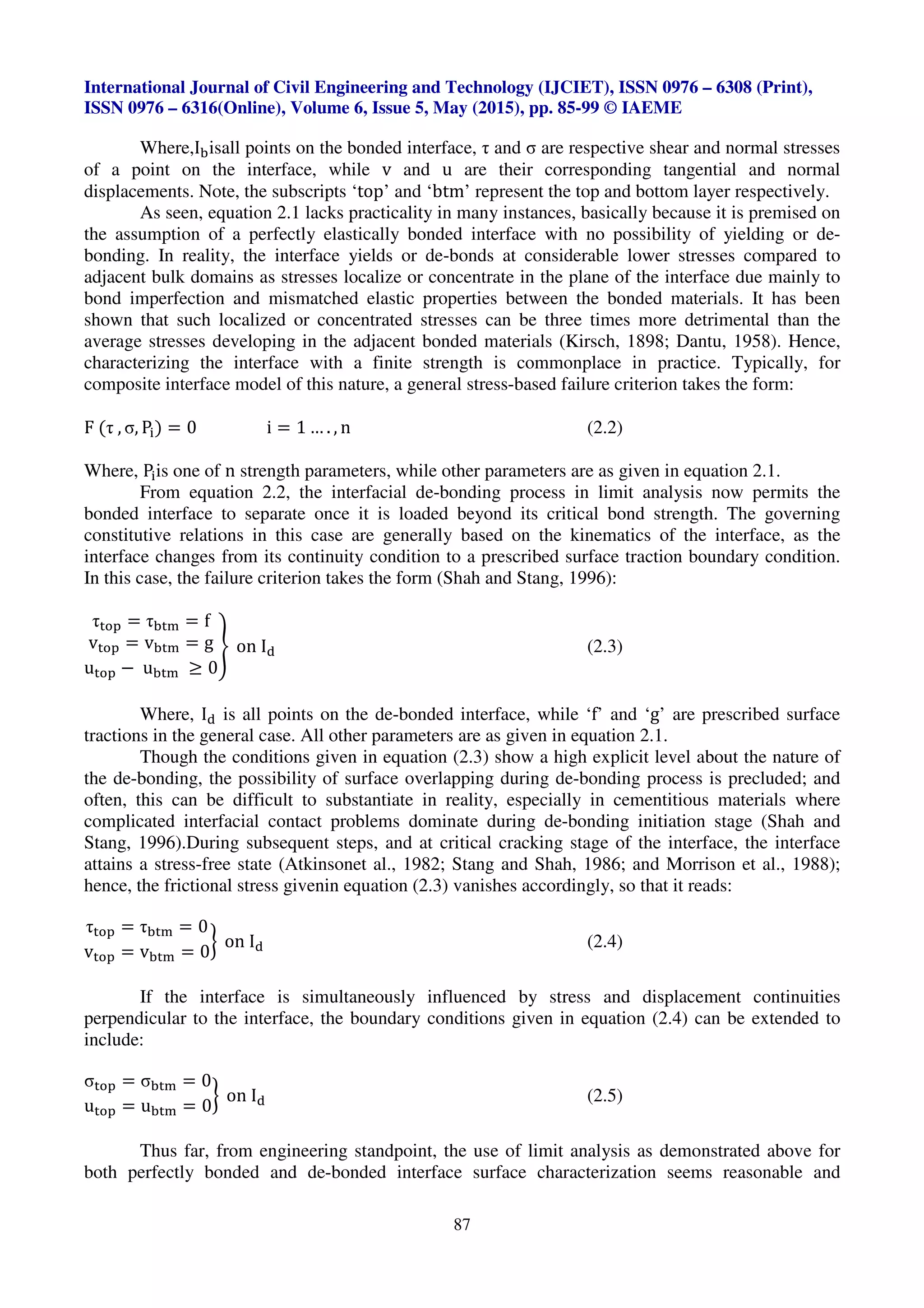
exist and they are reported in Turon, et. al.(2007). As illustrated in Table 4.1, such values range
between 0.21 and 1.0; though Hillerborg’s and Rice’s models where values of (-) approach or equal
to unityare mostcommon in practice.
Table 4.1: Cohesive zone length and equivalent delamination dimensionless parameter
`]adU Uiµ -
Hui 2 3r⁄ . P ep •iz
3
⁄ 0.21
Irwin 1 r⁄ . P ep •iz
3
⁄ 0.31
Dugdale, Barenblatt r 8⁄ . P ep •iz
3
⁄ 0.40
Rice, Falk 9r 32⁄ . P ep •iz
3
⁄ 0.88
Hillerborg P ep •iz
3
⁄ 1.00](https://image.slidesharecdn.com/interfacialdelaminationfailureinbondedconcreteoverlaysystemsareviewoftheoriesandmodellingmethods-150820093153-lva1-app6892/75/Interfacial-delamination-failure-in-bonded-concrete-overlay-systems-a-review-of-theories-and-modelling-methods-12-2048.jpg)
![International Journal of Civil Engineering and Technology (IJCIET), ISSN 0976 – 6308 (Print),
ISSN 0976 – 6316(Online), Volume 6, Issue 5, May (2015), pp. 85-99 © IAEME
98
10. Charalambides, P. G., Cao, H.C. Lund, J. Evans, A.G. “Development of a test method for
measuring the mixed mode fracture resistance of bimaterial interfaces,” Mechanics of
Materials, 8, 269 – 283 (1990).
11. Cornec, A., Scheider, I. and Schwalbe, K. (2003) “On the practical application of the cohesive
model,” Engineering Fracture Mechanics, 70(14), 1963-1987.
12. Dantu, P. (1958) “Study of the distribution of stresses in a two-component heterogeneous
medium. Symposium Non-Homogeneity in Elasticity and Plasticity,” Warsaw. Pergamon
Press, London, pp. 443 – 451.
13. Dugdale, D.S. (1960) “Yielding of steel sheets containing slits,” Journal of the Mechanics and
Physics of Solids, 8, 100- 104.
14. Dundurs, J. (1969) “Edge-Bonded Dissimilar Orthogonal Elastic Wedges Under Normal and
Shear Loading,” ASME Journal of Applied Mechanics, 36, 650 – 652.
15. Emmons, P.H. and Vaysburd, A.M. (1996) “System concept in design and construction of
durable concrete repairs,” Construction and Building Materials, 10 (1), 69 – 75.
16. Falk, M.L., Needleman, A., Rice J.R. (2001) “A critical evaluation of cohesive zone models of
dynamic fracture,” Journal de Physique IV, Proceedings, 543-550.
17. Gdoutos, E.E. (2005) Fracture Mechanics: An Introduction, 2nd edn. Springer.
18. Hillerborg, A., Modeer, M. and Petersson, P.E. (1976) “Analysis of crack formation and crack
growth in concrete by means of fracture mechanics and finite elements,” Cement and Concrete
Research, 6, 773 – 782.
19. Houben, L. J. M. (2003) “Structural design of Pavement – Part IV: Design of Concrete
Pavements, Lecture Notes CT4860,” Faculty of Civil Engineering and Geosciences, TU Delft;
Delft.
20. Hui, C.Y., Jagota, A., Bennison, S.J., Londono, J.D. (2003) “Crack blunting and the strength of
soft elastic solids,” Proceedings of the Royal Society of London A, 459, 1489-1516.
21. Irwin, G.R. (1960) “Plastic zone near a crack and fracture toughness. In Proceedings of the
Seventh Sagamore Ordnance Materials Conference,” vol. IV, 63-78, NewYork: Syracuse
University.
22. Karadelis, N.K. and Koutselas, K. (2003) “Sustainable ‘Green’ Overlays for Strengthening and
Rehabilitation of Concrete Pavements. In: Proceedings, 10th
International Conference,
Structural Faults + Repair,” London, UK, ISBN 0-947644-52-0, 94 (also on CD-ROM).
23. Kirsch, (1898) Die Theorie der Elastizität und die Bedürfnisse der Festigkeitslehre. Zeitschrift
des Vereines deutscher Ingenieure, 42, 797–807.
24. Mei, H., Pang, Y. and Huang, R. (2007) “Influence of Interfacial delamination on Channel
cracking of elastic thin-films,” Int. Journal of Fracture, 148, 331 – 342.
25. Mei, H., Gowrishankar, S., Liechti, K.M. and Huang, R. Initial and Propagation of interfacial
delamination integrated thin-film structureshttp://www.utexas.academia.edu
/ShravanGowrishankar [12November 2010].
26. Morgan, D.R. (1996) “Compatibility of concrete repair materials and systems,” Construction
and Building Material, 10, No.1, 57-67.
27. Mormonier, M.F., Desarmot, G., Barbier, B. and Letalenet, J.M. (1988) “A study of the pull-
out test by a finite element method (in French),” Journal of Theoretical and Applied
Mechanics, 7, 741 – 765.
28. Morrison, J.K., Shah, S.P. and Jena, Y.S. (1988) “Analysis of fibre debonding and pullout in
composites,” ASCE Journal of Engineering Mechanics, 114(2), 277 – 294.
29. Olubanwo A.O. (2013) “Optimum design for Sustainable ‘Green’ Bonded Concrete Overlays:
Failure due to shear and delamination.”PhD Thesis, Department of Civil Engineering,
Architecture, and Building Coventry University, United Kingdom.](https://image.slidesharecdn.com/interfacialdelaminationfailureinbondedconcreteoverlaysystemsareviewoftheoriesandmodellingmethods-150820093153-lva1-app6892/75/Interfacial-delamination-failure-in-bonded-concrete-overlay-systems-a-review-of-theories-and-modelling-methods-14-2048.jpg)

This document reviews theories and modeling methods for describing delamination failure at the interface between two bonded cementitious materials. It discusses traditional stress-based and energy-based failure criteria approaches. It presents the interface cohesive zone model (ICZM) as a viable approach for describing and predicting delamination in bonded concrete overlay systems. The ICZM treats delamination as a progressive failure involving both crack initiation and propagation. It considers distinct analytical cases involving material and structural property variables. The concluding model shows that numerical values of delamination coefficients and energy release rates vary depending on overlay scale, problem type, and material property mismatches.


