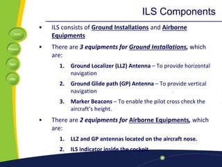
3. Home
Previous
Next
Help
What Is ILS?
• ILS is stand for Instrument Landing System.
• It has been existence for over 60 years.
• But today, it is still the most accurate approach
and landing aid that is used by the airliners.
• Why need ILS?
5. Home
Previous
Next
Help
The Uses of ILS
• To guide the pilot during the approach and landing.
– It is very helpful when visibility is limited and the
pilot cannot see the airport and runway.
• To provide an aircraft with a precision final
approach.
• To help the aircraft to a runway touchdown point.
• To provide an aircraft guidance to the runway both
in the horizontal and vertical planes.
• To increase safety and situational awareness.
10. Home
Previous
Next
Help
Types of Runway Approach
1.Non-Instrument Runway (NI)
– A runway intended for the operation of aircraft using visual
approach procedure
2. Instrument Runway
– A runway intended for the operation of aircraft using instrument
approach procedures
a) Non-Precision Runway (NP)
• An instrument runway served by visual aids and a non-visual aid
providing at least lateral guidance adequate for a straight-in
approach
b) Precision Runway (P)
• Allow operations with a decision height and visibility
corresponding to Category 1, or II, or III
11. Home
Previous
Next
Help
Precision Runway (P) Categories
• Runway Threshold: Beginning of runway for
landing.
• Touchdown zone: The first point for the aircraft
shoul touch the runway during landing.
• Aiming point: serves as a visual aiming point for
a landing aircraft.
12. Home
Previous
Next
Help
ILS Components
• ILS consists of Ground Installations and Airborne
Equipments
• There are 3 equipments for Ground Installations, which
are:
1. Ground Localizer (LLZ) Antenna – To provide horizontal
navigation
2. Ground Glide path (GP) Antenna – To provide vertical
navigation
3. Marker Beacons – To enable the pilot cross check the
aircraft’s height.
• There are 2 equipments for Airborne Equipments, which
are:
1. LLZ and GP antennas located on the aircraft nose.
2. ILS indicator inside the cockpit
15. Home
Previous
Next
Help
How ILS works?
• Ground localizer antenna transmit VHF signal in direction
opposite of runway to horizontally guide aircraft to the runway
centre line.
• Ground Glide Path antenna transmit UHF signal in vertical
direction to vertically guide aircraft to the touchdown point.
• Localizer and Glide Path antenna located at aircraft nose
receives both signals and sends it to ILS indicator in the cockpit.
• These signals activate the vertical and horizontal needles inside
the ILS indicator to tell the pilot either go left/right or go
up/down.
• By keeping both needles centered, the pilot can guide his
aircraft down to end of landing runway aligned with the
runway center line and aiming the touch down.
17. Home
Previous
Next
Help
Question Banks
• What is Localizer and how does it works?
• What is Glide Slope and how does it works?
• An Airport with an ILS is often rated as Cat 1 or
Cat II or Cat III. Explain the definition of these.
• Explain Outer Marker, Middle Marker and Inner
Marker of ILS system.
19. Home
Previous
Next
Help
How Localizer Works
• Localizer transmit two signals which overlap at the
centre.
• The left side has a 90 Hz modulation and the right has a
150 Hz modulation.
• The overlap area provides the on-track signal.
• For example, if an aircraft approaching the runway
centre line from the right, it will receive more of the
150 Hz modulation than 90Hz modulation.
• Difference in Depth of Modulation will energizes the
vertical needle of ILS indicator.
• Thus, aircraft will be given the direction to GO LEFT.
22. Home
Previous
Next
Help
Glide Path Antenna Array
• Glide Path is the vertical antenna located on
one side of the runway about 300 m to the end
of runway.
• Glide Path operates in UHF band between
329.15 and 335 MHz
23. Home
Previous
Next
Help
How Glide Path Works
• Glide path produces two signals in the vertical plane.
• The upper has a 90 Hz modulation and the bottom has
a 150 Hz modulation.
• For example, if an aircraft approaching the runway too
high, it will receive more of the 90 Hz modulation than
150Hz modulation.
• Difference in Depth of Modulation will energizes the
horizontal needle of ILS indicator.
• Thus, aircraft will be given the direction to GO DOWN.
27. Home
Previous
Next
Help
Marker Beacons
• Marker beacons operating at a carrier
frequency of 75 MHz are provided.
• When the transmission from a marker beacon is
received it activates an indicator on the pilot's
instrument panel.
• The correct height the aircraft should be at
when the signal is received in an aircraft.
28. Home
Previous
Next
Help
Marker Beacons
Outer marker
• The outer marker should be located about 7.2 km from the
threshold.
• The modulation is repeated Morse-style dashes of a 400 Hz
tone.
• The cockpit indicator is a blue lamp that flashes accordingly
with the received audio code.
• The purpose of this beacon is to provide height, distance and
equipment functioning checks to aircraft on intermediate
and final approach.
29. Home
Previous
Next
Help
Marker Beacons
Middle marker
• The middle marker should be located so as to indicate,
in low visibility conditions.
• Ideally at a distance of 1050m from the threshold.
• The cockpit indicator is an amber lamp that flashes in
accordingly with the received audio code.
30. Home
Previous
Next
Help
Marker Beacons
Inner marker
• The inner marker, shall be located so as to
indicate in low visibility conditions.
• This is typically the position of an aircraft on the
ILS as it reaches Category II minima.
• The cockpit indicator is a white lamp that
flashes in accordingly with the received audio
code.
31. Home
Previous
Next
Help
ILS Categories
• There are three categories of ILS the operation.
• Category I - A precision instrument approach and landing with a
decision height not lower than 60 m (200 ft) above touchdown
zone elevation and with either a visibility not less than 800 m or a
runway visual range not less than 550 m.
• An aircraft equipped with an Enhanced Flight Vision System may,
under certain circumstances, continue an approach to CAT II
minimums.
• Category II - Category II operation: A precision instrument
approach and landing with a decision height lower than 60 m (200
ft) above touchdown zone elevation but not lower than 30 m (100
ft), and a runway visual range not less than 350 m.
32. Home
Previous
Next
Help
ILS Categories
• Category III is further subdivided
– Category III A - A precision instrument approach and landing with:
• a) a decision height lower than 30 m (100 ft) above
touchdown zone elevation, or no decision height; and
• b) a runway visual range not less than 200 m.
– Category III B - A precision instrument approach and landing with:
• a) a decision height lower than 15 m (50 ft) above touchdown
zone elevation, or no decision height; and
• b) a runway visual range less than 200 m but not less than 50
m.
– Category III C - A precision instrument approach and landing with
no decision height and no runway visual range limitations. A
Category III C system is capable of using an aircraft's autopilot to
land the aircraft and can also provide guidance along the runway.
34. Home
Previous
Next
Help
Disadvantages of ILS
• Interference due to large reflecting objects,
other vehicles or moving objects.
• This interference can reduce the strength of the
directional signals.