Downloaded 28 times


![Integrated Master Plan / Integrated Master Schedule Step-by-Step
Glen B. Alleman, Copyright © 2021 11 | P a g e
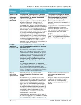
Understand the Product
Defining the program framework starts with understanding the product, the customer and the processes that will
be used to deliver the product. By first identifying all the discrete work scope and categorizing them into – who,
what, when, where, why and how categories, the pro duct structure can emerge.
Develop Product Structure
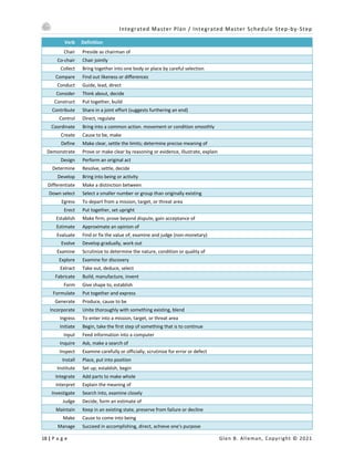
The product structure starts with the Work Breakdown Structure (WBS).
A Program WBS “… shall be established that provides a framework for program and technical planning, cost
estimating, resource allocations, performance measurements, and status reporting.” DODD 5000.2R
The WBS establishes the primary portioning of the product and work needed to produce the product. The WBS
outlines the products and services to be provided by the program in a “structured” manner where each product
and or service is traceable to its parent product and or service. The result is a “Product Tree” that decomposes the
program structure to a level where risks are made visible. This is usually Level 3 in the WBS.
The WBS defines the logical structure of the program. Summary points for assessing technical and programmatic
risk and the physical progress of the work activities. It is critical to not let the WBS be a representation of the
organizational structure of the program. If this is done the ability to measure physical progress through the
production of products or services is lost.
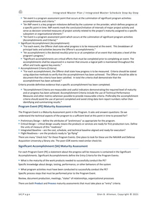
Form Integrated Product Teams (IPTs) and Align Their Work Efforts
“We trained hard, but it seemed that every time we were beginning to form up into teams, we would be
reorganized. I was to learn later in life that we tend to meet any new situation by reorganizing; and a wonderful
method it can be for creating the illusion of progress while producing confusion, inefficiency and demoralization.”
– Petronius Arbiter (210 B.C.)
Align the Work Between the IPTs
§ Our team structure needs to reflect the most cost-efficient way of organizing the work
§ Our team structure needs to be sized according to the work required
§ Our teams must not be too big or too small to be functional
§ Our team structure needs to account for vertical (product) and horizontal (process, system) integration
§ Our team structure must not unnecessarily complicate integration or production
§ Our team structure must have clear scope borders — know where one team’s scope ends, and another team’s
scope begins
Integrate across the products to deliver the system-level configurations and data to the customer:
§ Integrate, analyze, assemble, and test configurations made up of modules developed and delivered by IPTs
§ Integrate program / system level data and CDRL items
§ Electronic Information System (EIS) or Integrated Data Environment (IDE) [both terms used in RFPs]
Own and audit the common program infrastructure resources employed by multiple teams:
§ Processes
§ Tools
§ Databases
§ Facilities
§ Equipment](https://image.slidesharecdn.com/imp-210511164151/85/IMP-IMS-Step-by-Step-19-320.jpg)


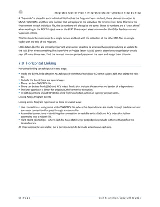
![Integrated Master Plan / Integrated Master Schedule Step-by-Step
42 | P a g e Glen B. Alleman, Copyright © 2021
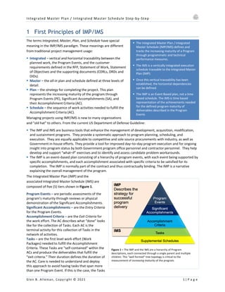
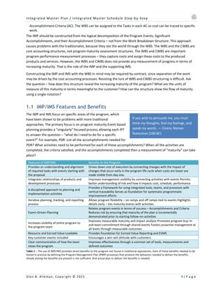
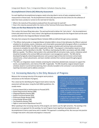
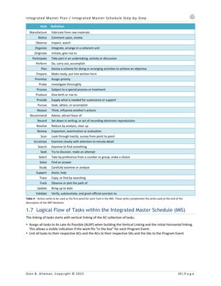
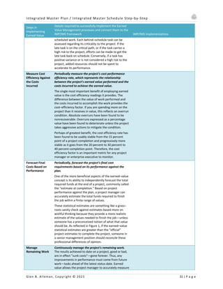
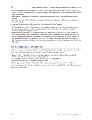
§ The IMS is an integrated, networked,
multi-layered schedule of program tasks
to complete the work effort captured in
the IMP.
§ The IMS should include all IMP events
and accomplishments and support each
accomplishment closure criteria.
§ The IMS is a performance forecasting
tool as well as a Master Schedule and
Risk identification tool.
§ The IMS connects the IMP, which shows
the increasing maturity of the program
with the activities needed to produce
the evidence that maturity is increasing.
§ Through PDR the majority of the work is
building the deliverables from the
CDRLs
§ Building the initial plan of the “planned
outcomes” from the CDRLs – as their
maturity is defined – is the starting
point
§ Each CDRL should be assigned to a
single AC and be connected to a single
PE for the defined maturity level.
§ The Capabilities Solution
§ Past Performance Relative to this program and any Key Supplier’s data that described past performance
§ Facilities and Equipment needed to successfully deliver the product including Internal and Key Suppliers
§ Any Key Personnel IPT Lead Names and Resumes and the Key Supplier’s Lead Names and Resumes
§ The Cost Solution
§ Supplier Costs
§ Material Costs
§ Capital Expenditures
§ Engineering and other Labor Costs
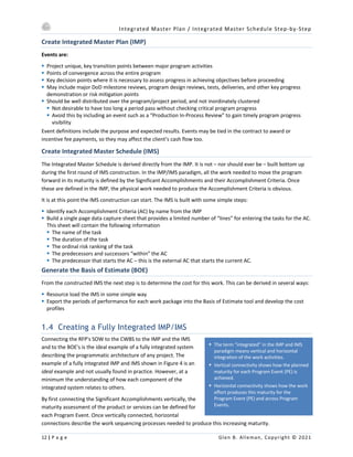
3.1 Building a CDRLs plan
The CDRLs deliverables plan is usually a huge mess. CDRLs are
assigned delivery dates before, during, and after Program Events.
Different version or revisions of the CDRLs are due at different
points in the program. Keeping track of all these moving parts,
starts with the understanding of what the CDRLs actually say in the
body of their text about delivery. Several approaches can be taken:
§ Build a database that keeps track of all the dependencies
§ Build a schedule that describes the delivery of the CDRLs
This may appear over kill but it is not. The CDRL compliance is a
critical factor through PDR. Also the CDRL’s are the actual
deliverables through PDR, since up to that point the program
rarely produces are hardware or software products – just designs, models, trade studies and other paper based
assessments.
Inside the CDRLs are references to other dependencies like dates, review cycles and the like.
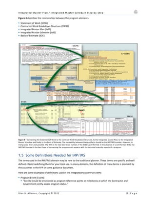
3.2 The Integrated Master Schedule (IMS)
The IMS is a living document that is continuously updated to
reflect the progress of the program or project. The IMS should:
[Guide 05]
§ Maintain consistency with the IMP
§ Illustrate the interrelationships among events, accomplishments,
criteria, and tasks
§ Indicate the start and completion dates and duration for each
event, accomplishment, criterion and task
§ Provide for critical path analysis
§ Provide the ability to sort schedules multiple ways (e.g., by
event, by Integrated Product Team (IPT), or by WBS)
§ Provide schedule updates on a regular basis, indicating
completed actions, schedule slips, and rescheduled actions
§ Provide the capability for the Government, contractor, or
support contractors to perform “what if” schedule exercises
without modifying the master program schedule
§ Maintain consistency with the work package definitions and the Earned Value Management System (EVMS)
§ Be traceable between the WBS items supported by each IMS task
§ Be vertically and horizontally traceable to the cost and schedule reporting instrument (e.g., Cost Performance
Report (CPR))](https://image.slidesharecdn.com/imp-210511164151/85/IMP-IMS-Step-by-Step-50-320.jpg)

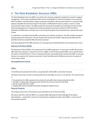


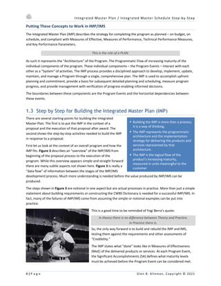
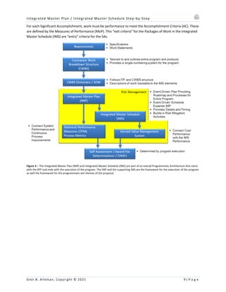
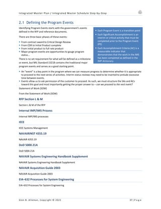
The document outlines the process for developing an Integrated Master Plan (IMP) and Integrated Master Schedule (IMS) as essential components of project management in defense acquisition. It emphasizes the shift from traditional project planning metrics to a focus on measurable progress through defined accomplishment criteria, significant accomplishments, and event-driven acquisition strategies. Additionally, it provides step-by-step guidance on creating and integrating these plans within a systems engineering context to enhance program execution and manage risk effectively.