Downloaded 11 times
![International Journal of Computer Applications Technology and Research
Volume 4– Issue 2, 149 - 152, 2015, ISSN:- 2319–8656
www.ijcat.com 149
Design and Analysis of Robotic Rover with Gripper Arm
using Embedded C
Harmeet Singh, Sangeeta
Department of Computer Science
Punjab College of Technical Education (PCTE)
Baddowal, Punjab, India
Harpreet Kaur
Department of Electronics and Communication
Engineering
Sant Longowal Institute of Engineering and Technology
(SLIET) Longowal, Punjab, India
Abstract: This paper confers the development and working of robotic rover performing various autonomous tasks to identify, pick and
drop an object at an appropriate position using microcontroller 8051 in conjunction with embedded C programming. The system
employs infrared proximity sensors, DC geared motors, microcontroller board, etc. Robotic rover technology offers many applications
in space explorations, military operations, etc. The motive of this research work is to design a wireless robotic rover being autonomous
controlled that is capable of completing tasks with proliferated accuracy in smooth terrain.
Keywords: Robotic Rover; Embedded C; Microcontroller; Programming; Sensor
1. INTRODUCTION
Robotics technology is emanating at an expeditious pace,
contributing new possibilities for automating tasks in many
demanding applications, peculiarly in space explorations,
military operations, underwater missions, etc. Especially, in
space exploration, robotic devices are known as planetary
rovers or simply rovers who aim at administering physical
analysis of planetary terrains and astronomical bodies. The
supervision of data about air pressure, climate, temperature,
and other atmospheric aspects can be done by this advanced
technology [1,5,9]. It is a space exploration vehicle designed
to move across the surface of a planet or other heavenly body.
Primarily, rovers can be self-governing or can be remotely
controlled from the ground stations called as Remote
Collaboration Center having very definite scientific
objectives. Some rovers have been devised in the
transportation of members of a human spaceflight crew;
others have been partially or fully autonomous robots. Rovers
or Unmanned Ground Vehicles (UGV) usually arrive at the
planetary surface on a lander-style spacecraft [2,7-8]. The
investigation of territories at the microscopic level,
investigating the biological aspects of planetary surfaces,
analyzing the composition of minerals, rocks, and soils,
searching for liquid water in minerals, and measuring the
ambient temperature, air pressure, and amount of dust in the
landing site are some of its imperative appositeness [3].
Therefore, rovers are eminently computing systems that use
complicated embedded software and algorithms to handle
computational and processing functionalities.
Figure.1 Schematic of Curiosity Rover on Mars
An autonomous robot has the competence to:
Collect information about the environment, such as
building maps of building interiors.
Detect objects of interest such as people and
vehicles.
Travel between targets without human navigation
and intervention.
Disarm, or remove explosives.
Repair itself without outside assistance.
The ongoing Mars exploration focuses around surface
exploration using satellites and small, autonomous land-
exploration rovers which are used in predilection to manned
missions as the cost is substantially lower and the rovers are
more suited to the harsh planetary environment. Manned
missions are still regarded as the „holy grail‟ of topographical
exploration; a current rover mission is aiming to scrutinize
Mars with a pair of rovers, providing scope for coordination
which was hitherto only possible with human exploration
[1,3-4,6]. This paper is intended to study and discuss the
design and development of robotic rover, its fully autonomous
functionalities with various other capabilities.
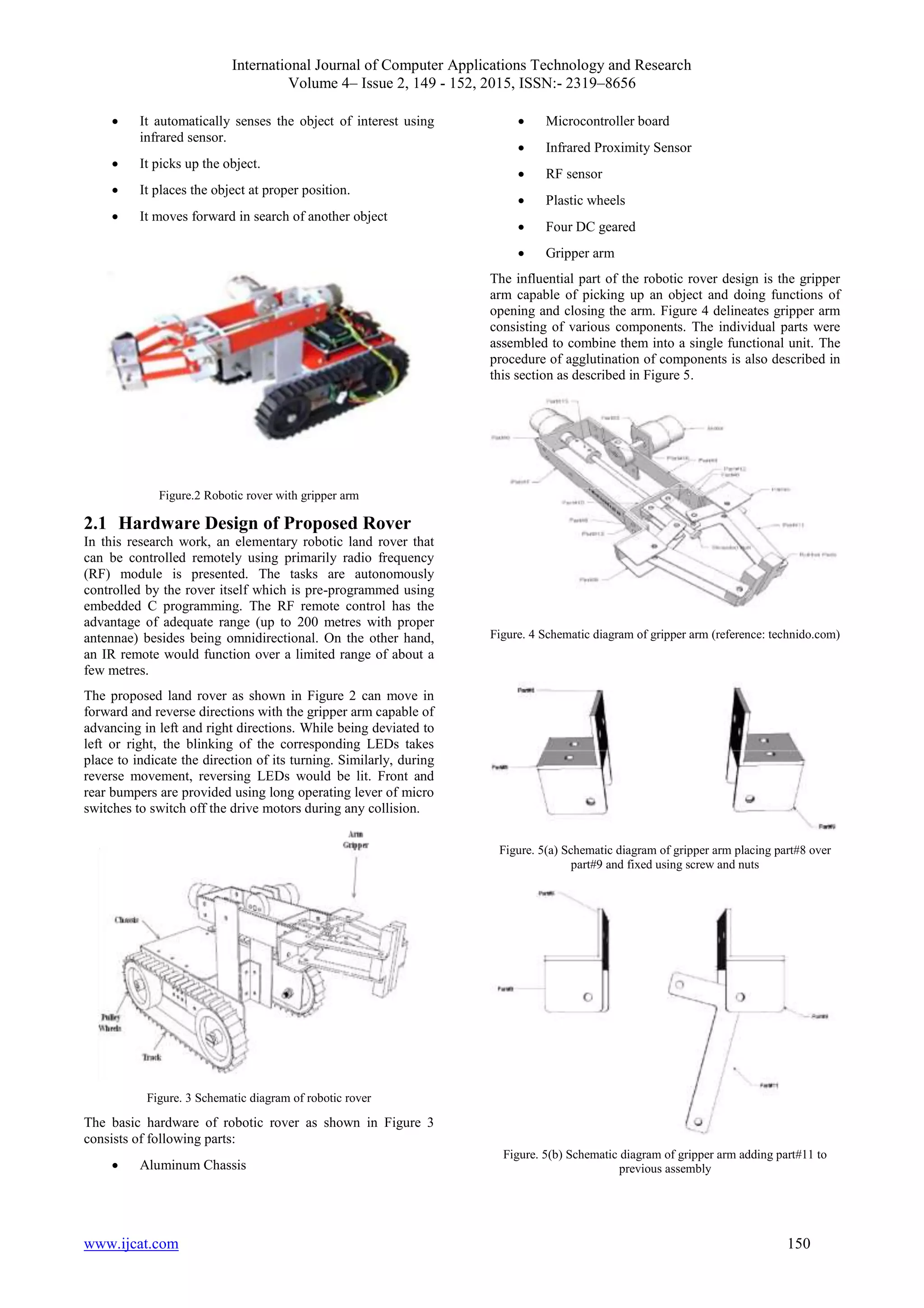
2. ROBOTIC ROVER DESIGN
The structural part involves use of frames, beams, linkages,
axles, etc. The mechanical parts/accessories comprise various
types of gears (spurs, crowns, bevels, worms and differential
gear systems), pulleys and belts, drive systems (differentials,
castors, wheels and steering), etc. Pneumatics plays a vital
role in generating specific pushing and pulling movements
such as those simulating arms or leg movements. Pneumatic
grippers are also used with advantage in robotics because of
their simplicity and cost-effectiveness. The electrical items
include DC and stepper motors, actuators, electrical grips,
clutches and their control. The electronics part involves
remote control, sensors (touch sensor, light sensor, collision
sensor, etc), their interface circuitry and a microcontroller for
overall control function.
The main objectives of the robotic rover project are given
below:](https://image.slidesharecdn.com/ijcatr04021012-150312085835-conversion-gate01/75/Design-and-Analysis-of-Robotic-Rover-with-Gripper-Arm-using-Embedded-C-1-2048.jpg)
![International Journal of Computer Applications Technology and Research
Volume 4– Issue 2, 149 - 152, 2015, ISSN:- 2319–8656
www.ijcat.com 152
debugger are assimilated in a single application that provides
a seamless embedded project development environment. Flash
magic software was used as program burner which is a PC
tool for programming flash based microcontrollers from NXP
using a serial or Ethernet protocol while in the target
hardware.
Figure. 6 Flow chart depicting working of proposed robotic rover
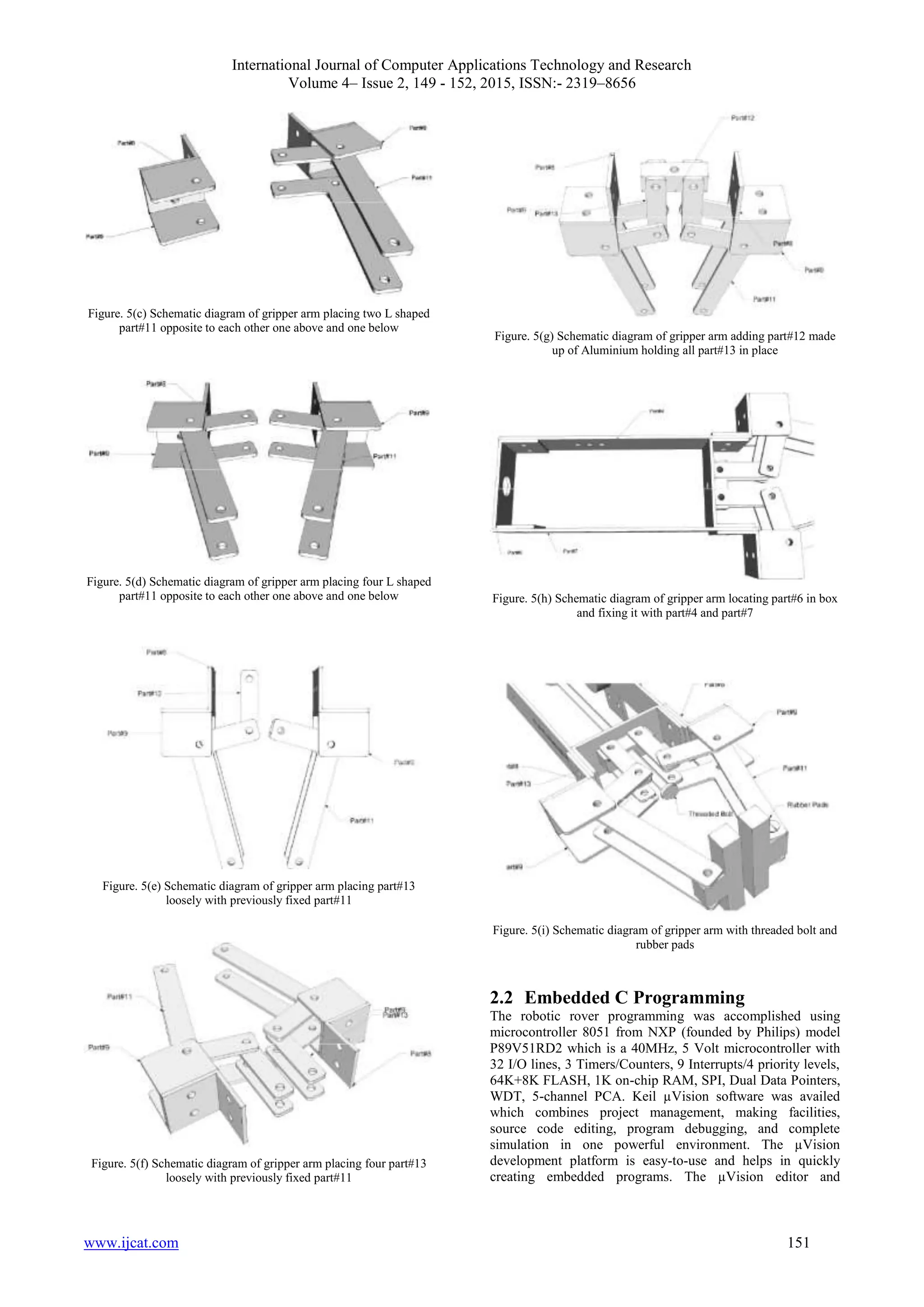
2.3 Working of Robotic Rover
Figure 6 illustrates the dynamics of robotic rover with gripper
arm facility. This robot firstly moves in forward direction in
search of an object. Here, the IR sensor plays a crucial role.
The object is detected when the distance between the IR
sensor and the object of interest is approximately 12 cm (the
range can be further increased). If the object is encountered,
its arm grip is released and moved in downward direction.
Then the arm grip grasps again and picks up the object. It is
placed in right direction where the arm gripper releases the
object. It maneuvers in upward direction and robotic rover
proceeds in forward direction. The programming of the whole
operation is done in embedded C language using Keil µVision
3 tool from ARM Ltd.
3. RESULTS
Table 1. Table captions should be placed above the table
Steps Operations
Time taken to
complete (sec)
Step 1 Release of Gripper arm 15
Step 2 Down 4
Step 3 Grip (object) 11
Step 4 Up 5
Step 5 Right/left 5
Step 6 Down 3
Step 7 Release 12
Step 8 Up 5
Step 9 Grip (empty) 15
Step 10 Left/right 5
The robotic rover functionality comprises of some basic steps
which were made fully autonomous using embedded C
programming. The RF module was used to switch on/off the
rover. Firstly, the release of empty gripper arm has taken a
considerable time of 15 sec followed by down movement of 4
sec. Due to presence of gravity of earth, down movement took
minimum time among all other operations. Thenceforth, the
object was grasped by the gripper arm covering a total of 11
sec. The gripping and releasing operations done by gripper
arm clutched substantial seconds as shown in table 1.
Hereafter, the up movement of gripper arm took place with 5
seconds and positioning the object left/right. The object was
then placed by a down release of 3 seconds since both the law
of gravity and the weight of object exerted a downward force.
Placing the object at proper place was the most momentous
task. It took a second highest time of 12 sec with release
operation of the arm. Consequently, the arm was moved in
upward direction with gripping of the arm. These operations
were continued until and unless an object of interest was
discovered.
4. CONCLUSIONS
This paper has bestowed an overview of the proposed robotic
rover which can be used for sensing and navigation. It can be
made fully autonomous with in-built camera, high
performance controller, ultrasound sensors for future work.
These enhancements will foster its capability for long range
navigation. Being a latest technology in India, it would be
benefaction for our space and defense applications.
5. ACKNOWLEDGMENTS
The authors are indebted to Kits„n‟Spares, New Delhi and
Technido Indore, India for providing Robotic Rover parts and
technical help for making this work successful.
6. REFERENCES
[1] Zerigui A., WU X., Deng Z., “A Survey of Rover
Control Systems”, International Journal of Computer
Sciences and Engineering Systems, Vol. 1, No. 4, pp.
105-109, 2007.
[2] Siegwart R., Nourbakhsh I., Scaramuzza D.,
Introduction to Autonomous Mobile Robots, 2nd edition,
The MIT Press, 2011.
[3] Young A., Lunar and Planetary Rovers: The Wheels of
Apollo and the Quest for Mars, Springer, 2006.
[4] Svitak, Amy, Cost of NASA's Next Mars Rover Hits
Nearly $2.5 Billion, http://www.space.com/10762-nasa-
mars-rover-overbudget.html, retrieved 2011-02-03.
[5] Wesley T. Huntress JR., Mikhail Ya Marov, Soviet
Robots in the Solar System: Mission Technologies and
Discoveries, Springer, 2011.
[6] E. Colon, H. Sahli, and Y. Baudoin, ―CoRoBa, a multi
mobile robot control and simulation framework,
International Journal of Advanced Robotic Systems, Vol.
3, No. 1, pp. 073-078, 2006.
[7] iRobot, Mobility Integration Software User's Guide,
2002.
[8] Cherry S., Robots, IEEE Spectrum, 2007.
[9] B. Gerkey, R. Vaughan, K. Sty, A. Howard, G.
Sukhatme, and M. Mataric, ―Most valuable player: A
robot device server for distributed control‖, In
Proceedings of the IEEE/RSJ International Conference
on Intelligent Robots and Systems (IROS), 2001.](https://image.slidesharecdn.com/ijcatr04021012-150312085835-conversion-gate01/75/Design-and-Analysis-of-Robotic-Rover-with-Gripper-Arm-using-Embedded-C-4-2048.jpg)

This document presents the design and analysis of a robotic rover equipped with a gripper arm, capable of autonomously identifying, picking, and placing objects using embedded C programming on a microcontroller 8051. The rover employs various sensors, motors, and a radio frequency module for control, making it suitable for operations in space exploration and military applications. The paper discusses hardware design, functionality, and the programming processes that enable the rover's autonomous behavior.