Download to read offline
![International Research Journal of Engineering and Technology (IRJET) e-ISSN: 2395-0056
Volume: 05 Issue: 04 | Apr-2018 www.irjet.net p-ISSN: 2395-0072
© 2018, IRJET | Impact Factor value: 6.171 | ISO 9001:2008 Certified Journal | Page 1345
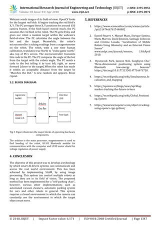
Simultaneous Localization and Mapping for Automatic Chair Re-
arrangement System
Prof. Swapna Borde1, Reuben A. Fernandes2, Manoj S. Goregaonkar3, Kapilesh D. Gujarathi4
1,2,3,4 Department of Computer Engineering, VIDYAVARDHINI’S COLLEGE OF ENGINEERING AND TECHNOLOGY
K.T. MARG, VASAI ROAD (W), DIST-PALGHAR, PIN: 401202.
-----------------------------------------------------------------***--------------------------------------------------------------
Abstract- Mapping is the computational problem of
constructing or updating a map of an unknown
environment while simultaneously keeping track of an
agent's location within it. Localization means the process
of determining the location of an agent with respect to
some know reference .These techniques are cumulatively
termed as SLAM (simultaneous localization and mapping),
and can be used for the automation of any system. SLAM is
a topic of ongoing research in computer technology. There
are many know techniques to implement SLAM. Our goal is
to demonstrate a SLAM technique by implementing it in an
“Automatic Chair Re-arrangement system”. This system
automates the movement of a chair so that it can move
back to its original location post being displaced.[4]
Keywords- Mapping, Localization, Automation, SLAM,
Chair.
1. INTRODUCTION
THE solution to the simultaneous localization and map
building (SLAM) problem is, in many respects, a “Holy
Grail” of the autonomous vehicle research community.
The ability to place an autonomous vehicle at an
unknown location in an unknown environment and then
have it build a map, using only relative observations of
the environment, and then to use this map
simultaneously to navigate would indeed make such a
robot “autonomous”. Thus the main advantage of SLAM
is that it eliminates the need for artificial infrastructures
or a priori topological knowledge of the environment. A
solution to the SLAM problem would be of inestimable
value in a range of applications where absolute position
or precise map information is unobtainable, including,
amongst others, autonomous planetary exploration,
subsea autonomous vehicles, autonomous air-borne
vehicles The general SLAM problem has been the subject
of substantial research since the inception of a robotics
research community and indeed before this in areas such
as manned vehicle navigation systems and geophysical
surveying. A number of approaches have been proposed
to address both the SLAM problem and also more
simplified navigation problems.
2. EXISTING METHODOLOGIES
2.1 Dead Reckoning:
Dead reckoning, a method of navigation that uses on-
board sensors to measure speed and heading based on
the last known position to estimate its current position,
becomes important. On-board sensors, gyroscopes and a
compass, provide vehicle attitude and orientation
information. Speed is either measured in real time or is
determined empirically through testing. When
accelerometers are available on-board, a more advanced
form of dead reckoning known as inertial navigation is
possible. Inertial navigation integrates accelerations and
rotation rates of a body in time to determine attitude and
heading. [1]
Drawbacks:
Errors in dead reckoning result from many sources,
including inaccurate knowledge of the vehicle’s starting
position, a misalignment of the heading sensor, and the
time-varying effects of the sensors. Any errors present in
the initial conditions will be propagated throughout the
vehicle run. Similarly, a misaligned compass causes a
constant offset in all measurements and translates over
time into an estimated heading trajectory that deviates
from the actual vehicle trajectory. Finally, the constant
drift in gyroscopes becomes significant with time.
2.2. Odometry:
Odometry is the use of data from motion sensors to
estimate change in position over time. It is used
in robotics by some legged or wheeled robots to estimate
their position relative to a starting location. Each motor
has a rotary encoder, and so one can determine if either
wheel has travelled one "unit" forward or reverse along
the floor. This unit is the ratio of the circumference of the
wheel to the resolution of the encoder. [2]
Drawbacks:
The agent will always trace back the path described by it
to reach its current location. However if the agent were
displaced in an indefinite path, instead of following a
straight path to its original destination it will retrace that
path again, which is a waste of time and energy. Also if
the agent were displaced by not dragging but by lifting
the chair, then the rotary motor will not read any change
in location and hence will not able to retrace its path to
the destination.
2.3. Position triangulation using BLE beacons:
BLE Beacons are small devices available in a wide range
of shapes to be mounted on walls, tables, etc. These
devices are specially designed for indoor locations. A
robot can detect the BLE beacon signal and calculate its
position in the range of more than two beacons and
estimate the location. The beacons can run on a single](https://image.slidesharecdn.com/irjet-v5i4299-190222072034/85/IRJET-Simultaneous-Localization-and-Mapping-for-Automatic-Chair-Re-Arrangement-System-1-320.jpg)
![International Research Journal of Engineering and Technology (IRJET) e-ISSN: 2395-0056
Volume: 05 Issue: 04 | Apr-2018 www.irjet.net p-ISSN: 2395-0072
© 2018, IRJET | Impact Factor value: 6.171 | ISO 9001:2008 Certified Journal | Page 1345
Simultaneous Localization and Mapping for Automatic Chair Re-
arrangement System
Prof. Swapna Borde1, Reuben A. Fernandes2, Manoj S. Goregaonkar3, Kapilesh D. Gujarathi4
1,2,3,4 Department of Computer Engineering, VIDYAVARDHINI’S COLLEGE OF ENGINEERING AND TECHNOLOGY
K.T. MARG, VASAI ROAD (W), DIST-PALGHAR, PIN: 401202.
-----------------------------------------------------------------***--------------------------------------------------------------
Abstract- Mapping is the computational problem of
constructing or updating a map of an unknown
environment while simultaneously keeping track of an
agent's location within it. Localization means the process
of determining the location of an agent with respect to
some know reference .These techniques are cumulatively
termed as SLAM (simultaneous localization and mapping),
and can be used for the automation of any system. SLAM is
a topic of ongoing research in computer technology. There
are many know techniques to implement SLAM. Our goal is
to demonstrate a SLAM technique by implementing it in an
“Automatic Chair Re-arrangement system”. This system
automates the movement of a chair so that it can move
back to its original location post being displaced.[4]
Keywords- Mapping, Localization, Automation, SLAM,
Chair.
1. INTRODUCTION
THE solution to the simultaneous localization and map
building (SLAM) problem is, in many respects, a “Holy
Grail” of the autonomous vehicle research community.
The ability to place an autonomous vehicle at an
unknown location in an unknown environment and then
have it build a map, using only relative observations of
the environment, and then to use this map
simultaneously to navigate would indeed make such a
robot “autonomous”. Thus the main advantage of SLAM
is that it eliminates the need for artificial infrastructures
or a priori topological knowledge of the environment. A
solution to the SLAM problem would be of inestimable
value in a range of applications where absolute position
or precise map information is unobtainable, including,
amongst others, autonomous planetary exploration,
subsea autonomous vehicles, autonomous air-borne
vehicles The general SLAM problem has been the subject
of substantial research since the inception of a robotics
research community and indeed before this in areas such
as manned vehicle navigation systems and geophysical
surveying. A number of approaches have been proposed
to address both the SLAM problem and also more
simplified navigation problems.
2. EXISTING METHODOLOGIES
2.1 Dead Reckoning:
Dead reckoning, a method of navigation that uses on-
board sensors to measure speed and heading based on
the last known position to estimate its current position,
becomes important. On-board sensors, gyroscopes and a
compass, provide vehicle attitude and orientation
information. Speed is either measured in real time or is
determined empirically through testing. When
accelerometers are available on-board, a more advanced
form of dead reckoning known as inertial navigation is
possible. Inertial navigation integrates accelerations and
rotation rates of a body in time to determine attitude and
heading. [1]
Drawbacks:
Errors in dead reckoning result from many sources,
including inaccurate knowledge of the vehicle’s starting
position, a misalignment of the heading sensor, and the
time-varying effects of the sensors. Any errors present in
the initial conditions will be propagated throughout the
vehicle run. Similarly, a misaligned compass causes a
constant offset in all measurements and translates over
time into an estimated heading trajectory that deviates
from the actual vehicle trajectory. Finally, the constant
drift in gyroscopes becomes significant with time.
2.2. Odometry:
Odometry is the use of data from motion sensors to
estimate change in position over time. It is used
in robotics by some legged or wheeled robots to estimate
their position relative to a starting location. Each motor
has a rotary encoder, and so one can determine if either
wheel has travelled one "unit" forward or reverse along
the floor. This unit is the ratio of the circumference of the
wheel to the resolution of the encoder. [2]
Drawbacks:
The agent will always trace back the path described by it
to reach its current location. However if the agent were
displaced in an indefinite path, instead of following a
straight path to its original destination it will retrace that
path again, which is a waste of time and energy. Also if
the agent were displaced by not dragging but by lifting
the chair, then the rotary motor will not read any change
in location and hence will not able to retrace its path to
the destination.
2.3. Position triangulation using BLE beacons:
BLE Beacons are small devices available in a wide range
of shapes to be mounted on walls, tables, etc. These
devices are specially designed for indoor locations. A
robot can detect the BLE beacon signal and calculate its
position in the range of more than two beacons and
estimate the location. The beacons can run on a single](https://image.slidesharecdn.com/irjet-v5i4299-190222072034/75/IRJET-Simultaneous-Localization-and-Mapping-for-Automatic-Chair-Re-Arrangement-System-1-2048.jpg)
![International Research Journal of Engineering and Technology (IRJET) e-ISSN: 2395-0056
Volume: 05 Issue: 04 | Apr-2018 www.irjet.net p-ISSN: 2395-0072
© 2018, IRJET | Impact Factor value: 6.171 | ISO 9001:2008 Certified Journal | Page 1346
battery charge for years, and this is one of its advantages
in front of other localization systems. Using BLE beacons
to calculate the indoor position should be easier, at least
in theory. The robot receives tiny and static pieces of
data within short distances. [3]
Drawbacks:
The accuracy of the pose estimation is only as good as
the camera being used. The tag detections were not able
to give reliable detections of tags, and when the camera
was being moved, the results worsen. Motion affects the
accuracy of the pose estimation. When the robot is
moving, especially while turning, it was found that the
pose estimation could be off by > 20 degrees, and vary in
range by up to 0.75 meters.
2.4. April Tags:
April Tags is a visual fiducial system, useful for a wide
variety of tasks including augmented reality, robotics,
and camera calibration. The tags provide a means of
identification and 3D positioning, even in low visibility
conditions. The tags act like barcodes, storing a small
amount of information (tag ID), while also enabling
simple and accurate 6D (x, y, z, roll, pitch, yaw) pose
estimation of the tag. [5]
Drawbacks:
This is a relatively good method but it was ruled out
since the selected method is easier to implement and is
less costly.
2.5. Global Positioning System (GPS):
The GPS system currently has 31 active satellites in
orbits inclined 55 degrees to the equator. The satellites
orbit about 20,000km from the earth's surface and make
two orbits per day. The orbits are designed so that there
are always 6 satellites in view, from most places on the
earth.The GPS receiver gets a signal from each GPS
satellite. The satellites transmit the exact time the signals
are sent. By subtracting the time the signal was
transmitted from the time it was received, the GPS can
tell how far it is from each satellite. The GPS receiver also
knows the exact position in the sky of the satellites, at
the moment they sent their signals. So given the travel
time of the GPS signals from three satellites and their
exact position in the sky, the GPS receiver can determine
your position in three dimensions - east, north and
altitude.[6]
Drawbacks:
GPS’ accuracy is not precise enough to determine the
location of the agent.
3. IMPLEMENTATION METHODOLOGY
We use an overhead camera that can view the entire area
on which the agent will move. The camera (using
OpenCV) can recognize the agent as a solid color (any
dark color other than red).The computer uses a code
(Python 2.7 and OpenCV code) is used to determine the
angle between the target (original location represented
by a “Red dot”).The agent has a magnetometer which
gives the heading of the bot w.r.t north (Fig I) (which is
set to top of the computer screen and not geometric
north). This heading is given to the computer program.
The program is coded to spin the bot so that the angle
inscribed with north is equal to the angle made by the
bot and the target. At this point, move the bot towards
the target. When the bot overlaps the target, the
movement is stopped. Using proximity sensors and IR
sensors, the bot a rotated about its position until it is
properly oriented. [7]
Fig 1: The red dot shows the target location to arrive at. Blue
dot represents the robot.
3. DESIGN OF THE SYSTEM
3.1. CIRCUIT DIAGRAM
Fig 2: The flowchart clearly shows a step by step functioning of
the entire system.](https://image.slidesharecdn.com/irjet-v5i4299-190222072034/85/IRJET-Simultaneous-Localization-and-Mapping-for-Automatic-Chair-Re-Arrangement-System-2-320.jpg)

This document describes a simultaneous localization and mapping (SLAM) technique implemented in an automatic chair re-arrangement system. The system uses an overhead camera and image processing to track a chair's position and orientation. It determines the angle between the chair and its original location, represented by a red dot. The chair has a magnetometer to determine its heading relative to a defined north. The system calculates needed rotations and movements to maneuver the chair back to its original position when displaced. This demonstrates a SLAM solution to automate returning objects like chairs to their proper locations.