Downloaded 641 times


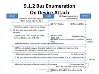
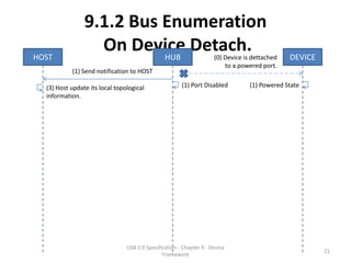

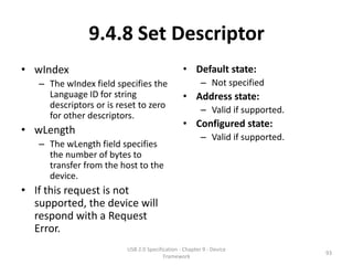
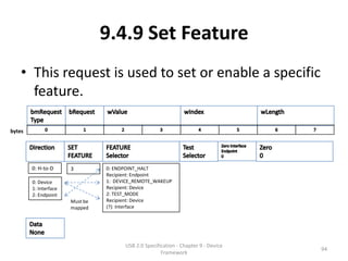
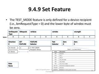
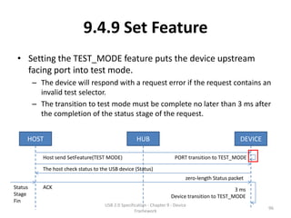


The document summarizes Chapter 9 of the USB 2.0 Specification regarding the USB device framework. It describes USB device states including attached, powered, default, address, configured, and suspended. It also outlines generic USB device operations such as dynamic attachment/removal, address assignment, configuration, data transfer, and power management. Key concepts covered include bus enumeration, alternate interface settings, power budgeting, and remote wakeup capability.