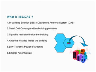
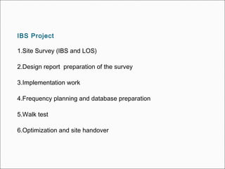
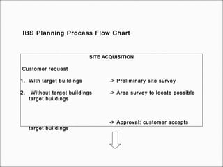
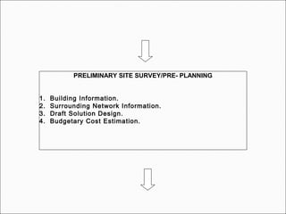
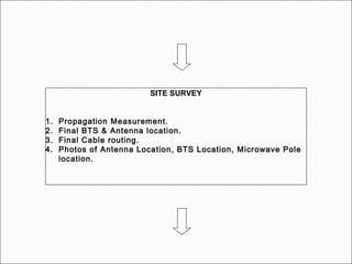
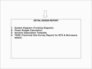
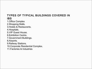
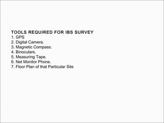
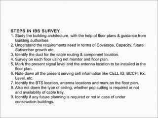
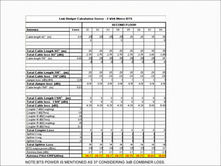
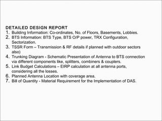
IBS TRAINING
PREPARED BY:
Tempus Telcosys
 IBS SURVEYIBS SURVEY
 LINK BUDGET CALCULATIONLINK BUDGET CALCULATION
 IMPLEMENTATIONIMPLEMENTATION
 QUALITY CHECKLISTQUALITY CHECKLIST
 VENDOR HANDLING TIPSVENDOR HANDLING TIPS
 REPEATERREPEATER
 BASIC OF LOS SURVEYBASIC OF LOS SURVEY
 BASIC OF RF SURVEYBASIC OF RF SURVEY
CONTENTSCONTENTS
What is IBS/DAS ?
1.In-building Solution (IBS) / Distributed Antenna System (DAS)
2.Small Cell Coverage within building premises
3.Signal is restricted inside the building
4.Antenna installed inside the building
5.Low Transmit Power of Antenna
6.Smaller Antenna size
What drives the need for IBS ?
1. Demand of Continuous coverage
2. Indoor Activities generating high traffic
3. Poor indoor coverage of outdoor sites
4. Offloading outdoor cells with high utilization
5. Improvement of Network Performance.
IBS Project
1.Site Survey (IBS and LOS)
2.Design report preparation of the survey
3.Implementation work
4.Frequency planning and database preparation
5.Walk test
6.Optimization and site handover
PLANNING PROCESS
Survey, IBS Planning
IBS Planning Process Flow Chart
SITE ACQUISITION
Customer request
1. With target buildings -> Preliminary site survey
2. Without target buildings -> Area survey to locate possible
target buildings
-> Approval: customer accepts
target buildings
PRELIMINARY SITE SURVEY/PRE- PLANNING
1. Building Information.
2. Surrounding Network Information.
3. Draft Solution Design.
4. Budgetary Cost Estimation.
SITE SURVEY
1. Propagation Measurement.
2. Final BTS & Antenna location.
3. Final Cable routing.
4. Photos of Antenna Location, BTS Location, Microwave Pole
location.
DETAIL DESIGN REPORT
1. System Diagram (Trunking Diagram).
2. Power Budget Calculation.
3. Solution Description Template.
4. TSSR (Technical Site Survey Report) for BTS & Microwave
details.
TYPES OF TYPICAL BUILDINGS COVERED IN
IBS
1.Office Complex
2.Shopping Malls.
3.Hotels & Restaurants.
4.Hospitals.
5.VIP Guest House.
6.Exhibition Centre.
7.Government Buildings.
8.Airports.
9.Railway Stations.
10.Corporate Residential Complex.
11.Factories & Industries
IBS SURVEY & PRE-PLANNING
TOOLS REQUIRED FOR IBS SURVEY
1. GPS
2. Digital Camera.
3. Magnetic Compass.
4. Binoculars.
5. Measuring Tape.
6. Net Monitor Phone.
7. Floor Plan of that Particular Site
STEPS IN IBS SURVEY
1. Study the building architecture, with the help of floor plans & guidance from
Building authorities
2. Understand the requirements need in terms of Coverage, Capacity, future
Subscriber growth etc.
3. Identify the duct for the cable routing & component location.
4. Survey on each floor using net monitor and floor plan.
5. Mark the present signal level and the antenna location to be installed in the
floor plan.
6. Note down all the present serving cell information like CELL ID, BCCH, Rx.
Level, etc.
7. Identify the BTS location, antenna locations and mark on the floor plan.
8. Also not down the type of ceiling, whether pop cutting is required or not
and availability of cable tray.
9. Identify if any future planning is required or not in case of under
construction buildings.
LOS SURVEY
TAKE LAT – LONG BY GPS
ASK FOR FAR END TO SURVEY CO ORDINATOR
DECIDE TOWER HEIGHT( e. g POLE,RTT, GBT )REQUIREMENT
( ALSO CONSIDER CUSTOMER SPECIFICATION , NOT MENDATORY )
CHECK POSSIBILITY OF CABLE ROUTING UPTO BTS LOCATION
IF PCM CABLE OR A-BTS IS REQUIRED FOR TX ,THEN MAKE NOTE THAT PCM CABLE LENGTH
IS NOT EXCEEDING BY THAT OF GIVEN SPECIFICATION( UPTO 250 M).
( DO NOT COMPROMISE WITH BTS LOCATION IT AFFECTS POWER CALCUTAION )
MAKE TERRACE LAY OUT
INDOOR PROPOGATION
 Indoor channels are different from traditional mobile radio channels in
two different ways
• The distances covered are much smaller
• The variability of the environment is much greater for a much
smaller range of Tx-Rx separation distances.
 The propagation inside a building is influenced by
• Layout of the building
• Construction materials
 Typical building type
• Sports arena, residential home, factory,...
 Indoor propagation is dominated by the same mechanisms as outdoor
• reflection, scattering, diffraction.
 However, conditions are much more variable
• Doors/windows open or not
 The mounting place of antenna
• On the wall, ceiling, etc.
• The level of floors
 In building path loss factors
• Partition losses (same floor)
• Partition losses between floors
PARTITION LOSSES
 There are two kind of partition at the same floor:
• Hard partitions: the walls of the rooms
• Soft partitions: moveable partitions that does not span to the
ceiling
• The path loss depends on the type of the partitions
PARTITION LOSSES BETWEEN FLOORS
 The losses between floors of a building are determined by
• External dimensions and materials of the building
• Type of construction used to create floors
• External surroundings
• Number of windows
• Presence of tinting on windows
ANTENNA SYSTEM USED IN IBS
Antennas Distributed Via Coax Feeder Network
This is the most simplified method used in IBS. It has some advantage like
low cost, flexibility in the
Design when shaping the coverage area, robust and well proven technique
Leaky Cable
This type is mainly used in Train tunnels, where it is tough to install with Coax
feeder network. It also has flexible design but it is costly
ULTRAMINI SITE
2+0
SEC 1
SP2
5m
SP1
5m
5m
15m
5m
10m
15m
10m
10m
15m
SP3
SP4
10m
10m
10m
5m
10m
15m
10m
10m
5m
5m
10m
SP5
SP6
SP7
SP8
OA1
OA2
OA3
OA4
OA5
OA6
OA7
OA8
OA9
OA10
OA11
OA12
PA1
PA2
EXAMPLE
OA2
OA3
OA4
OA5
OA6
OA7
OA8
OA11
OA12
OA1
PA1
PA2
OA9
OA10
SADDLE WORK
POP CUTTING
REQUIRE
POP CUTTING
REQUIRE
LINK BUDGET CALCULATION
IT IS BASICALLY FOR POWER THAT REQUIRED AT ANTENNA END.IT DEPENDS ON THE COMPONENTS
THAT HAS BEEN USED FROM BTS TO ANTENNA THAT IS ERP( EFFECTIVE RADIATED POWER ).
LIST OF COMPONENTS WITH LOSSES ARE AS FOLLOWS::
EIRP( Effective Isotropic Radiated Power )= ERP( Effective Radiated Power ) + Gain of that component
We generally deal with EIRP ( Effective Isotropic Radiated Power ),which is defined below.
1) SPLITTERS
2) COUPLERS
3) CABLES
4) ANTENNAS
5) COMBINER
6) JUMPER CABLE
1) SPLITTERS::
2 WAY2 WAY -3.25-3.25
3 WAY3 WAY -5.05-5.05
4 WAY4 WAY -6.25-6.25
TYPE LOSS (dB)
Generally 3 types of splitters are used in IBS which are as follows.
1) SPLITTERS ( Continue )::
2 WAY 3 WAY 4 WAY
2) COUPLERS::
7 dB7 dB
-7-7 -1.5-1.5
10 dB10 dB
-10-10 -0.5-0.5
15 dB15 dB
-15-15 -0.3-0.3
TYPE LOSS AT
COUPLE PORT (dB)
LOSS AT
THROUGH PORT (dB)
NOTE: Ideally there should be 0 dB loss at through port. But there is always some loss, which is
mentioned in table.
2) COUPLERS ( Continue )::
INPUT
COUPLED PORT
THROUGH PORT
3) CABLES::
½ ‘’( LDF4-50 A)½ ‘’( LDF4-50 A)
-0.11-0.11
7/8 ‘’( LDF5-50 A )7/8 ‘’( LDF5-50 A )
-0.06-0.06
1-5/8’’ ( LDF7-50 A )1-5/8’’ ( LDF7-50 A )
-0.03-0.03
TYPE LOSS (dB per meter)
3) CABLES ( Continue )::
4) ANTENNAS::
Generally 3 types of antenna are used in IBS, which are as follows.
OMNI ANTENNAOMNI ANTENNA
22
PANEL ANTENNAPANEL ANTENNA
77
FLAT PATCH OMNIFLAT PATCH OMNI
ANTENNAANTENNA 55
TYPE Gain (dBi )
4) ANTENNAS ( Continue )::
OMNI ANTENNA
4) ANTENNAS ( Continue )::
PANEL ANTENNA
FLAT PATCH OMNI ANTENNA ( Vendor : Kaweri )
4) ANTENNAS ( Continue )::
12 cm
12 cm
5) COMBINER::
A combiner is the device that enables several transmitters to transmitter from the same antenna.
HYBRID COMBINER( 2 I/P,1HYBRID COMBINER( 2 I/P,1
O/P )O/P ) 3 dB3 dB
TYPE LOSS
A
N
T
E
N
N
A
TX 1
TX 2
e. g TRX
6) LINK BUDGET CALCULATION :: Example with Trunking Diagram:
NOTE:BTS POWER IS MENTIONED AS 37 CONSIDERING 3dB COMBINER LOSS.
6) DIFFERENT CONNECTOR USED IN IMPLEMENTATION:
( 1 ) ½ N MALE CONNECTOR( L4PNM-RC )
To connect female port of other component like our antennas and splitter.
Connect with ½ cable
Connect with antenna port
Or splitter port.
( 2 ) ½ N FEMALE CONNECTOR( L4PNF-RC )
Connect with ½ cable
Connect with male port like
7/8 to ½ inch connector
Or Kaveri combiner
To connect male port of other component like 7/8 to ½ connector.
( 3 ) 7/8 to ½ inch CONNECTOR( L5PNM-RC )
Connect with 7/8 cable( LDF 5-50A )
Connect with female port like
Our antannas and splitter
To connect female port of 7/8 cable at one side and female port of ½ cable or splitter
To connect female port of 7/8 cable at one side and BTS port or jumper cable
( 4 ) DIN Male for LDF5-50 A 7/8 inch Cable( L5PDM-RPC )
Connect with 7/8 cable( LDF 5-50A )
Connect with female port of
jumper cable or directly to
Port of BTS which is
Generally at the top of Ultra BTS
( 5 ) EXTERNAL COMBINER(AVANTEL)
Female Port
Female Port
Female Port
( 6 ) EXTERNAL COMBINER(KAVERI)
Female Port
Female Port
Female Port
( 6 ) EXTERNAL COMBINER(KAVERI)
( 7 ) EXTERNAL JUMPER CABLE
AT BTS END
AT COMBIER END
THIS PORT HAS SIZE SAME AS 7/8 CABLE
7) BTS Types:
Generally 3 types of BTS
Available.
1) Ultra BTS
Cabinet Max. power Demand:1.8KVVAC / 1.5KVADCNominal Voltage:230AC/-48VDC
Configuration: 4+4+4
Power: 43 dBm
2) METRO BTS
85cm
35cm
25cm
Configuration: 2+2
Power: 40 dBm
SECTOR’S JUMPER CABLE
MW CABLE FOR CONNECTIVITY
3) ULTRA MINI BTS
It looks same as Ultra BTS.
Configuration: 2+2
Power: 43 dBm
DETAILED DESIGN REPORT
1. Building Information: Co-ordinates, No. of Floors, Basements, Lobbies.
2. BTS Information: BTS Type, BTS O/P power, TRX Configuration,
Sectorization.
3. TSSR Form – Transmission & RF details if planned with outdoor sectors
also)
4. Trunking Diagram - Schematic Presentation of Antenna to BTS connection
via different components like, splitters, combiners & couplers.
5. Link Budget Calculations – EIRP calculation at all antenna ports,
considering all the losses.
6. Planned Antenna Location with coverage area.
7. Bill of Quantity - Material Requirement for the Implementation of DAS.
REPEATER :
Generally used where capacity required is low.
It amplifies and converts weak signal into stronger signal by adding some gain to it.
There are 2 types of repeaters.
1) BAND SELECTIVE:
It amplifies and boost frequency of particular BAND
2) FREQUENCY SELECTIVE:
It amplifies and boost particular frequencies only (Generally 2 / 3 frequency.
TYPICAL REPEATER INSTALLATION
PICK UP ANTENNA(HIGHLY DIRECTIONAL )
NEARER SITE
INDOOR REPEATERCONNECTED TO PEAK
UP ANTENNA
CONNECTED TO ANTENNA
POWER: 2W GENERALLY.( 33 dBm )
BAND SELECTIVE
IBS IMPLEMENTATION
TYPICAL IBS INSTALLATION
GENERAL IMPLEMENTATION ISSUE IN IBS
 OPEN CONNECTION
Antenna, splitter, coupler port is open
 COUPLER
Couple port/through port is reversed
Input port/through port is reversed
 LABELING
All the splitters and couplers should be labeled for easy identification
 ANTENNA PLACEMENT OR ORIENTATIONS IS NOT AS PER PLAN
Shift in antennas if any due to route / customer problem.
 THERE IS NO PROPER SADDLING, TYING OF CABLES
No Saddling/tying done on site, typical requirement is as follows
i.e., every 1mtr or 1.5mtr cable is to be tied
 REQUIREMENT OF EXTRA MATERIAL
Clamps FOR Antennas/cable
VENDOR HANDLING
1. Handover site to vendor with all details like work permission, material
storage
space, proper cable routing.
2. Generate MRF for delivery of material to this site.
3. Ask vendor for daily update.
4. Must visit site 2-3 day in week.
5. Ask all details after completion of full site.
6. Get the material details from the vendor
7. Get the BOM (Bill of Material) from the vendor and generate cam Form
for
the site after reconciling the material
IMPLIMENTATION AUDIT
Visit site daily if possible otherwise 2-3 day in week
Check installation is as par plan or change
Decide any changes in antenna location (if require according to
aesthetic,
permission, cable routing etc..)
IBS IMPLEMENTATION QUALITY STANDARDS.
1. No Extra Cable is left rolled near the BTS Equipment.
2. Feeder Cable and components have to be independently & properly
clamped
(saddling) to the wall or laid over the cable tray .
3. Combiner is clamped and the various cables to and from the
combiner are
secured properly on the Cable tray or Wall mount.
4. Feeder Installation for all the sectors should have appropriate
bending radius
for both 1/2” & 7/8”.
5. Connector have to be weather proofed
6. Feeders & components should be anchored at fixed intervals by
saddling/cable tie
7. Aesthetic rectification should be completed with cleanliness
THANK YOU…

IBS Training

  • 1.
  • 2.
     IBS SURVEYIBSSURVEY  LINK BUDGET CALCULATIONLINK BUDGET CALCULATION  IMPLEMENTATIONIMPLEMENTATION  QUALITY CHECKLISTQUALITY CHECKLIST  VENDOR HANDLING TIPSVENDOR HANDLING TIPS  REPEATERREPEATER  BASIC OF LOS SURVEYBASIC OF LOS SURVEY  BASIC OF RF SURVEYBASIC OF RF SURVEY CONTENTSCONTENTS
  • 3.
    What is IBS/DAS? 1.In-building Solution (IBS) / Distributed Antenna System (DAS) 2.Small Cell Coverage within building premises 3.Signal is restricted inside the building 4.Antenna installed inside the building 5.Low Transmit Power of Antenna 6.Smaller Antenna size
  • 4.
    What drives theneed for IBS ? 1. Demand of Continuous coverage 2. Indoor Activities generating high traffic 3. Poor indoor coverage of outdoor sites 4. Offloading outdoor cells with high utilization 5. Improvement of Network Performance.
  • 5.
    IBS Project 1.Site Survey(IBS and LOS) 2.Design report preparation of the survey 3.Implementation work 4.Frequency planning and database preparation 5.Walk test 6.Optimization and site handover
  • 6.
  • 7.
    IBS Planning ProcessFlow Chart SITE ACQUISITION Customer request 1. With target buildings -> Preliminary site survey 2. Without target buildings -> Area survey to locate possible target buildings -> Approval: customer accepts target buildings
  • 8.
    PRELIMINARY SITE SURVEY/PRE-PLANNING 1. Building Information. 2. Surrounding Network Information. 3. Draft Solution Design. 4. Budgetary Cost Estimation.
  • 9.
    SITE SURVEY 1. PropagationMeasurement. 2. Final BTS & Antenna location. 3. Final Cable routing. 4. Photos of Antenna Location, BTS Location, Microwave Pole location.
  • 10.
    DETAIL DESIGN REPORT 1.System Diagram (Trunking Diagram). 2. Power Budget Calculation. 3. Solution Description Template. 4. TSSR (Technical Site Survey Report) for BTS & Microwave details.
  • 11.
    TYPES OF TYPICALBUILDINGS COVERED IN IBS 1.Office Complex 2.Shopping Malls. 3.Hotels & Restaurants. 4.Hospitals. 5.VIP Guest House. 6.Exhibition Centre. 7.Government Buildings. 8.Airports. 9.Railway Stations. 10.Corporate Residential Complex. 11.Factories & Industries
  • 12.
    IBS SURVEY &PRE-PLANNING
  • 13.
    TOOLS REQUIRED FORIBS SURVEY 1. GPS 2. Digital Camera. 3. Magnetic Compass. 4. Binoculars. 5. Measuring Tape. 6. Net Monitor Phone. 7. Floor Plan of that Particular Site
  • 14.
    STEPS IN IBSSURVEY 1. Study the building architecture, with the help of floor plans & guidance from Building authorities 2. Understand the requirements need in terms of Coverage, Capacity, future Subscriber growth etc. 3. Identify the duct for the cable routing & component location. 4. Survey on each floor using net monitor and floor plan. 5. Mark the present signal level and the antenna location to be installed in the floor plan. 6. Note down all the present serving cell information like CELL ID, BCCH, Rx. Level, etc. 7. Identify the BTS location, antenna locations and mark on the floor plan. 8. Also not down the type of ceiling, whether pop cutting is required or not and availability of cable tray. 9. Identify if any future planning is required or not in case of under construction buildings.
  • 15.
    LOS SURVEY TAKE LAT– LONG BY GPS ASK FOR FAR END TO SURVEY CO ORDINATOR DECIDE TOWER HEIGHT( e. g POLE,RTT, GBT )REQUIREMENT ( ALSO CONSIDER CUSTOMER SPECIFICATION , NOT MENDATORY ) CHECK POSSIBILITY OF CABLE ROUTING UPTO BTS LOCATION IF PCM CABLE OR A-BTS IS REQUIRED FOR TX ,THEN MAKE NOTE THAT PCM CABLE LENGTH IS NOT EXCEEDING BY THAT OF GIVEN SPECIFICATION( UPTO 250 M). ( DO NOT COMPROMISE WITH BTS LOCATION IT AFFECTS POWER CALCUTAION ) MAKE TERRACE LAY OUT
  • 16.
    INDOOR PROPOGATION  Indoorchannels are different from traditional mobile radio channels in two different ways • The distances covered are much smaller • The variability of the environment is much greater for a much smaller range of Tx-Rx separation distances.  The propagation inside a building is influenced by • Layout of the building • Construction materials  Typical building type • Sports arena, residential home, factory,...  Indoor propagation is dominated by the same mechanisms as outdoor • reflection, scattering, diffraction.
  • 17.
     However, conditionsare much more variable • Doors/windows open or not  The mounting place of antenna • On the wall, ceiling, etc. • The level of floors  In building path loss factors • Partition losses (same floor) • Partition losses between floors
  • 18.
    PARTITION LOSSES  Thereare two kind of partition at the same floor: • Hard partitions: the walls of the rooms • Soft partitions: moveable partitions that does not span to the ceiling • The path loss depends on the type of the partitions PARTITION LOSSES BETWEEN FLOORS  The losses between floors of a building are determined by • External dimensions and materials of the building • Type of construction used to create floors • External surroundings • Number of windows • Presence of tinting on windows
  • 19.
    ANTENNA SYSTEM USEDIN IBS Antennas Distributed Via Coax Feeder Network This is the most simplified method used in IBS. It has some advantage like low cost, flexibility in the Design when shaping the coverage area, robust and well proven technique Leaky Cable This type is mainly used in Train tunnels, where it is tough to install with Coax feeder network. It also has flexible design but it is costly
  • 20.
  • 21.
  • 22.
    LINK BUDGET CALCULATION ITIS BASICALLY FOR POWER THAT REQUIRED AT ANTENNA END.IT DEPENDS ON THE COMPONENTS THAT HAS BEEN USED FROM BTS TO ANTENNA THAT IS ERP( EFFECTIVE RADIATED POWER ). LIST OF COMPONENTS WITH LOSSES ARE AS FOLLOWS:: EIRP( Effective Isotropic Radiated Power )= ERP( Effective Radiated Power ) + Gain of that component We generally deal with EIRP ( Effective Isotropic Radiated Power ),which is defined below. 1) SPLITTERS 2) COUPLERS 3) CABLES 4) ANTENNAS 5) COMBINER 6) JUMPER CABLE
  • 23.
    1) SPLITTERS:: 2 WAY2WAY -3.25-3.25 3 WAY3 WAY -5.05-5.05 4 WAY4 WAY -6.25-6.25 TYPE LOSS (dB) Generally 3 types of splitters are used in IBS which are as follows.
  • 24.
    1) SPLITTERS (Continue ):: 2 WAY 3 WAY 4 WAY
  • 25.
    2) COUPLERS:: 7 dB7dB -7-7 -1.5-1.5 10 dB10 dB -10-10 -0.5-0.5 15 dB15 dB -15-15 -0.3-0.3 TYPE LOSS AT COUPLE PORT (dB) LOSS AT THROUGH PORT (dB) NOTE: Ideally there should be 0 dB loss at through port. But there is always some loss, which is mentioned in table.
  • 26.
    2) COUPLERS (Continue ):: INPUT COUPLED PORT THROUGH PORT
  • 27.
    3) CABLES:: ½ ‘’(LDF4-50 A)½ ‘’( LDF4-50 A) -0.11-0.11 7/8 ‘’( LDF5-50 A )7/8 ‘’( LDF5-50 A ) -0.06-0.06 1-5/8’’ ( LDF7-50 A )1-5/8’’ ( LDF7-50 A ) -0.03-0.03 TYPE LOSS (dB per meter)
  • 28.
    3) CABLES (Continue )::
  • 29.
    4) ANTENNAS:: Generally 3types of antenna are used in IBS, which are as follows. OMNI ANTENNAOMNI ANTENNA 22 PANEL ANTENNAPANEL ANTENNA 77 FLAT PATCH OMNIFLAT PATCH OMNI ANTENNAANTENNA 55 TYPE Gain (dBi )
  • 30.
    4) ANTENNAS (Continue ):: OMNI ANTENNA
  • 31.
    4) ANTENNAS (Continue ):: PANEL ANTENNA
  • 32.
    FLAT PATCH OMNIANTENNA ( Vendor : Kaweri ) 4) ANTENNAS ( Continue ):: 12 cm 12 cm
  • 33.
    5) COMBINER:: A combineris the device that enables several transmitters to transmitter from the same antenna. HYBRID COMBINER( 2 I/P,1HYBRID COMBINER( 2 I/P,1 O/P )O/P ) 3 dB3 dB TYPE LOSS A N T E N N A TX 1 TX 2 e. g TRX
  • 34.
    6) LINK BUDGETCALCULATION :: Example with Trunking Diagram:
  • 35.
    NOTE:BTS POWER ISMENTIONED AS 37 CONSIDERING 3dB COMBINER LOSS.
  • 36.
    6) DIFFERENT CONNECTORUSED IN IMPLEMENTATION: ( 1 ) ½ N MALE CONNECTOR( L4PNM-RC ) To connect female port of other component like our antennas and splitter. Connect with ½ cable Connect with antenna port Or splitter port.
  • 37.
    ( 2 )½ N FEMALE CONNECTOR( L4PNF-RC ) Connect with ½ cable Connect with male port like 7/8 to ½ inch connector Or Kaveri combiner To connect male port of other component like 7/8 to ½ connector.
  • 38.
    ( 3 )7/8 to ½ inch CONNECTOR( L5PNM-RC ) Connect with 7/8 cable( LDF 5-50A ) Connect with female port like Our antannas and splitter To connect female port of 7/8 cable at one side and female port of ½ cable or splitter
  • 39.
    To connect femaleport of 7/8 cable at one side and BTS port or jumper cable ( 4 ) DIN Male for LDF5-50 A 7/8 inch Cable( L5PDM-RPC ) Connect with 7/8 cable( LDF 5-50A ) Connect with female port of jumper cable or directly to Port of BTS which is Generally at the top of Ultra BTS
  • 40.
    ( 5 )EXTERNAL COMBINER(AVANTEL) Female Port Female Port Female Port
  • 41.
    ( 6 )EXTERNAL COMBINER(KAVERI) Female Port Female Port Female Port ( 6 ) EXTERNAL COMBINER(KAVERI)
  • 42.
    ( 7 )EXTERNAL JUMPER CABLE AT BTS END AT COMBIER END THIS PORT HAS SIZE SAME AS 7/8 CABLE
  • 43.
    7) BTS Types: Generally3 types of BTS Available. 1) Ultra BTS Cabinet Max. power Demand:1.8KVVAC / 1.5KVADCNominal Voltage:230AC/-48VDC Configuration: 4+4+4 Power: 43 dBm
  • 44.
  • 45.
    SECTOR’S JUMPER CABLE MWCABLE FOR CONNECTIVITY
  • 46.
    3) ULTRA MINIBTS It looks same as Ultra BTS. Configuration: 2+2 Power: 43 dBm
  • 47.
    DETAILED DESIGN REPORT 1.Building Information: Co-ordinates, No. of Floors, Basements, Lobbies. 2. BTS Information: BTS Type, BTS O/P power, TRX Configuration, Sectorization. 3. TSSR Form – Transmission & RF details if planned with outdoor sectors also) 4. Trunking Diagram - Schematic Presentation of Antenna to BTS connection via different components like, splitters, combiners & couplers. 5. Link Budget Calculations – EIRP calculation at all antenna ports, considering all the losses. 6. Planned Antenna Location with coverage area. 7. Bill of Quantity - Material Requirement for the Implementation of DAS.
  • 48.
    REPEATER : Generally usedwhere capacity required is low. It amplifies and converts weak signal into stronger signal by adding some gain to it. There are 2 types of repeaters. 1) BAND SELECTIVE: It amplifies and boost frequency of particular BAND 2) FREQUENCY SELECTIVE: It amplifies and boost particular frequencies only (Generally 2 / 3 frequency.
  • 49.
  • 50.
    PICK UP ANTENNA(HIGHLYDIRECTIONAL ) NEARER SITE
  • 51.
    INDOOR REPEATERCONNECTED TOPEAK UP ANTENNA CONNECTED TO ANTENNA POWER: 2W GENERALLY.( 33 dBm ) BAND SELECTIVE
  • 52.
  • 53.
  • 54.
    GENERAL IMPLEMENTATION ISSUEIN IBS  OPEN CONNECTION Antenna, splitter, coupler port is open  COUPLER Couple port/through port is reversed Input port/through port is reversed  LABELING All the splitters and couplers should be labeled for easy identification  ANTENNA PLACEMENT OR ORIENTATIONS IS NOT AS PER PLAN Shift in antennas if any due to route / customer problem.  THERE IS NO PROPER SADDLING, TYING OF CABLES No Saddling/tying done on site, typical requirement is as follows i.e., every 1mtr or 1.5mtr cable is to be tied  REQUIREMENT OF EXTRA MATERIAL Clamps FOR Antennas/cable
  • 55.
    VENDOR HANDLING 1. Handoversite to vendor with all details like work permission, material storage space, proper cable routing. 2. Generate MRF for delivery of material to this site. 3. Ask vendor for daily update. 4. Must visit site 2-3 day in week. 5. Ask all details after completion of full site. 6. Get the material details from the vendor 7. Get the BOM (Bill of Material) from the vendor and generate cam Form for the site after reconciling the material
  • 56.
    IMPLIMENTATION AUDIT Visit sitedaily if possible otherwise 2-3 day in week Check installation is as par plan or change Decide any changes in antenna location (if require according to aesthetic, permission, cable routing etc..)
  • 57.
    IBS IMPLEMENTATION QUALITYSTANDARDS. 1. No Extra Cable is left rolled near the BTS Equipment. 2. Feeder Cable and components have to be independently & properly clamped (saddling) to the wall or laid over the cable tray . 3. Combiner is clamped and the various cables to and from the combiner are secured properly on the Cable tray or Wall mount. 4. Feeder Installation for all the sectors should have appropriate bending radius for both 1/2” & 7/8”. 5. Connector have to be weather proofed 6. Feeders & components should be anchored at fixed intervals by saddling/cable tie 7. Aesthetic rectification should be completed with cleanliness
  • 58.

Editor's Notes

  • #2 Tempus Telcosys Time is Almighty 05/31/13
  • #3 Time is Almighty Tempus Telcosys 05/31/13
  • #46 Time is Almighty Tempus Telcosys 05/31/13
  • #59 05/31/13 Time is Almighty Tempus Telcosys