Downloaded 2,652 times
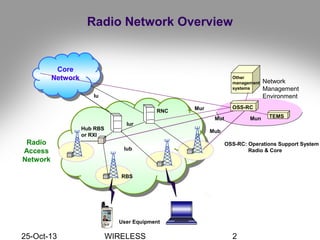
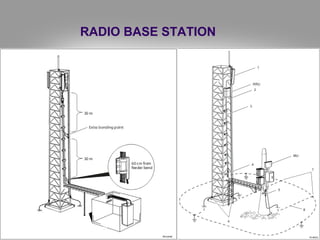
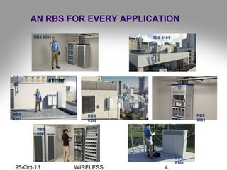
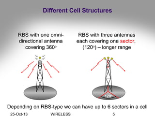
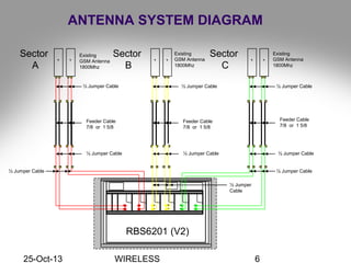
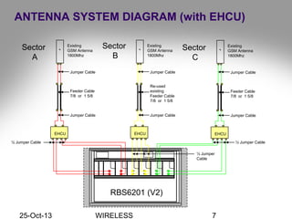
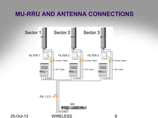
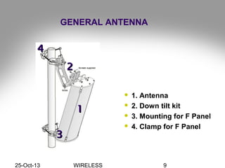
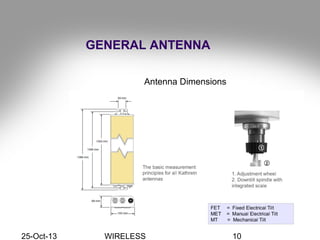
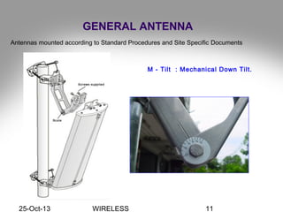
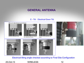
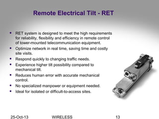
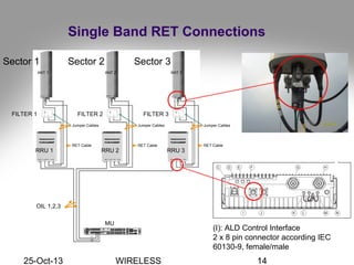
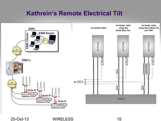
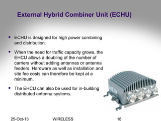
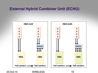
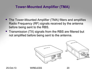
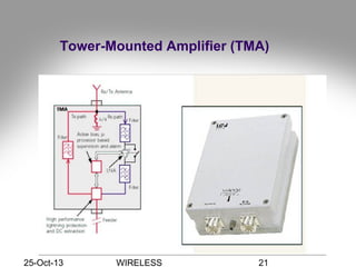
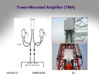
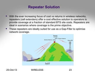
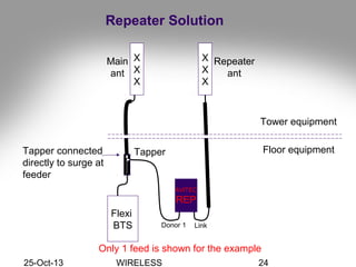
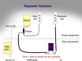
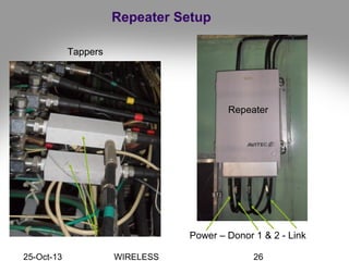
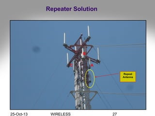
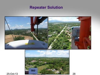
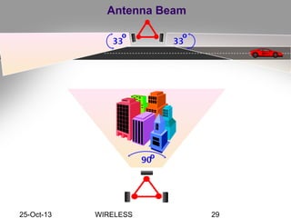
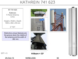
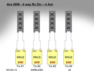
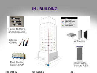
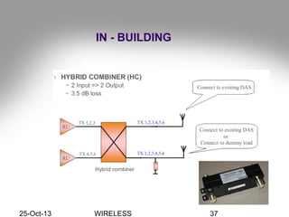
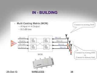
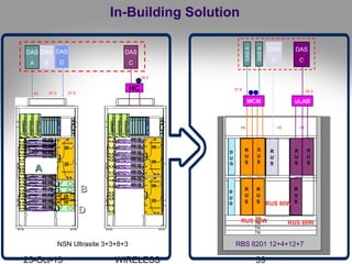
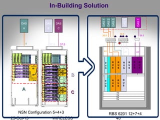
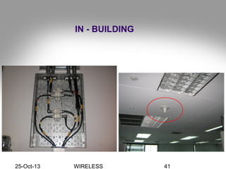
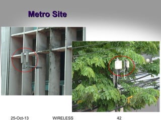
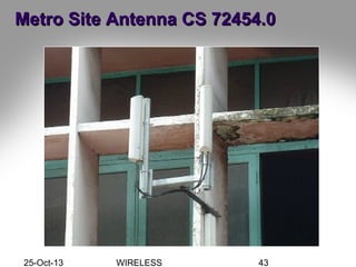
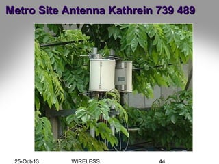
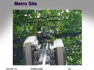
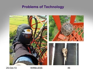
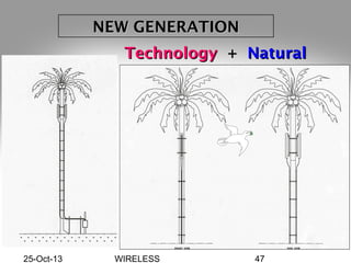
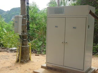


This document discusses wireless communication network project antenna installation engineering. It provides diagrams and explanations of different types of radio base stations, antenna systems, remote electrical tilt systems, external hybrid combiner units, tower-mounted amplifiers, repeater solutions, smart radio concepts, and in-building solutions. Examples of metro site installations are also included. The document concludes with brief discussions of new generation technologies and problems of technology.