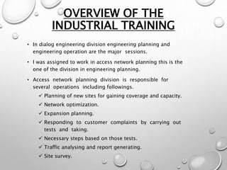
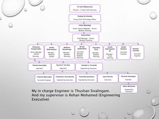
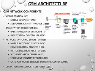
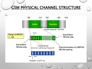
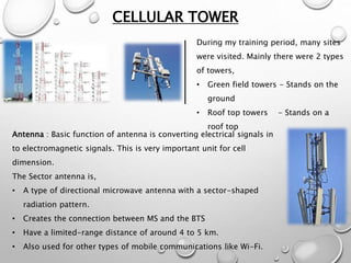
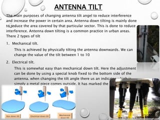
INDUSTRIAL TRAINING 2016
AT
DIALOG AXIATA PLC
GANGASUTHAN M.
EG/2013/2194
ELECTRICAL AND INFORMATION
ENGINEERING
Training period on 04/01/2016 to
27/03/2016
BACKGROUND OF
DIALOG
 Dialog is a subsidiary company of Axiata group berhad
(axiata), a malaysian telecommunication company running its
business over eleven countries in asian region with international
recognition as a major telecommunication service provider.
 A private limited liability company incorporated on 27 august 1993
and subsequently converted to a public limited liability company on
the 26 may 2005.
 Dr. hans wijayasuriya (group chief executive / non-independent,
executive director).
OVERVIEW OF THE
INDUSTRIAL TRAINING
• In dialog engineering division engineering planning and
engineering operation are the major sessions.
• I was assigned to work in access network planning this is the
one of the division in engineering planning.
• Access network planning division is responsible for
several operations including followings.
 Planning of new sites for gaining coverage and capacity.
 Network optimization.
 Expansion planning.
 Responding to customer complaints by carrying out
tests and taking.
 Necessary steps based on those tests.
 Traffic analysing and report generating.
 Site survey.
Dr Hans Wijayasuriya
Director / Group Chief Executive
Pradeep De Almeida
Group Chief Technology Officer
Indika Walpitage
Senior General Manager – Access
Network Planning
Kalum Alwis
Chief Manager – Access
Network Planning
Dhanuska
Illangasinghe
Senior Manager
– Mobile
Planning
Janaka
Rathnasekara
Manager –
Network
Quality
Madhura
Ranathunga
Manager –
Network
Planning
Nirmal
Jayawardana
Assistant
Manager –
Network
Planning
Rasika
Bandara
Assistant
Engineer
Rumesh
Yasintha
Assistant
Engineer
Thajudeen
Girsy
Manager –
Network
Planning
Yasath
Rathnaweera
ge
Manager –
Fixed
Planning
Pubudu Jayasinghe
Specialist
Ruchira P. De Silva
Specialist
Sampath p. Fernando
Engineering Executive
Chamara Wijesinghe
Assistant Engineer
Chamitha K Dushmantha
Engineering Executive
Indranath Jayasekara
Engineering Executive
Jayan Desilva
Executive
Thushan Sivalingam
Engineer
Rehan Mohamed
Engineering
ExecutiveMy in charge Engineer is Thushan Sivalingam.
And my supervisor is Rehan Mohamed (Engineering
Executive)
GSM ARCHITECTURE
GSM NETWORK COMPONENTS
• MOBILE STATION (MS)
• MOBILE EQUIPMENT (ME)
• SUBSCRIBER IDENTITY MODULE (SIM)
• BASE STATION SUBSYSTEM (BSS)
• BASE TRANSCEIVER STATION (BTS)
• BASE STATION CONTROLLER (BSC)
• NETWORK SWITCHING SUBSYSTEM(NSS)
• MOBILE SWITCHING CENTER (MSC)
• HOME LOCATION REGISTER (HLR)
• VISITOR LOCATION REGISTER (VLR)
• AUTHENTICATION CENTER (AUC)
• EQUIPMENT IDENTITY REGISTER (EIR)
• GATE WAY MOBILE SERVICES SWITCHING CENTER (GMSC)
• OPERATION AND SUPPORT SUBSYSTEM (OSS)
GSM PHYSICAL CHANNEL STRUCTURE
CELLULAR TOWER
During my training period, many sites
were visited. Mainly there were 2 types
of towers,
• Green field towers - Stands on the
ground
• Roof top towers - Stands on a
roof top
Antenna : Basic function of antenna is converting electrical signals in
to electromagnetic signals. This is very important unit for cell
dimension.
The Sector antenna is,
• A type of directional microwave antenna with a sector-shaped
radiation pattern.
• Creates the connection between MS and the BTS
• Have a limited-range distance of around 4 to 5 km.
• Also used for other types of mobile communications like Wi-Fi.
ANTENNA TILT
The main purposes of changing antenna tilt angel to reduce interference
and increase the power in certain area. Antenna down tilting is mainly done
to reduce the area covered by that particular sector. This is done to reduce
interference. Antenna down tilting is a common practice in urban areas.
There 2 types of tilt
1. Mechanical tilt.
This is achieved by physically tilting the antenna downwards. We can
change the value of the tilt between 1 to 10
2. Electrical tilt.
This is somewhat easy than mechanical down tilt. Here the adjustment
can be done by using a special knob fixed to the bottom side of the
antenna. when changing the tilt angle there us an indicator which is
simply a metal piece comes outside. It has marked the numbers from 0
to 7 so we have a measurement.
REPEATERS
• In telecommunications, a repeater is an electronic device that receives a
signal and retransmits it at a higher level or higher power, or onto the
other side of an obstruction, so that the signal can cover longer distances.
• There two types of Repeaters
• Outdoor repeater.
• Indoor repeater.
• Outdoor repeater : Outdoor repeaters are mainly use for large outdoor
coverage Area. These kind of repeaters can configure by connecting
with laptop via Ethernet or serial cable. Configurations are done by
using OMT software package.
Configuring Outdoor Repeater
Indoor Repeater(2G & 3G)
• This kind of repeaters are used in IBS. Configuration
is done by connecting laptop via serial cable.
• Receiving power level to the donor antenna is
indicated by orange led.
• These are also use in IBS to establish 2g coverage.
These are preconfigured and only can be change few
parameters by using push buttons and led display.
Indoor repeater installation
• INSTALLATION LOCATION :
• MT ANTENNAS
• ENVIRONMENTAL
• POWERING (AC MAINS SUPPLY)
• GROUNDING REQUIREMENT
• CABLE ROUTING
• MANUAL HANDLING
• WALL MOUNTING
• EQUIPMENT CONNECTIONS
• SERVICE VOLTAGE CONNECTION
• SERVER ANTENNAS
• CONTROL PANEL
CO-CHANNEL INTERFERENCE
• This type of interference is the due to frequency reuse, i.e. Several cells use
the same set of frequency.
• These cells are called co-channel cells.
• Co-channel interference cannot be combated by increasing the power of the
transmitter. This is because an increase in carrier transmit power increases the
interference to neighboring co-channel cells.
• To reduce co-channel interference, co-channel cells must be physically
separated by a minimum distance to provide sufficient isolation due to
propagation or reduce the footprint of the cell.
• Some factors other than reuse distance that influence co-channel interference
are antenna type, directionality, height, site position etc.
ADJACENT-CHANNEL INTERFERENCE
• Interference resulting from signals which are adjacent in frequency to the
desired signal is called adjacent channel interference.
• Adjacent channel interference results from imperfect receiver filters which
allow nearby frequencies to leak into the passband.
• Adjacent channel interference can be minimized through careful filtering
and channel assignments.
FREQUENCY HOPPING
• Frequency hopping is mechanism in which the system changes the
frequency (uplink and downlink) during transmission at regular intervals.
• Frequency hopping parameters :
• MOBILE ALLOCATION LIST (MA)
• HOPPING SEQUENCE NUMBER (HSN)
• MOBILE ALLOCATION INDEX OFFSET (MAIO)
PRELIMINARY ACCEPTANCE TEST (PAT)
Site installations are done by external subcontractors. Before accepting that
by dialog it should be checked for the proper installation. This is called as
preliminary acceptance test. several checkups are done to ensure proper
installation like,
• Proper functionality of alarms.
• Correct VSWR level of feeders. ( ≤1.4 )
• Correct receiving and transmitting power.
• Proper grounding of the site.
• Tilt, height and azimuth of sector antennas as planning division said.
• Proper labeling of cables.
PAT DIAGRAM
DRIVE TEST
Drive test is traditional and best way to verify network performance for new
sites or existing sites. it can be done by drive across targeted routes with
drive test equipment.
The objectives of drive testing are fallowing
• Coverage verification
• New site performance verification and field optimization
• Network problem trouble shooting like drop calls, handover failures poor
coverage patches.
• Quality comparison against competitor networks.
Types of drive tests
• New site drive test
• Bench mark drive test
• Migration driver test
• Route drive test
Equipment need for drive test
• Laptop
• Mobile phone(3g/4g)
• GPS device
• Vehicle (for traveling)
• Analyzing software(we have used NEMO
outdoor)
BASIC PARAMETERS OBSERVE BY NEMO
OUTDOOR
• RX-Level
• The power level corresponds to the average received signal level of
downlink as measured by the mobile station.
• RX-LEVEL(DBM) = EIRP(DBM)- PATH LOSS(DB) and RX- LEVEL always
negative
• RX-LEVEL Range
• UP TO -65 DBM : EXCELLENT
• -65 TO -75 : GOOD
• -75 TO -95 : NORMAL
• <-95 : WEAK
• Reasons for path loss
• Shadowing
• Multipath padding
• Companied signal loss
• RX Quality : The level corresponding to the mobile stations received quality
of downlink signal. normal range is 0 to 4. (In 3G RX replaced by RSCP and
NEMO files about sector information and drive test
results
NEMO files converted in to .kmv file to analise in
CONCLUSION
THANK YOU

Industrial training presentation

  • 1.
    INDUSTRIAL TRAINING 2016 AT DIALOGAXIATA PLC GANGASUTHAN M. EG/2013/2194 ELECTRICAL AND INFORMATION ENGINEERING Training period on 04/01/2016 to 27/03/2016
  • 2.
    BACKGROUND OF DIALOG  Dialogis a subsidiary company of Axiata group berhad (axiata), a malaysian telecommunication company running its business over eleven countries in asian region with international recognition as a major telecommunication service provider.  A private limited liability company incorporated on 27 august 1993 and subsequently converted to a public limited liability company on the 26 may 2005.  Dr. hans wijayasuriya (group chief executive / non-independent, executive director).
  • 3.
    OVERVIEW OF THE INDUSTRIALTRAINING • In dialog engineering division engineering planning and engineering operation are the major sessions. • I was assigned to work in access network planning this is the one of the division in engineering planning. • Access network planning division is responsible for several operations including followings.  Planning of new sites for gaining coverage and capacity.  Network optimization.  Expansion planning.  Responding to customer complaints by carrying out tests and taking.  Necessary steps based on those tests.  Traffic analysing and report generating.  Site survey.
  • 4.
    Dr Hans Wijayasuriya Director/ Group Chief Executive Pradeep De Almeida Group Chief Technology Officer Indika Walpitage Senior General Manager – Access Network Planning Kalum Alwis Chief Manager – Access Network Planning Dhanuska Illangasinghe Senior Manager – Mobile Planning Janaka Rathnasekara Manager – Network Quality Madhura Ranathunga Manager – Network Planning Nirmal Jayawardana Assistant Manager – Network Planning Rasika Bandara Assistant Engineer Rumesh Yasintha Assistant Engineer Thajudeen Girsy Manager – Network Planning Yasath Rathnaweera ge Manager – Fixed Planning Pubudu Jayasinghe Specialist Ruchira P. De Silva Specialist Sampath p. Fernando Engineering Executive Chamara Wijesinghe Assistant Engineer Chamitha K Dushmantha Engineering Executive Indranath Jayasekara Engineering Executive Jayan Desilva Executive Thushan Sivalingam Engineer Rehan Mohamed Engineering ExecutiveMy in charge Engineer is Thushan Sivalingam. And my supervisor is Rehan Mohamed (Engineering Executive)
  • 5.
    GSM ARCHITECTURE GSM NETWORKCOMPONENTS • MOBILE STATION (MS) • MOBILE EQUIPMENT (ME) • SUBSCRIBER IDENTITY MODULE (SIM) • BASE STATION SUBSYSTEM (BSS) • BASE TRANSCEIVER STATION (BTS) • BASE STATION CONTROLLER (BSC) • NETWORK SWITCHING SUBSYSTEM(NSS) • MOBILE SWITCHING CENTER (MSC) • HOME LOCATION REGISTER (HLR) • VISITOR LOCATION REGISTER (VLR) • AUTHENTICATION CENTER (AUC) • EQUIPMENT IDENTITY REGISTER (EIR) • GATE WAY MOBILE SERVICES SWITCHING CENTER (GMSC) • OPERATION AND SUPPORT SUBSYSTEM (OSS)
  • 6.
  • 7.
    CELLULAR TOWER During mytraining period, many sites were visited. Mainly there were 2 types of towers, • Green field towers - Stands on the ground • Roof top towers - Stands on a roof top Antenna : Basic function of antenna is converting electrical signals in to electromagnetic signals. This is very important unit for cell dimension. The Sector antenna is, • A type of directional microwave antenna with a sector-shaped radiation pattern. • Creates the connection between MS and the BTS • Have a limited-range distance of around 4 to 5 km. • Also used for other types of mobile communications like Wi-Fi.
  • 8.
    ANTENNA TILT The mainpurposes of changing antenna tilt angel to reduce interference and increase the power in certain area. Antenna down tilting is mainly done to reduce the area covered by that particular sector. This is done to reduce interference. Antenna down tilting is a common practice in urban areas. There 2 types of tilt 1. Mechanical tilt. This is achieved by physically tilting the antenna downwards. We can change the value of the tilt between 1 to 10 2. Electrical tilt. This is somewhat easy than mechanical down tilt. Here the adjustment can be done by using a special knob fixed to the bottom side of the antenna. when changing the tilt angle there us an indicator which is simply a metal piece comes outside. It has marked the numbers from 0 to 7 so we have a measurement.
  • 9.
    REPEATERS • In telecommunications,a repeater is an electronic device that receives a signal and retransmits it at a higher level or higher power, or onto the other side of an obstruction, so that the signal can cover longer distances. • There two types of Repeaters • Outdoor repeater. • Indoor repeater. • Outdoor repeater : Outdoor repeaters are mainly use for large outdoor coverage Area. These kind of repeaters can configure by connecting with laptop via Ethernet or serial cable. Configurations are done by using OMT software package.
  • 10.
  • 11.
    Indoor Repeater(2G &3G) • This kind of repeaters are used in IBS. Configuration is done by connecting laptop via serial cable. • Receiving power level to the donor antenna is indicated by orange led. • These are also use in IBS to establish 2g coverage. These are preconfigured and only can be change few parameters by using push buttons and led display.
  • 12.
    Indoor repeater installation •INSTALLATION LOCATION : • MT ANTENNAS • ENVIRONMENTAL • POWERING (AC MAINS SUPPLY) • GROUNDING REQUIREMENT • CABLE ROUTING • MANUAL HANDLING • WALL MOUNTING • EQUIPMENT CONNECTIONS • SERVICE VOLTAGE CONNECTION • SERVER ANTENNAS • CONTROL PANEL
  • 13.
    CO-CHANNEL INTERFERENCE • Thistype of interference is the due to frequency reuse, i.e. Several cells use the same set of frequency. • These cells are called co-channel cells. • Co-channel interference cannot be combated by increasing the power of the transmitter. This is because an increase in carrier transmit power increases the interference to neighboring co-channel cells. • To reduce co-channel interference, co-channel cells must be physically separated by a minimum distance to provide sufficient isolation due to propagation or reduce the footprint of the cell. • Some factors other than reuse distance that influence co-channel interference are antenna type, directionality, height, site position etc.
  • 14.
    ADJACENT-CHANNEL INTERFERENCE • Interferenceresulting from signals which are adjacent in frequency to the desired signal is called adjacent channel interference. • Adjacent channel interference results from imperfect receiver filters which allow nearby frequencies to leak into the passband. • Adjacent channel interference can be minimized through careful filtering and channel assignments.
  • 15.
    FREQUENCY HOPPING • Frequencyhopping is mechanism in which the system changes the frequency (uplink and downlink) during transmission at regular intervals. • Frequency hopping parameters : • MOBILE ALLOCATION LIST (MA) • HOPPING SEQUENCE NUMBER (HSN) • MOBILE ALLOCATION INDEX OFFSET (MAIO)
  • 16.
    PRELIMINARY ACCEPTANCE TEST(PAT) Site installations are done by external subcontractors. Before accepting that by dialog it should be checked for the proper installation. This is called as preliminary acceptance test. several checkups are done to ensure proper installation like, • Proper functionality of alarms. • Correct VSWR level of feeders. ( ≤1.4 ) • Correct receiving and transmitting power. • Proper grounding of the site. • Tilt, height and azimuth of sector antennas as planning division said. • Proper labeling of cables. PAT DIAGRAM
  • 17.
    DRIVE TEST Drive testis traditional and best way to verify network performance for new sites or existing sites. it can be done by drive across targeted routes with drive test equipment. The objectives of drive testing are fallowing • Coverage verification • New site performance verification and field optimization • Network problem trouble shooting like drop calls, handover failures poor coverage patches. • Quality comparison against competitor networks.
  • 18.
    Types of drivetests • New site drive test • Bench mark drive test • Migration driver test • Route drive test Equipment need for drive test • Laptop • Mobile phone(3g/4g) • GPS device • Vehicle (for traveling) • Analyzing software(we have used NEMO outdoor)
  • 19.
    BASIC PARAMETERS OBSERVEBY NEMO OUTDOOR • RX-Level • The power level corresponds to the average received signal level of downlink as measured by the mobile station. • RX-LEVEL(DBM) = EIRP(DBM)- PATH LOSS(DB) and RX- LEVEL always negative • RX-LEVEL Range • UP TO -65 DBM : EXCELLENT • -65 TO -75 : GOOD • -75 TO -95 : NORMAL • <-95 : WEAK • Reasons for path loss • Shadowing • Multipath padding • Companied signal loss • RX Quality : The level corresponding to the mobile stations received quality of downlink signal. normal range is 0 to 4. (In 3G RX replaced by RSCP and
  • 20.
    NEMO files aboutsector information and drive test results NEMO files converted in to .kmv file to analise in
  • 21.
  • 22.