Download as PDF, PPTX

![May 2014
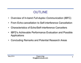
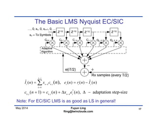
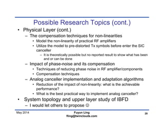
Excess noise in LMS Nyquist EC/SIC
• The coefficients converge towards its optimal value
when n goes to infinity.
– The noise in ri(n) will introduce errors in the coefficients.
• Analysis of MSE of excess error (also valid for LS)
– This results in an error term proportional to the irreducible error
in ei(n), called excess error denoted by eex.
– The MSE of eex can be expressed as:
– normalized step size, e– MSE of irreducible error, L –
the number of coefficients of each sub-canceler
– For EC/SIC eis the received signal power
• Residual echo/SI is proportional to the received signal power
• The residual echo/SI should be 6 dB below the noise level
– Example: 1. Required SNR g= 27 dB and L = 100, m< 10-5
– Example: 2: Required SNR g= 21 dB and L = 40, m< 10-4
(These are very small number – very long time constant)
18Fuyun Ling
fling@twinclouds.com
( / 2)ex
L
2
/ [| | ]nLE x ](https://image.slidesharecdn.com/ibfdpresentation-140604235139-phpapp02/85/Ibfd-presentation-18-320.jpg)
![May 2014
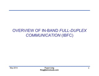
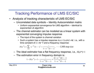
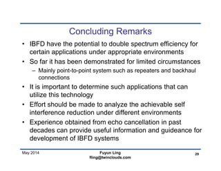
Achievable Performance of IBFD
• Total achievable cancelation can be summarized by the
following empirical formula:
• The first term normally would be in the range of 30-60 dB
– The non-linearity is usually around −30 dB for higher power
amplifiers and may be lower for lower power ones
• Analog canceller is less impacted by the non-linearity in Tx signal
• By establish a non-linearity model, the input to the SIC can be pre-
distorted and less impacted by the non-linearity
– There’s also non-linearity in the receiver side, which is difficult
to compensate
– The channel variation impacts more on the time-varying path,
which yield an interference with lower power
• It may have less impact to the residual interference
22Fuyun Ling
fling@twinclouds.com
, var varmin[( ), ( / ) ]c total NL NL compensation Total ch ch IsolationR R R P P R R ](https://image.slidesharecdn.com/ibfdpresentation-140604235139-phpapp02/85/Ibfd-presentation-22-320.jpg)


The document discusses in-band full-duplex communication (IBFD), focusing on methods for reducing self-interference, including self-interference cancellation (SIC) techniques. It explores the potential advantages of IBFD, such as doubling spectrum efficiency, and highlights its applications in scenarios requiring low link attenuation. Additionally, it identifies limitations and proposes future research areas to enhance IBFD performance and feasibility.


![Multiband Transceivers - [Chapter 4] Design Parameters of Wireless Radios](https://cdn.slidesharecdn.com/ss_thumbnails/ch4-150613070934-lva1-app6892-thumbnail.jpg?width=640&height=640&fit=bounds)


