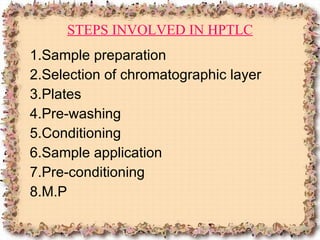
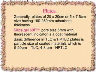
HIGH PERFORMANCE THIN LAYER CHROMATOGRAPHY (HPTLC) Presented By – Mr. Shaise Jacob Faculty, Nirmala College of Pharmacy Muvattupuzha, Kerala, INDIA Email – jacobshaise@gmail.com
INTRODUCTION HPTLC is a sophisticated & automated form of TLC Efficient separation in short time
 
PRINCIPLE Adsorption Advantages of HPTLC Over Other Chromatographic Methods In HPTLC, simultaneous processing of sample and standard – better analytical accuracy & precision Lower analysis time & less cost per analysis HPTLC is very simple In HPTLC, the sample preparation is simple
5. Solvent used in HPTLC needs no prior treatment like filtration & degassing 6. In HPTLC, the M.P consumption for sample is extremely low 7. HPTLC allows the use of corrosive & UV absorbing M.P
STEPS INVOLVED IN HPTLC 1.Sample preparation 2.Selection of chromatographic layer 3.Plates 4.Pre-washing 5.Conditioning 6.Sample application 7.Pre-conditioning 8.M.P
9.Chromatographic development 10.Detection of spots 11.Scanning & documentation
 
Sample preparation For normal phase chromatography using silica gel / alumina pre-coated plates, solvents – non polar  RP chromatography , usually polar solvents Selection of Chromatographic layer »  Depends on the nature of material to be separated Commonly used materials are Silica gel 60F, Alumina, Cellulose etc
Plates Generally, plates of 20  x 20cm or 5 x 7.5cm size having 100-250mm adsorbent thickness. Silica gel 60F 254   pore size 6mm with fluorescent indicator is a coat material Basic difference in TLC & HPTLC plates is particle size of coated materials which is 5-20µm – TLC, 4-8 µm - HPTLC
 
 
Pre-washing »  to remove water vapors »  volatile impurities Which might get trapped in the plates To avoid this, plates are cleaned by using methanol as solvent by ascending or descending etc.
Conditioning Plates activated by placing them in an oven at 120 °C for 15 to 20 minutes. Sample Application Application of 1.0 - 5µl for HPTLC Application carried out by  Linomat applicator  on the plates which give uniform, safe & std. results
PRE-CONDITIONING (Chamber saturation ) For effective separation of sample For RP chromatography – saturate the chamber with methanol or polar solvent MOBILE PHASE Selection of appropriate M.P is based on the trial and error.
Chromatographic development Ascending, descending, horizontal, continuous, gradient, multidimensional… HPTLC – migration distance of 5-6mm is sufficient, after development, plates removed & dried. Common problems encountered during chro. Development are as follows… 1. Tailing:  due to the presence of traces of impurities, this can be reduced by buffering the M.P
2.DIFFUSION:  This is seen as zones on chromatographic plates. This may arise due to non-uniformity of M.P DETECTION OF SPOTS Detection can be done by iodine vapor in iodine chamber. Visual inspection at 254nm of UV region in UV cabinet
Scanning & Documentation HPTLC plates are scanned at selected UV regions WL by the instrument & the detected spots are seen on computer in the form of peaks.  The scanner converts band into peaks & peak height or area is related to the concentration of the substance on the spot.


APPLICATIONS HPTLC rapidly  gaining importance in several fields of science like  Pharmaceuticals analysis Biochemistry Pharmacokinetics studies
 

HPTLC

  • 1.
    HIGH PERFORMANCE THINLAYER CHROMATOGRAPHY (HPTLC) Presented By – Mr. Shaise Jacob Faculty, Nirmala College of Pharmacy Muvattupuzha, Kerala, INDIA Email – jacobshaise@gmail.com
  • 2.
    INTRODUCTION HPTLC isa sophisticated & automated form of TLC Efficient separation in short time
  • 3.
  • 4.
    PRINCIPLE Adsorption Advantagesof HPTLC Over Other Chromatographic Methods In HPTLC, simultaneous processing of sample and standard – better analytical accuracy & precision Lower analysis time & less cost per analysis HPTLC is very simple In HPTLC, the sample preparation is simple
  • 5.
    5. Solvent usedin HPTLC needs no prior treatment like filtration & degassing 6. In HPTLC, the M.P consumption for sample is extremely low 7. HPTLC allows the use of corrosive & UV absorbing M.P
  • 6.
    STEPS INVOLVED INHPTLC 1.Sample preparation 2.Selection of chromatographic layer 3.Plates 4.Pre-washing 5.Conditioning 6.Sample application 7.Pre-conditioning 8.M.P
  • 7.
    9.Chromatographic development 10.Detectionof spots 11.Scanning & documentation
  • 8.
  • 9.
    Sample preparation Fornormal phase chromatography using silica gel / alumina pre-coated plates, solvents – non polar RP chromatography , usually polar solvents Selection of Chromatographic layer » Depends on the nature of material to be separated Commonly used materials are Silica gel 60F, Alumina, Cellulose etc
  • 10.
    Plates Generally, platesof 20 x 20cm or 5 x 7.5cm size having 100-250mm adsorbent thickness. Silica gel 60F 254 pore size 6mm with fluorescent indicator is a coat material Basic difference in TLC & HPTLC plates is particle size of coated materials which is 5-20µm – TLC, 4-8 µm - HPTLC
  • 11.
  • 12.
  • 13.
    Pre-washing » to remove water vapors » volatile impurities Which might get trapped in the plates To avoid this, plates are cleaned by using methanol as solvent by ascending or descending etc.
  • 14.
    Conditioning Plates activatedby placing them in an oven at 120 °C for 15 to 20 minutes. Sample Application Application of 1.0 - 5µl for HPTLC Application carried out by Linomat applicator on the plates which give uniform, safe & std. results
  • 15.
    PRE-CONDITIONING (Chamber saturation) For effective separation of sample For RP chromatography – saturate the chamber with methanol or polar solvent MOBILE PHASE Selection of appropriate M.P is based on the trial and error.
  • 16.
    Chromatographic development Ascending,descending, horizontal, continuous, gradient, multidimensional… HPTLC – migration distance of 5-6mm is sufficient, after development, plates removed & dried. Common problems encountered during chro. Development are as follows… 1. Tailing: due to the presence of traces of impurities, this can be reduced by buffering the M.P
  • 17.
    2.DIFFUSION: Thisis seen as zones on chromatographic plates. This may arise due to non-uniformity of M.P DETECTION OF SPOTS Detection can be done by iodine vapor in iodine chamber. Visual inspection at 254nm of UV region in UV cabinet
  • 18.
    Scanning & DocumentationHPTLC plates are scanned at selected UV regions WL by the instrument & the detected spots are seen on computer in the form of peaks. The scanner converts band into peaks & peak height or area is related to the concentration of the substance on the spot.
  • 19.
  • 20.
  • 21.
  • 22.
    APPLICATIONS HPTLC rapidly gaining importance in several fields of science like Pharmaceuticals analysis Biochemistry Pharmacokinetics studies
  • 23.