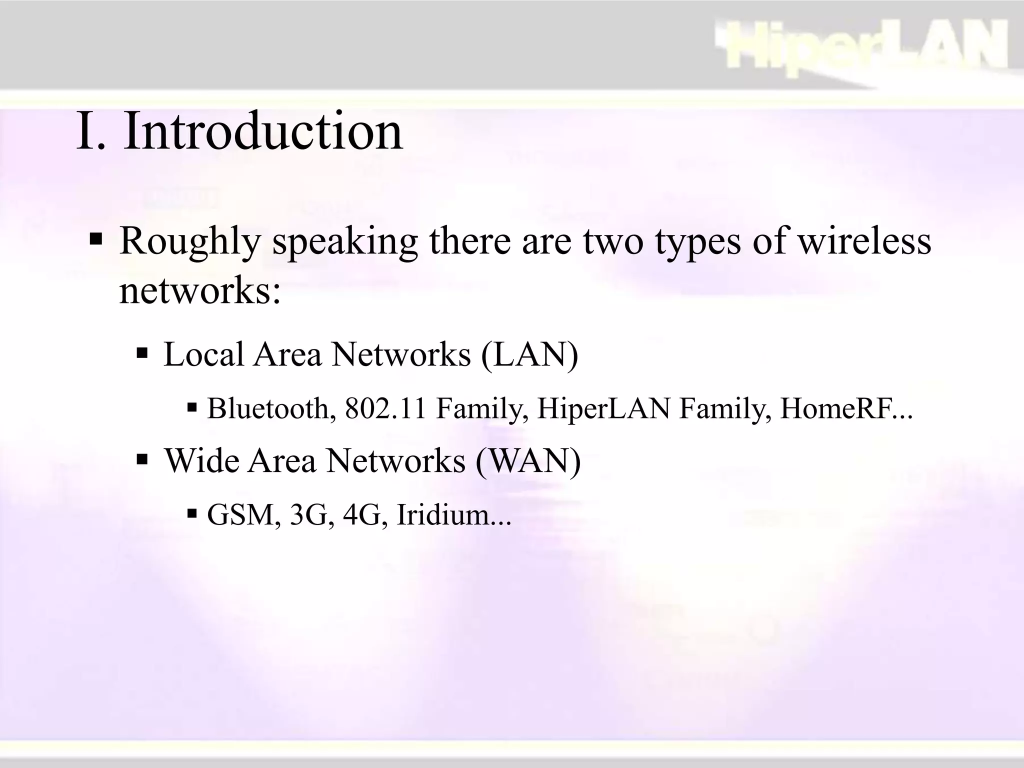
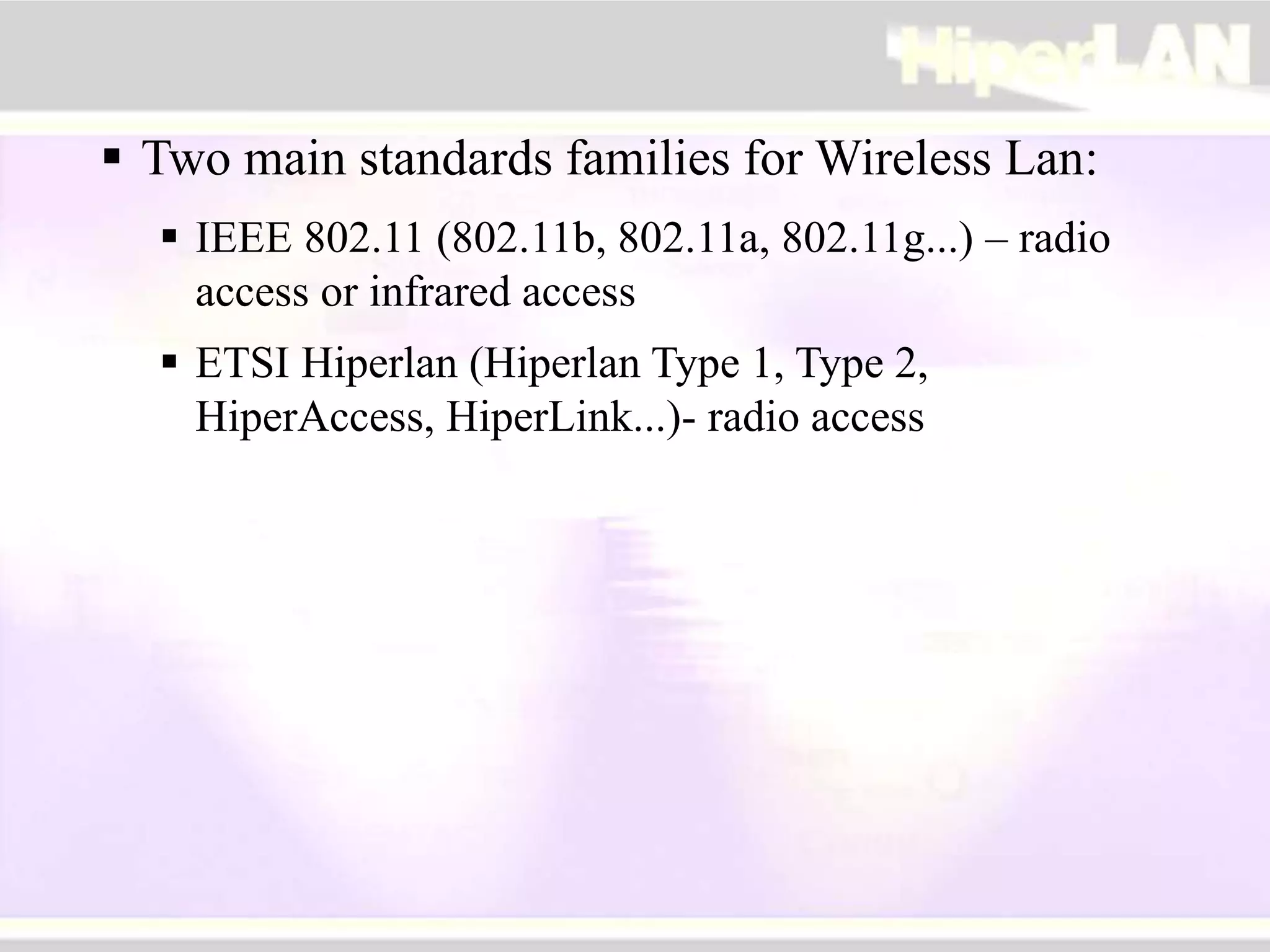
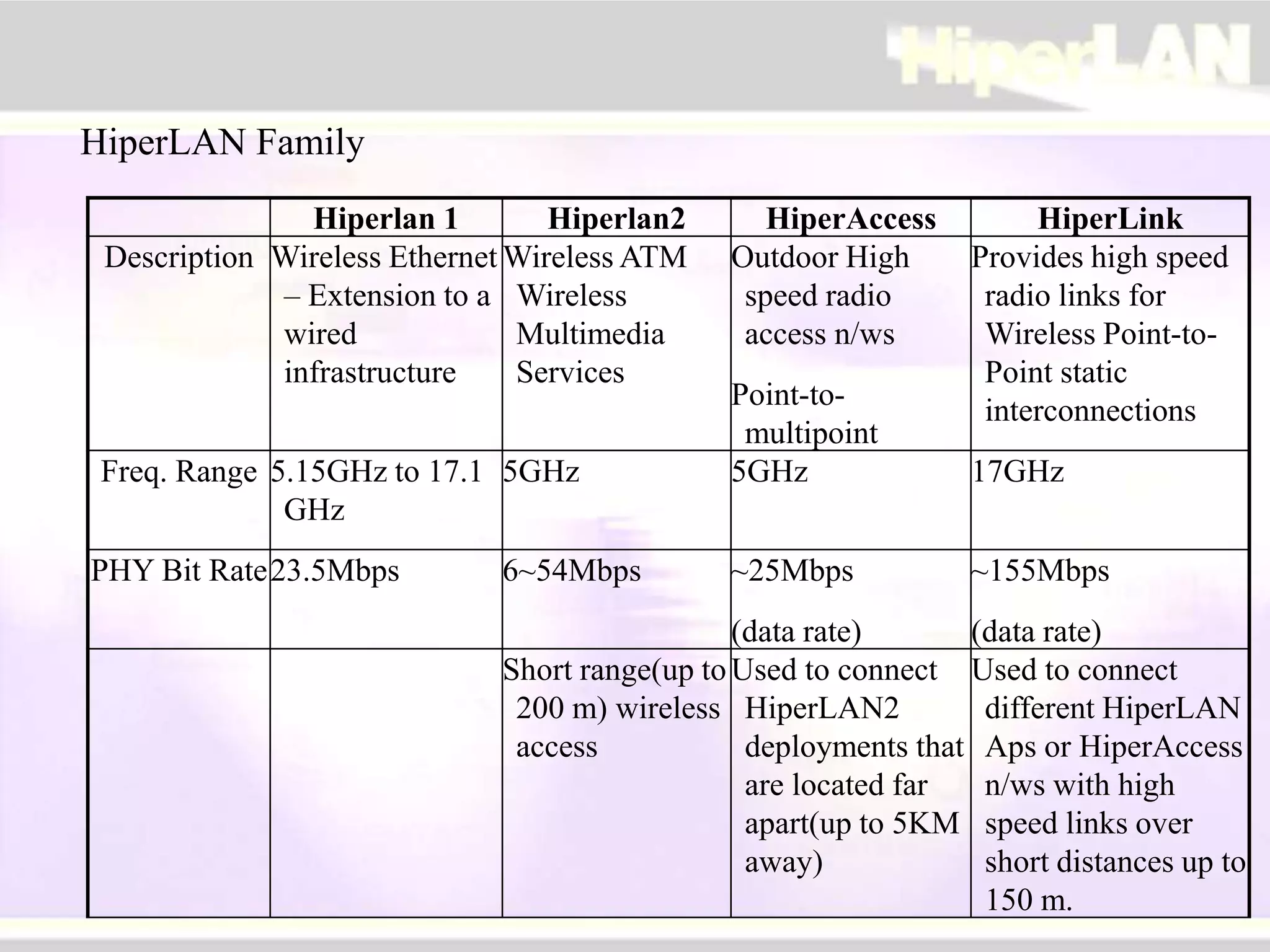
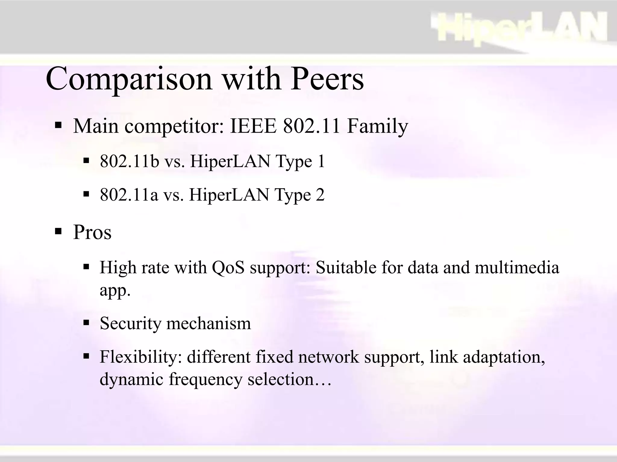
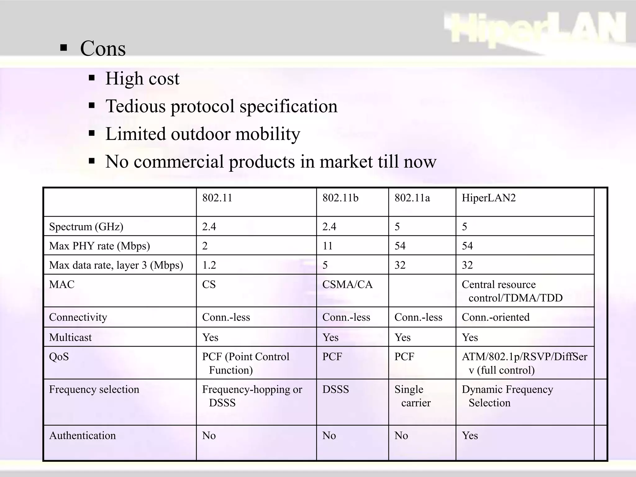
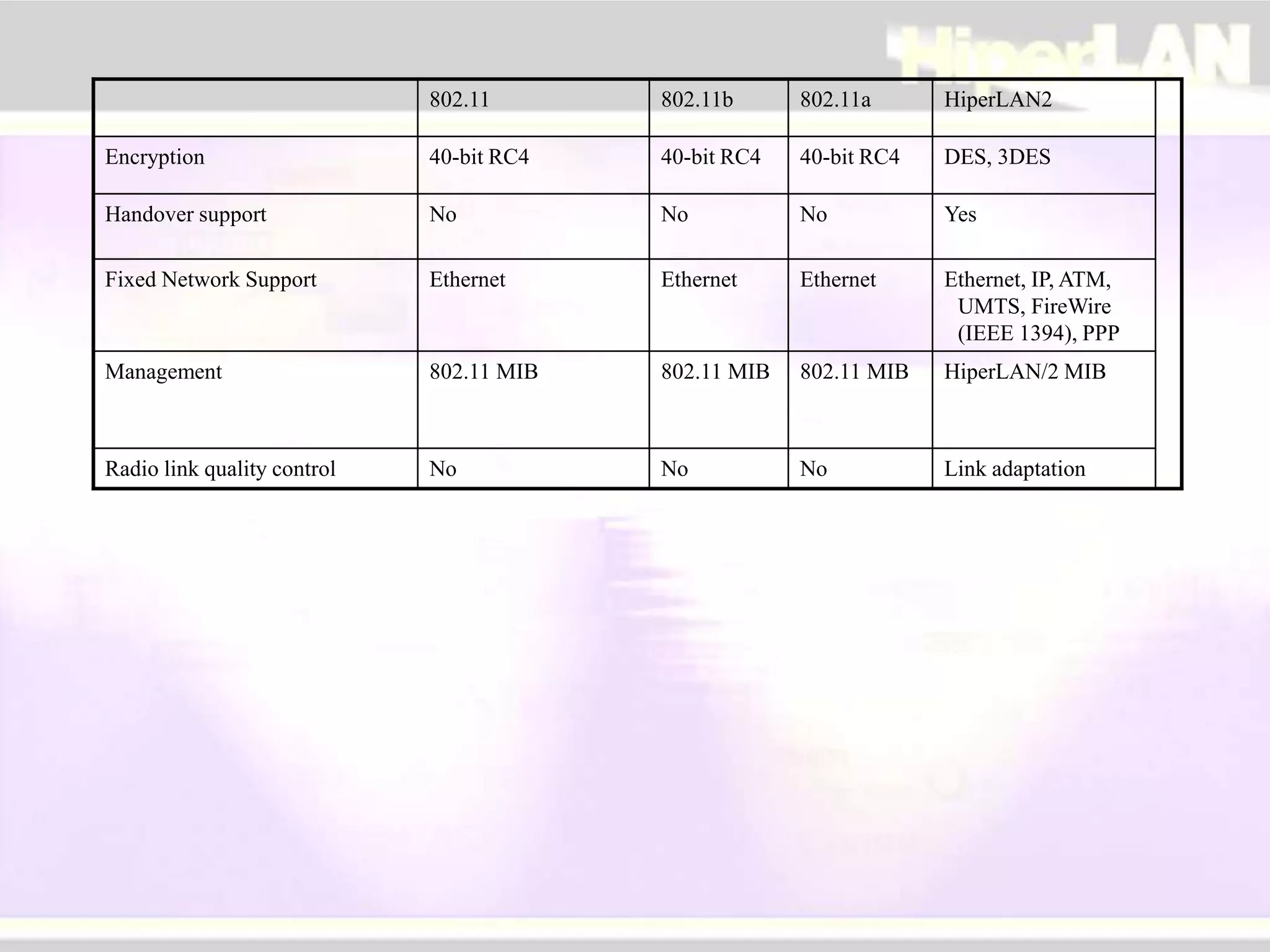
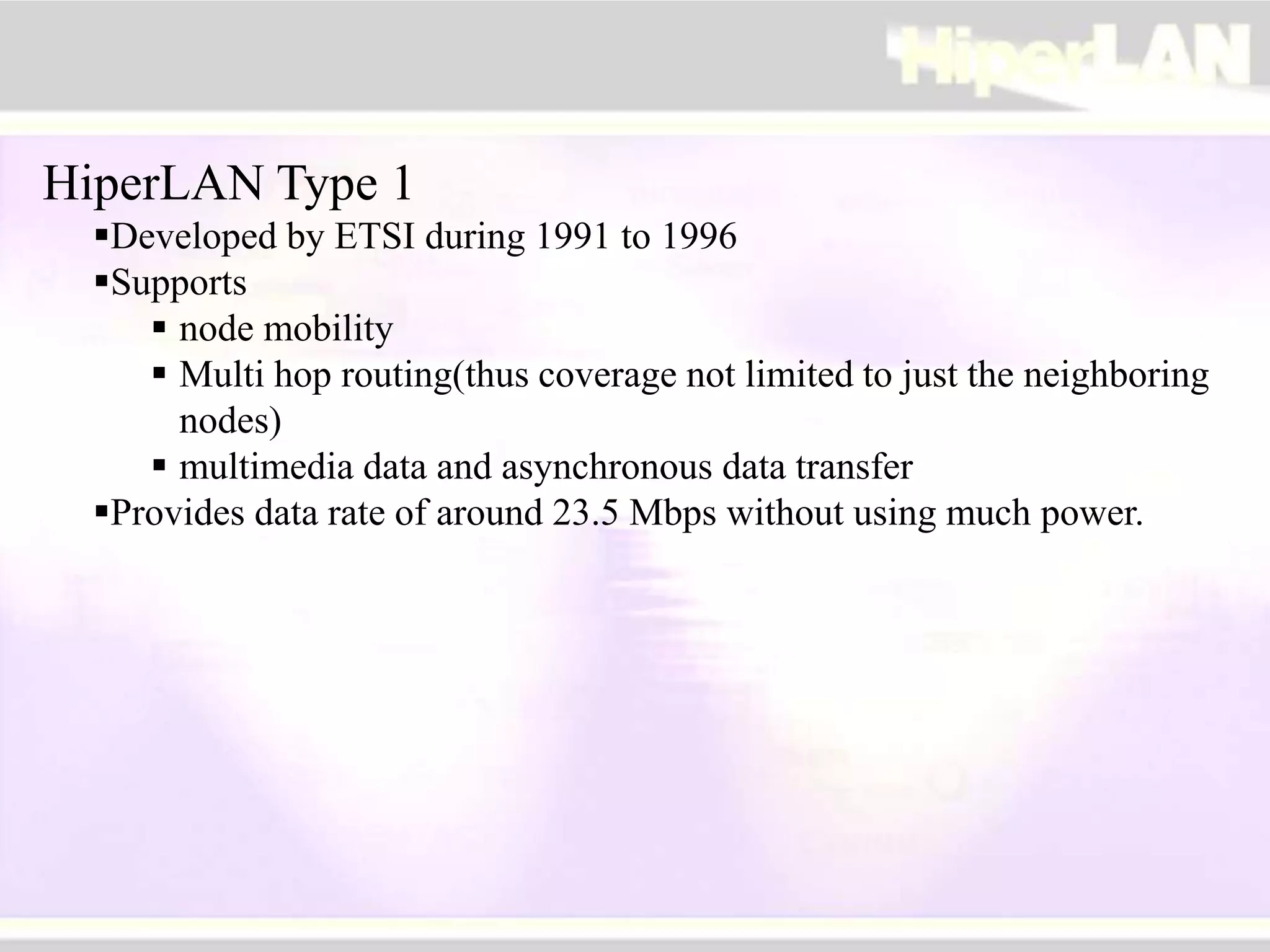
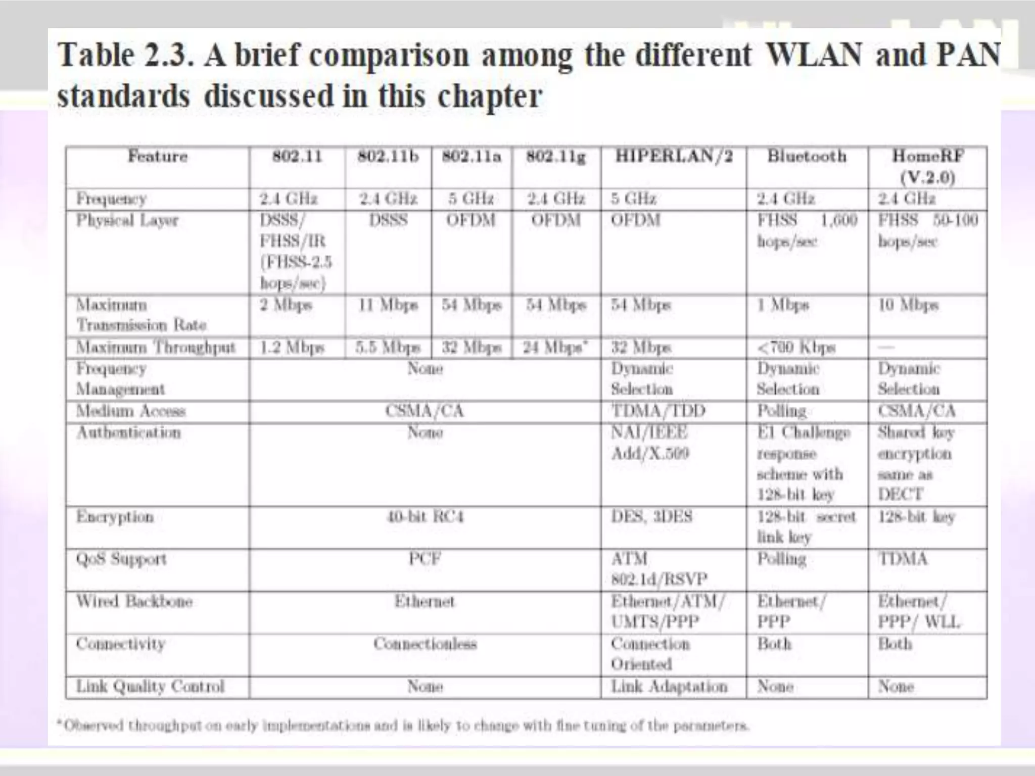
HIPERLAN:
HIgh PErformance Radio
Local Area Networks
I. Introduction
 Roughly speaking there are two types of wireless
networks:
 Local Area Networks (LAN)
 Bluetooth, 802.11 Family, HiperLAN Family, HomeRF...
 Wide Area Networks (WAN)
 GSM, 3G, 4G, Iridium...
 Two main standards families for Wireless Lan:
 IEEE 802.11 (802.11b, 802.11a, 802.11g...) – radio
access or infrared access
 ETSI Hiperlan (Hiperlan Type 1, Type 2,
HiperAccess, HiperLink...)- radio access
Hiperlan 1 Hiperlan2 HiperAccess HiperLink
Description Wireless Ethernet
– Extension to a
wired
infrastructure
Wireless ATM
Wireless
Multimedia
Services
Outdoor High
speed radio
access n/ws
Point-to-
multipoint
Provides high speed
radio links for
Wireless Point-to-
Point static
interconnections
Freq. Range 5.15GHz to 17.1
GHz
5GHz 5GHz 17GHz
PHY Bit Rate23.5Mbps 6~54Mbps ~25Mbps
(data rate)
~155Mbps
(data rate)
Short range(up to
200 m) wireless
access
Used to connect
HiperLAN2
deployments that
are located far
apart(up to 5KM
away)
Used to connect
different HiperLAN
Aps or HiperAccess
n/ws with high
speed links over
short distances up to
150 m.
HiperLAN Family
Fig - The ETSI-BRAN systems
Motivation of HiperLAN
 Massive Growth in wireless and mobile
communications
 Emergence of multimedia applications
 Demands for high-speed Internet access
 Deregulation of the telecommunications industry
Comparison with Peers
 Main competitor: IEEE 802.11 Family
 802.11b vs. HiperLAN Type 1
 802.11a vs. HiperLAN Type 2
 Pros
 High rate with QoS support: Suitable for data and multimedia
app.
 Security mechanism
 Flexibility: different fixed network support, link adaptation,
dynamic frequency selection…
 Cons
 High cost
 Tedious protocol specification
 Limited outdoor mobility
 No commercial products in market till now
802.11 802.11b 802.11a HiperLAN2
Spectrum (GHz) 2.4 2.4 5 5
Max PHY rate (Mbps) 2 11 54 54
Max data rate, layer 3 (Mbps) 1.2 5 32 32
MAC CS CSMA/CA Central resource
control/TDMA/TDD
Connectivity Conn.-less Conn.-less Conn.-less Conn.-oriented
Multicast Yes Yes Yes Yes
QoS PCF (Point Control
Function)
PCF PCF ATM/802.1p/RSVP/DiffSer
v (full control)
Frequency selection Frequency-hopping or
DSSS
DSSS Single
carrier
Dynamic Frequency
Selection
Authentication No No No Yes
802.11 802.11b 802.11a HiperLAN2
Encryption 40-bit RC4 40-bit RC4 40-bit RC4 DES, 3DES
Handover support No No No Yes
Fixed Network Support Ethernet Ethernet Ethernet Ethernet, IP, ATM,
UMTS, FireWire
(IEEE 1394), PPP
Management 802.11 MIB 802.11 MIB 802.11 MIB HiperLAN/2 MIB
Radio link quality control No No No Link adaptation
HiperLAN Type 1
Developed by ETSI during 1991 to 1996
Supports
 node mobility
 Multi hop routing(thus coverage not limited to just the neighboring
nodes)
 multimedia data and asynchronous data transfer
Provides data rate of around 23.5 Mbps without using much power.
HiperLAN Type 1
Physical Layer : its tasks are
• Modulation & De modulation
• Forward error correction mechanisms
• Signal strength measurement
• Synchronization between sender & receiver
• Uses CCA schemes (similar to CSMA/CA) to sense whether the channel
is idle or busy.
MAC sub layer : is responsible for processing the pkts from the higher layers.
And also responsible for
• Forwarding mechanisms
• Power conservation schemes
• Communication confidentiality through encryption & decryption
methods
HiperLAN Type 1
CAC sub layer :
• offers a connectionless data service to the MAC sub layer.
• The MAC layer uses this service to specify a priory called Channel Access
Mechanism(CAM) priority to each pkt/PDU.
• The PDU with highest CAM priority and the least residual time will be
selected for access to the channel.
• The channel access mechanism used is elimination yield non-pre emptive
multiple access(EY-NMPA) mechanism.
• It is dynamic, listen-and-then-talk protocol
• Similar to CSMA/CA
Figure - The operation of EY-NPMA
Four distinct phases : Prioritization, Elimination, Yield and Data
Transmission.
During prioritization, EY-NPMA recognizes five distinct priorities from 0 to
4, with 0 being the highest priority. The cycle begins with each station
sensing the channel for as many slots as the priority of the packet. All
stations that successfully sense the channel as idle for the whole interval
proceed to the next phase – elimination. Those that do not, exit the
contention process and wait for another attempt.
During the elimination phase, each station transmits an energy burst of
random length. As soon as a station finishes bursting, it immediately senses
the channel. If the channel is sensed as idle, the station proceeds to the next
phase; otherwise, it leaves the cycle.
During the yield phase, the stations that survived the two
previous ones, back off for a random number of slots. The
station that backs off for the shortest interval eventually
accesses the channel for data transmission. All other stations
sense the beginning of the transmission and refrain from
transmitting.
During transmission phase, the successful delivery of a data
packet is acknowledged with an ACK packet.
HiperLAN does not conflict with microwave and other kitchen appliances,
which are on 2.4 GHz.
An innovative feature of HIPERLAN 1, which other wireless networks do not
offer, is its ability to forward data packets using several relays.
Relays can extend the communication on the MAC layer beyond the radio
range.
For power conservation, a node may set up a specific wake up pattern. This
pattern determines at what time the node is ready to receive, so that at other
times, the node can turn off its receiver and save energy.
These nodes are called p-savers and need so called p-supporters that contain
information about wake up patterns of all the p-savers they are responsible for.
A p-supporter only forwards data to a p-saver at the moment p-saver is awake.
HiperLAN Type 2
Next generation of HiperLAN family: Proposed by ETSI BRAN
(Broadband Radio Access Networks) in 1999, and is still under
development.
Goal: Providing high-speed (raw bit rate ~54Mbps) communications
access to different broadband core networks and moving terminals
Features: connection-oriented, QoS guaranteed, security mechanism,
handoff(the process of transferring an MT from one channel/AP to
another)
In the figure, it is shown that the core network for HIPERLAN2 is not just
restricted to Ethernet.
Figure - A typical deployment of HIPERLAN/2.
HiperLAN Type 2
• The HIPERLAN/2 protocol stack consists of the physical layer,
convergence layer (CL), and the data link control (DLC) layer.
The Physical Layer
• allows bit rates from 6 Mbps to 54 Mbps using a scheme called link
adaptation.
The CL
• The topmost layer in the HIPERLAN/2 protocol stack is the CL
• converts the higher layer packets into ones of fixed size that can be used by
the lower layers.
• The CL is classified into two types, namely, the packet-based CL and the
cellbased CL. The packet-based CL processes variable-length packets The
cell-basedCL processes fixedsized ATM cells.
HiperLAN Type2
The DLC Layer
• The DLC layer constitutes the logical link between the AP and the MTs.
• This ensures a connection-oriented communication in a HIPERLAN/2
network, in contrast to the connectionless service offered by the IEEE
standards.
• The DLC layer is organized into three functional units, namely,
• the radio link control (RLC) sublayer
• the error control (EC) sublayer – Selective Repeat
• The MAC sublayer – Dynamic TDMA
• The tasks of the RLCcan be summarized as follows.
• Association control function (ACF)
• DLC user connection control (DCC)
• Radio resource control (RRC)
• Dynamic frequency selection
• Handoff
• Power saving
HiperAccess and HiperLink
 In parallel to developing the HIPERLAN Type 2 standards, ETSI BRAN
has started work on standards complementary to HIPERLAN Type 2
Relevant Organizations
Standards body: ETSI (European Telecommunications
Standards Institute, www.etsi.org)
Technology alliance:
HiperLAN2 Global Forum (H2GF, www.hiperlan2.com):
promote HiperLAN Type 2 as a standard, in order to
accelerate its use in business and consumer industries.
OFDM Forum (www.ofdm-forum.com): OFDM is the
cornerstone technology for high-speed wireless LAN such
as HiperLAN.
Industry backers: Texas Instruments, Dell, Bosch, Ericsson,
Nokia,Telia, Xircom…
 Typical application scenarios
 HiperLAN: A complement to present-day wireless
access systems, giving high data rates to end-users in
hot-spot areas.
 Typical app. Environment: Offices, homes, exhibition
halls, airports, train stations, etc.
 Different with Bluetooth, which is mainly used for
linking individual communication devices within the
personal area network
MAC
CAC
PHY
HiperLAN Type 1 Reference Model
PHY
MAC
EC
ACF DCC
RLC
DLC
CL
HiperLAN Type 2 Reference Model
Control Plane User Plane
MAC: Medium Access Sublayer EC: Error Control
CAC: Channel Access Control Sublayer RLC: Radio Link Control
PHY: Physical Layer RRC: Radio Resource Control
DLC: Data Link Control Layer ACF: Association Control Function
CL: Convergence Layer DCC: DLC Connection Control
Architecture
RRC
 Three main control functions
 Association control function (ACF): authentication, key
management, association, disassociation, encryption
 Radio resource control function (RRC): handover, dynamic
frequency selection, mobile terminal alive/absent, power
saving, power control
 DLC user connection control function (DCC): setup and
release of user connections, multicast and broadcast
 Connection-oriented
 After completing association, a mobile terminal may request
one or several DLC connections, with one unique DLC address
corresponding to each DLC connection, thus providing
different QoS for each connection
IV. Conclusion
 Will Hiperlan standards replace 802.11?
 There will be a fight between connection and
connectionless camps Hiperlan2/802.11a
 Current products under development and becoming
available only offer 25Mbps
 Hiperlink 155Mbps data rates still some way off
 Wireless: Useful as an adjunct to the wired world
 Bluetooth is a short-range wireless technology standard that is
used for exchanging data between fixed and mobile devices over
short distances and building personal area networks (PANs).
 IEEEhas approved a Bluetooth-based standard (IEEE 802.15.1)
 Bluetooth employs radio frequency (RF) technology for
communication.
 Bluetooth operates at frequencies between 2.402 and 2.480 GHz,
or 2.400 and 2.4835 GHz.
 A piconet is an ad hoc network that links a wireless user group of
devices using Bluetooth technology protocols.
 It allows one master device to interconnect with up to seven active
slave devices.
 Some examples of piconets include a cell phone connected to a
computer, a laptop and a Bluetooth-enabled digital camera, or
several PDAs that are connected to each other.
Bluetooth Specifications:
 The Bluetooth specification consists of two parts: core and
profiles.
 The core provides a common data link and physical layer.
 The profiles specifications classify Bluetooth applications into
thirteen types.
 The protocol stack is logically partitioned into three layers:
 the transport protocol group
 radio layer
 baseband layer
 Link manager layer
 logical link control and adaptation layer
 the host controller interface.
 the middleware protocol group
 RFCOMM, SDP, IrDA
 the application group
 Applications
Figure - Bluetooth protocol stack.
Transport Protocol Group:
 This group allow Bluetooth devices to locate each other and to
create, configure, and manage the wireless links.
 Radio (Physical) Layer
 frequency modulation – GFSK
 64 Kbps voice channels
 asynchronous data channels with a peak rate of 1 Mbps.
 The data channels are either asymmetric (in one direction) or symmetric
(in both directions).
 Typical link range: up to 10 m, can be extended to 100 m by increasing
power.
 The key functions of Baseband Layer are frequency hop selection,
connection creation, and medium access control.
 Formation of piconet.
 A Bluetooth device not associated with any piconet is said to be in
standby mode.
.
 A typical piconet
Operational states - the state diagram of Bluetooth communications
 Initially, all the devices would be in the standby mode.
 Then some device (called the master) could begin the inquiry and
get to know the nearby devices and, if needed, join them into its
piconet.
 After the inquiry, the device could formally be joined by paging,
which is a packet-exchange process between the master and a slave
 Once the device finishes getting paged, it enters the connected
state.
 This state has three power-conserving sub-states – hold, sniff, and
park.
 A device in the connected state can participate in the data
transmission
 The channel is divided into time slots, each 625 μs in length. The
time slots are numbered according to the Bluetooth clock of the
piconet master. A time division duplex (TDD) scheme is used
where master and slave alternately transmit.
 The master starts its transmission in even-numbered time slots
only,
 The slave starts its transmission in odd-numbered time slots only.
Scatternets and Issues:
 Piconets may overlap both spatially and temporally.
 Each piconet is characterized by a unique master and hence the
piconets hop independently, each with its own channel hopping
sequence as determined by the respective master.
 As more piconets are added, the probability of collisions
increases, and a degradation in performance results.
 a device can participate in two or more overlaying piconets by the
process of time sharing
 A group of piconets is called a scatternet
A typical scatternet
 Link manager protocol (LMP) is responsible for
 setting and maintaining the properties of the Bluetooth link.
 power management and security management
 minimal QoS support
 Power Management -The Bluetooth units can be in several modes
of operation during the connection state, namely, active mode,
sniff mode, hold mode, and park mode.
 Logical Link Control and Adaptation Protocol (L2CAP) supports
protocol multiplexing
 Bluetooth Security - The authentication of devices is carried out
by means of a challenge response mechanism which is based on a
commonly shared secret link key generated through a user-
provided personal identification number (PIN).
Middleware Protocol Group:
 This group consists of the RFCOMM layer, service discovery
protocol (SDP), IrDA interoperability protocols, telephony control
specification (TCS), and audio.
 The RFCOMM layer presents a virtual serial port to applications.
 The IrDA interoperability protocol is not for communication
between Bluetooth devices and Infrared devices. It is only for the
existing IrDA applications to work on Bluetooth devices without
any changes.
Bluetooth Profiles:
 Two Bluetooth devices can achieve a common functionality only
if both devices support identical profiles.
 For example, a cellular phone and a headset both have to support
the Bluetooth headset profile for the headset to work with the
phone.
 classified into the following four categories
 Generic profiles: The Generic access profile, which is not really an
application, provides a way to establish and maintain secure links
between the master and the slaves.
 Telephony profiles: The cordless telephony profile is designed for three
in- one phones. The Intercom profile supports two-way voice
communication between two Bluetooth devices within range of each
other. The Headset profile specifies how Bluetooth can provide a wireless
connection to a headset (with earphones/microphones) for use with a
computer or a mobile phone.
Bluetooth Profiles:
 classified into the following four categories
 Networking profiles: The LAN Access profile enables Bluetooth devices
to either connect to aLAN through APs or form a small wireless LAN
among themselves
 Serial and object exchange profiles: The serial port profile emulates a
serial line (RS232 and USB serial ports) for (legacy) applications that
require a serial line.
HiperLAN & Bluetooth.ppt

HiperLAN & Bluetooth.ppt

  • 1.
  • 2.
    I. Introduction  Roughlyspeaking there are two types of wireless networks:  Local Area Networks (LAN)  Bluetooth, 802.11 Family, HiperLAN Family, HomeRF...  Wide Area Networks (WAN)  GSM, 3G, 4G, Iridium...
  • 3.
     Two mainstandards families for Wireless Lan:  IEEE 802.11 (802.11b, 802.11a, 802.11g...) – radio access or infrared access  ETSI Hiperlan (Hiperlan Type 1, Type 2, HiperAccess, HiperLink...)- radio access
  • 4.
    Hiperlan 1 Hiperlan2HiperAccess HiperLink Description Wireless Ethernet – Extension to a wired infrastructure Wireless ATM Wireless Multimedia Services Outdoor High speed radio access n/ws Point-to- multipoint Provides high speed radio links for Wireless Point-to- Point static interconnections Freq. Range 5.15GHz to 17.1 GHz 5GHz 5GHz 17GHz PHY Bit Rate23.5Mbps 6~54Mbps ~25Mbps (data rate) ~155Mbps (data rate) Short range(up to 200 m) wireless access Used to connect HiperLAN2 deployments that are located far apart(up to 5KM away) Used to connect different HiperLAN Aps or HiperAccess n/ws with high speed links over short distances up to 150 m. HiperLAN Family
  • 5.
    Fig - TheETSI-BRAN systems
  • 6.
    Motivation of HiperLAN Massive Growth in wireless and mobile communications  Emergence of multimedia applications  Demands for high-speed Internet access  Deregulation of the telecommunications industry
  • 7.
    Comparison with Peers Main competitor: IEEE 802.11 Family  802.11b vs. HiperLAN Type 1  802.11a vs. HiperLAN Type 2  Pros  High rate with QoS support: Suitable for data and multimedia app.  Security mechanism  Flexibility: different fixed network support, link adaptation, dynamic frequency selection…
  • 8.
     Cons  Highcost  Tedious protocol specification  Limited outdoor mobility  No commercial products in market till now 802.11 802.11b 802.11a HiperLAN2 Spectrum (GHz) 2.4 2.4 5 5 Max PHY rate (Mbps) 2 11 54 54 Max data rate, layer 3 (Mbps) 1.2 5 32 32 MAC CS CSMA/CA Central resource control/TDMA/TDD Connectivity Conn.-less Conn.-less Conn.-less Conn.-oriented Multicast Yes Yes Yes Yes QoS PCF (Point Control Function) PCF PCF ATM/802.1p/RSVP/DiffSer v (full control) Frequency selection Frequency-hopping or DSSS DSSS Single carrier Dynamic Frequency Selection Authentication No No No Yes
  • 9.
    802.11 802.11b 802.11aHiperLAN2 Encryption 40-bit RC4 40-bit RC4 40-bit RC4 DES, 3DES Handover support No No No Yes Fixed Network Support Ethernet Ethernet Ethernet Ethernet, IP, ATM, UMTS, FireWire (IEEE 1394), PPP Management 802.11 MIB 802.11 MIB 802.11 MIB HiperLAN/2 MIB Radio link quality control No No No Link adaptation
  • 10.
    HiperLAN Type 1 Developedby ETSI during 1991 to 1996 Supports  node mobility  Multi hop routing(thus coverage not limited to just the neighboring nodes)  multimedia data and asynchronous data transfer Provides data rate of around 23.5 Mbps without using much power.
  • 11.
    HiperLAN Type 1 PhysicalLayer : its tasks are • Modulation & De modulation • Forward error correction mechanisms • Signal strength measurement • Synchronization between sender & receiver • Uses CCA schemes (similar to CSMA/CA) to sense whether the channel is idle or busy. MAC sub layer : is responsible for processing the pkts from the higher layers. And also responsible for • Forwarding mechanisms • Power conservation schemes • Communication confidentiality through encryption & decryption methods
  • 12.
    HiperLAN Type 1 CACsub layer : • offers a connectionless data service to the MAC sub layer. • The MAC layer uses this service to specify a priory called Channel Access Mechanism(CAM) priority to each pkt/PDU. • The PDU with highest CAM priority and the least residual time will be selected for access to the channel. • The channel access mechanism used is elimination yield non-pre emptive multiple access(EY-NMPA) mechanism. • It is dynamic, listen-and-then-talk protocol • Similar to CSMA/CA
  • 13.
    Figure - Theoperation of EY-NPMA
  • 14.
    Four distinct phases: Prioritization, Elimination, Yield and Data Transmission. During prioritization, EY-NPMA recognizes five distinct priorities from 0 to 4, with 0 being the highest priority. The cycle begins with each station sensing the channel for as many slots as the priority of the packet. All stations that successfully sense the channel as idle for the whole interval proceed to the next phase – elimination. Those that do not, exit the contention process and wait for another attempt. During the elimination phase, each station transmits an energy burst of random length. As soon as a station finishes bursting, it immediately senses the channel. If the channel is sensed as idle, the station proceeds to the next phase; otherwise, it leaves the cycle.
  • 15.
    During the yieldphase, the stations that survived the two previous ones, back off for a random number of slots. The station that backs off for the shortest interval eventually accesses the channel for data transmission. All other stations sense the beginning of the transmission and refrain from transmitting. During transmission phase, the successful delivery of a data packet is acknowledged with an ACK packet.
  • 16.
    HiperLAN does notconflict with microwave and other kitchen appliances, which are on 2.4 GHz. An innovative feature of HIPERLAN 1, which other wireless networks do not offer, is its ability to forward data packets using several relays. Relays can extend the communication on the MAC layer beyond the radio range. For power conservation, a node may set up a specific wake up pattern. This pattern determines at what time the node is ready to receive, so that at other times, the node can turn off its receiver and save energy. These nodes are called p-savers and need so called p-supporters that contain information about wake up patterns of all the p-savers they are responsible for. A p-supporter only forwards data to a p-saver at the moment p-saver is awake.
  • 17.
    HiperLAN Type 2 Nextgeneration of HiperLAN family: Proposed by ETSI BRAN (Broadband Radio Access Networks) in 1999, and is still under development. Goal: Providing high-speed (raw bit rate ~54Mbps) communications access to different broadband core networks and moving terminals Features: connection-oriented, QoS guaranteed, security mechanism, handoff(the process of transferring an MT from one channel/AP to another) In the figure, it is shown that the core network for HIPERLAN2 is not just restricted to Ethernet.
  • 18.
    Figure - Atypical deployment of HIPERLAN/2.
  • 19.
    HiperLAN Type 2 •The HIPERLAN/2 protocol stack consists of the physical layer, convergence layer (CL), and the data link control (DLC) layer. The Physical Layer • allows bit rates from 6 Mbps to 54 Mbps using a scheme called link adaptation. The CL • The topmost layer in the HIPERLAN/2 protocol stack is the CL • converts the higher layer packets into ones of fixed size that can be used by the lower layers. • The CL is classified into two types, namely, the packet-based CL and the cellbased CL. The packet-based CL processes variable-length packets The cell-basedCL processes fixedsized ATM cells.
  • 20.
    HiperLAN Type2 The DLCLayer • The DLC layer constitutes the logical link between the AP and the MTs. • This ensures a connection-oriented communication in a HIPERLAN/2 network, in contrast to the connectionless service offered by the IEEE standards. • The DLC layer is organized into three functional units, namely, • the radio link control (RLC) sublayer • the error control (EC) sublayer – Selective Repeat • The MAC sublayer – Dynamic TDMA • The tasks of the RLCcan be summarized as follows. • Association control function (ACF) • DLC user connection control (DCC) • Radio resource control (RRC) • Dynamic frequency selection • Handoff • Power saving
  • 21.
    HiperAccess and HiperLink In parallel to developing the HIPERLAN Type 2 standards, ETSI BRAN has started work on standards complementary to HIPERLAN Type 2
  • 22.
    Relevant Organizations Standards body:ETSI (European Telecommunications Standards Institute, www.etsi.org) Technology alliance: HiperLAN2 Global Forum (H2GF, www.hiperlan2.com): promote HiperLAN Type 2 as a standard, in order to accelerate its use in business and consumer industries. OFDM Forum (www.ofdm-forum.com): OFDM is the cornerstone technology for high-speed wireless LAN such as HiperLAN. Industry backers: Texas Instruments, Dell, Bosch, Ericsson, Nokia,Telia, Xircom…
  • 23.
     Typical applicationscenarios  HiperLAN: A complement to present-day wireless access systems, giving high data rates to end-users in hot-spot areas.  Typical app. Environment: Offices, homes, exhibition halls, airports, train stations, etc.  Different with Bluetooth, which is mainly used for linking individual communication devices within the personal area network
  • 25.
    MAC CAC PHY HiperLAN Type 1Reference Model PHY MAC EC ACF DCC RLC DLC CL HiperLAN Type 2 Reference Model Control Plane User Plane MAC: Medium Access Sublayer EC: Error Control CAC: Channel Access Control Sublayer RLC: Radio Link Control PHY: Physical Layer RRC: Radio Resource Control DLC: Data Link Control Layer ACF: Association Control Function CL: Convergence Layer DCC: DLC Connection Control Architecture RRC
  • 26.
     Three maincontrol functions  Association control function (ACF): authentication, key management, association, disassociation, encryption  Radio resource control function (RRC): handover, dynamic frequency selection, mobile terminal alive/absent, power saving, power control  DLC user connection control function (DCC): setup and release of user connections, multicast and broadcast  Connection-oriented  After completing association, a mobile terminal may request one or several DLC connections, with one unique DLC address corresponding to each DLC connection, thus providing different QoS for each connection
  • 27.
    IV. Conclusion  WillHiperlan standards replace 802.11?  There will be a fight between connection and connectionless camps Hiperlan2/802.11a  Current products under development and becoming available only offer 25Mbps  Hiperlink 155Mbps data rates still some way off  Wireless: Useful as an adjunct to the wired world
  • 28.
     Bluetooth isa short-range wireless technology standard that is used for exchanging data between fixed and mobile devices over short distances and building personal area networks (PANs).  IEEEhas approved a Bluetooth-based standard (IEEE 802.15.1)  Bluetooth employs radio frequency (RF) technology for communication.  Bluetooth operates at frequencies between 2.402 and 2.480 GHz, or 2.400 and 2.4835 GHz.  A piconet is an ad hoc network that links a wireless user group of devices using Bluetooth technology protocols.  It allows one master device to interconnect with up to seven active slave devices.  Some examples of piconets include a cell phone connected to a computer, a laptop and a Bluetooth-enabled digital camera, or several PDAs that are connected to each other.
  • 29.
    Bluetooth Specifications:  TheBluetooth specification consists of two parts: core and profiles.  The core provides a common data link and physical layer.  The profiles specifications classify Bluetooth applications into thirteen types.  The protocol stack is logically partitioned into three layers:  the transport protocol group  radio layer  baseband layer  Link manager layer  logical link control and adaptation layer  the host controller interface.  the middleware protocol group  RFCOMM, SDP, IrDA  the application group  Applications
  • 30.
    Figure - Bluetoothprotocol stack.
  • 31.
    Transport Protocol Group: This group allow Bluetooth devices to locate each other and to create, configure, and manage the wireless links.  Radio (Physical) Layer  frequency modulation – GFSK  64 Kbps voice channels  asynchronous data channels with a peak rate of 1 Mbps.  The data channels are either asymmetric (in one direction) or symmetric (in both directions).  Typical link range: up to 10 m, can be extended to 100 m by increasing power.  The key functions of Baseband Layer are frequency hop selection, connection creation, and medium access control.  Formation of piconet.  A Bluetooth device not associated with any piconet is said to be in standby mode.
  • 32.
  • 33.
    Operational states -the state diagram of Bluetooth communications
  • 34.
     Initially, allthe devices would be in the standby mode.  Then some device (called the master) could begin the inquiry and get to know the nearby devices and, if needed, join them into its piconet.  After the inquiry, the device could formally be joined by paging, which is a packet-exchange process between the master and a slave  Once the device finishes getting paged, it enters the connected state.  This state has three power-conserving sub-states – hold, sniff, and park.  A device in the connected state can participate in the data transmission  The channel is divided into time slots, each 625 μs in length. The time slots are numbered according to the Bluetooth clock of the piconet master. A time division duplex (TDD) scheme is used where master and slave alternately transmit.
  • 35.
     The masterstarts its transmission in even-numbered time slots only,  The slave starts its transmission in odd-numbered time slots only. Scatternets and Issues:  Piconets may overlap both spatially and temporally.  Each piconet is characterized by a unique master and hence the piconets hop independently, each with its own channel hopping sequence as determined by the respective master.  As more piconets are added, the probability of collisions increases, and a degradation in performance results.  a device can participate in two or more overlaying piconets by the process of time sharing  A group of piconets is called a scatternet
  • 36.
  • 37.
     Link managerprotocol (LMP) is responsible for  setting and maintaining the properties of the Bluetooth link.  power management and security management  minimal QoS support  Power Management -The Bluetooth units can be in several modes of operation during the connection state, namely, active mode, sniff mode, hold mode, and park mode.  Logical Link Control and Adaptation Protocol (L2CAP) supports protocol multiplexing  Bluetooth Security - The authentication of devices is carried out by means of a challenge response mechanism which is based on a commonly shared secret link key generated through a user- provided personal identification number (PIN).
  • 38.
    Middleware Protocol Group: This group consists of the RFCOMM layer, service discovery protocol (SDP), IrDA interoperability protocols, telephony control specification (TCS), and audio.  The RFCOMM layer presents a virtual serial port to applications.  The IrDA interoperability protocol is not for communication between Bluetooth devices and Infrared devices. It is only for the existing IrDA applications to work on Bluetooth devices without any changes.
  • 39.
    Bluetooth Profiles:  TwoBluetooth devices can achieve a common functionality only if both devices support identical profiles.  For example, a cellular phone and a headset both have to support the Bluetooth headset profile for the headset to work with the phone.  classified into the following four categories  Generic profiles: The Generic access profile, which is not really an application, provides a way to establish and maintain secure links between the master and the slaves.  Telephony profiles: The cordless telephony profile is designed for three in- one phones. The Intercom profile supports two-way voice communication between two Bluetooth devices within range of each other. The Headset profile specifies how Bluetooth can provide a wireless connection to a headset (with earphones/microphones) for use with a computer or a mobile phone.
  • 40.
    Bluetooth Profiles:  classifiedinto the following four categories  Networking profiles: The LAN Access profile enables Bluetooth devices to either connect to aLAN through APs or form a small wireless LAN among themselves  Serial and object exchange profiles: The serial port profile emulates a serial line (RS232 and USB serial ports) for (legacy) applications that require a serial line.