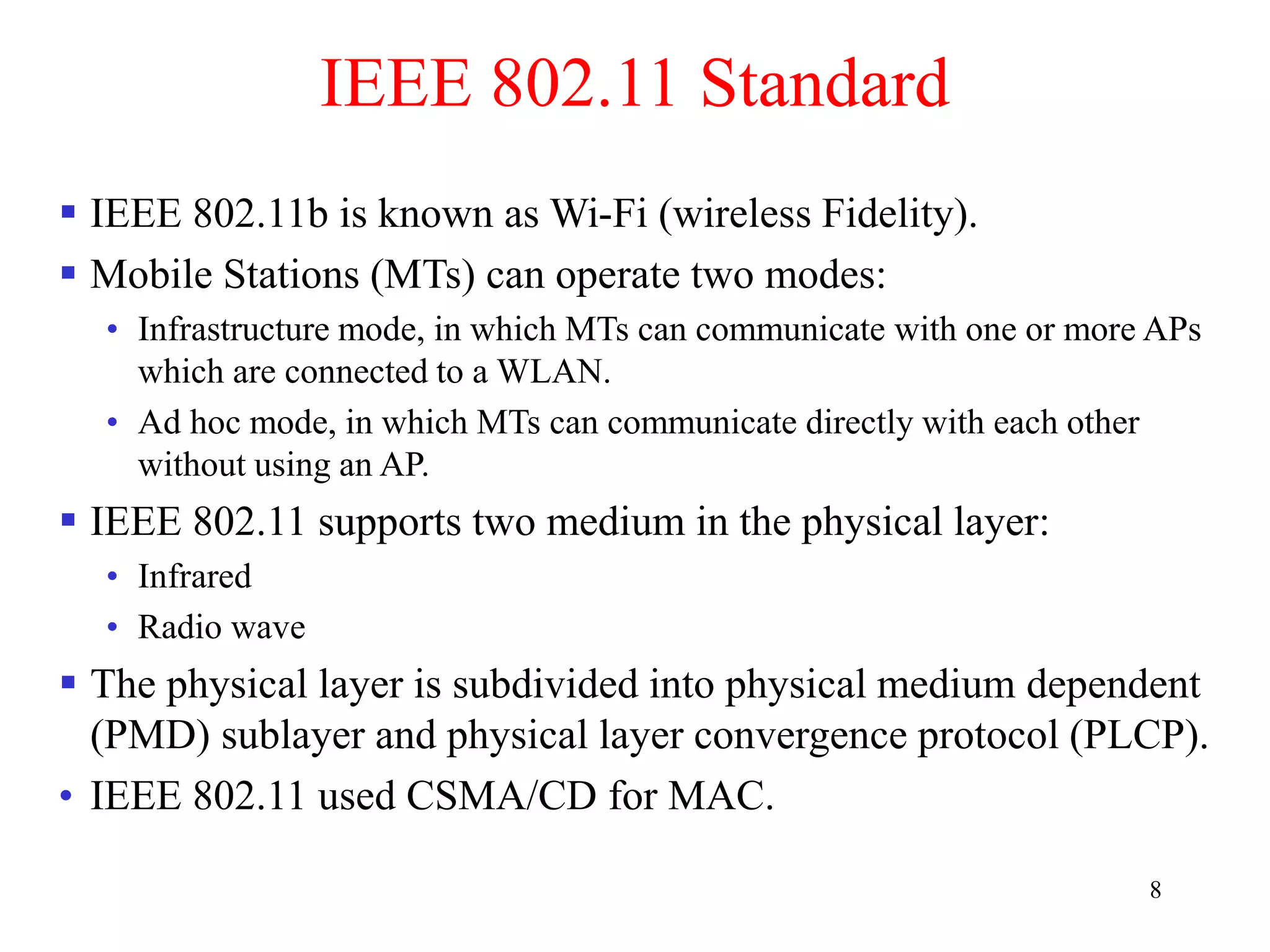
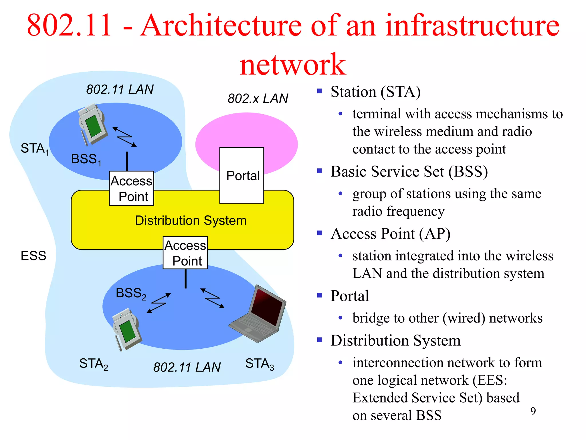
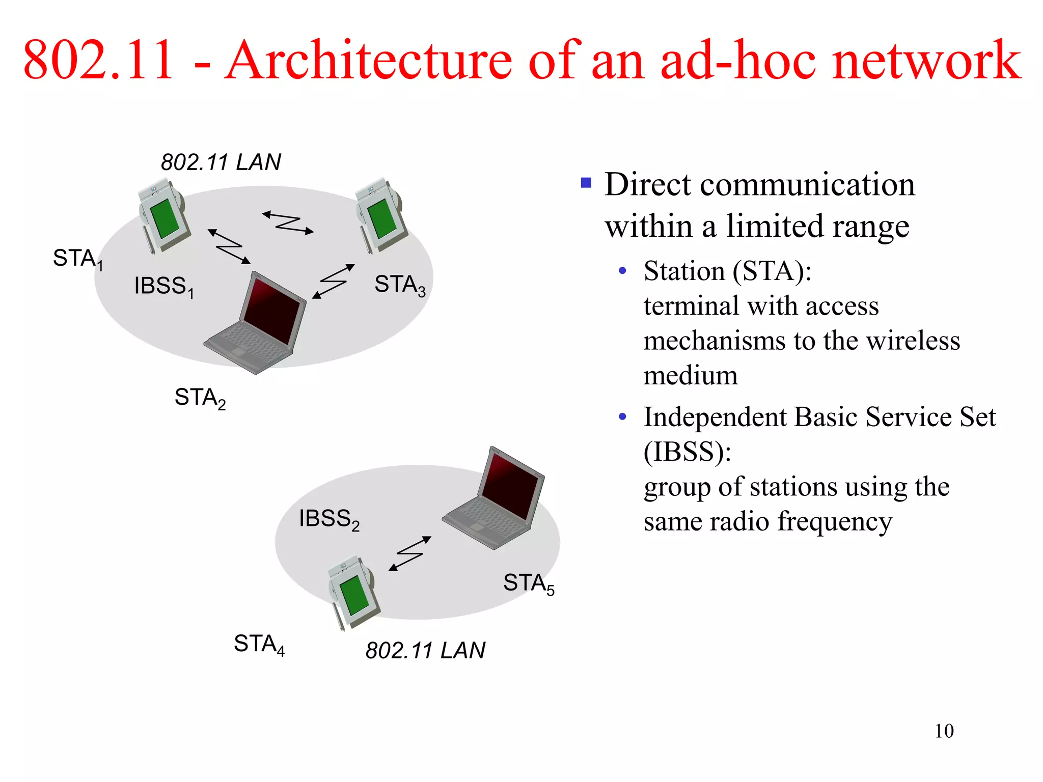
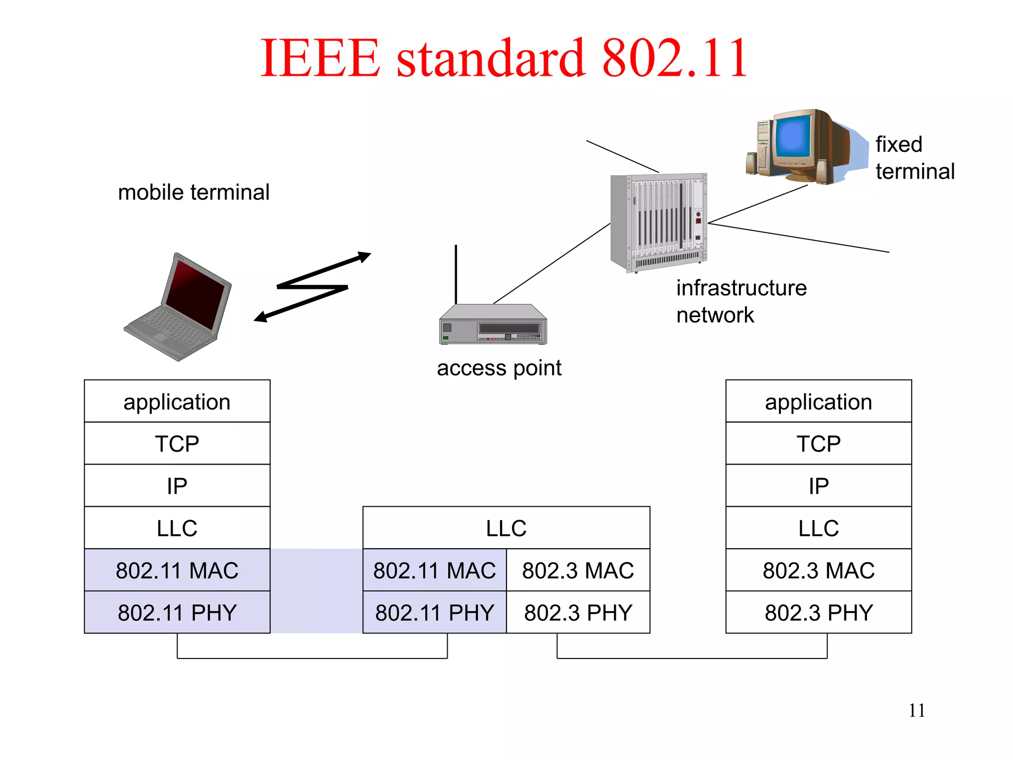
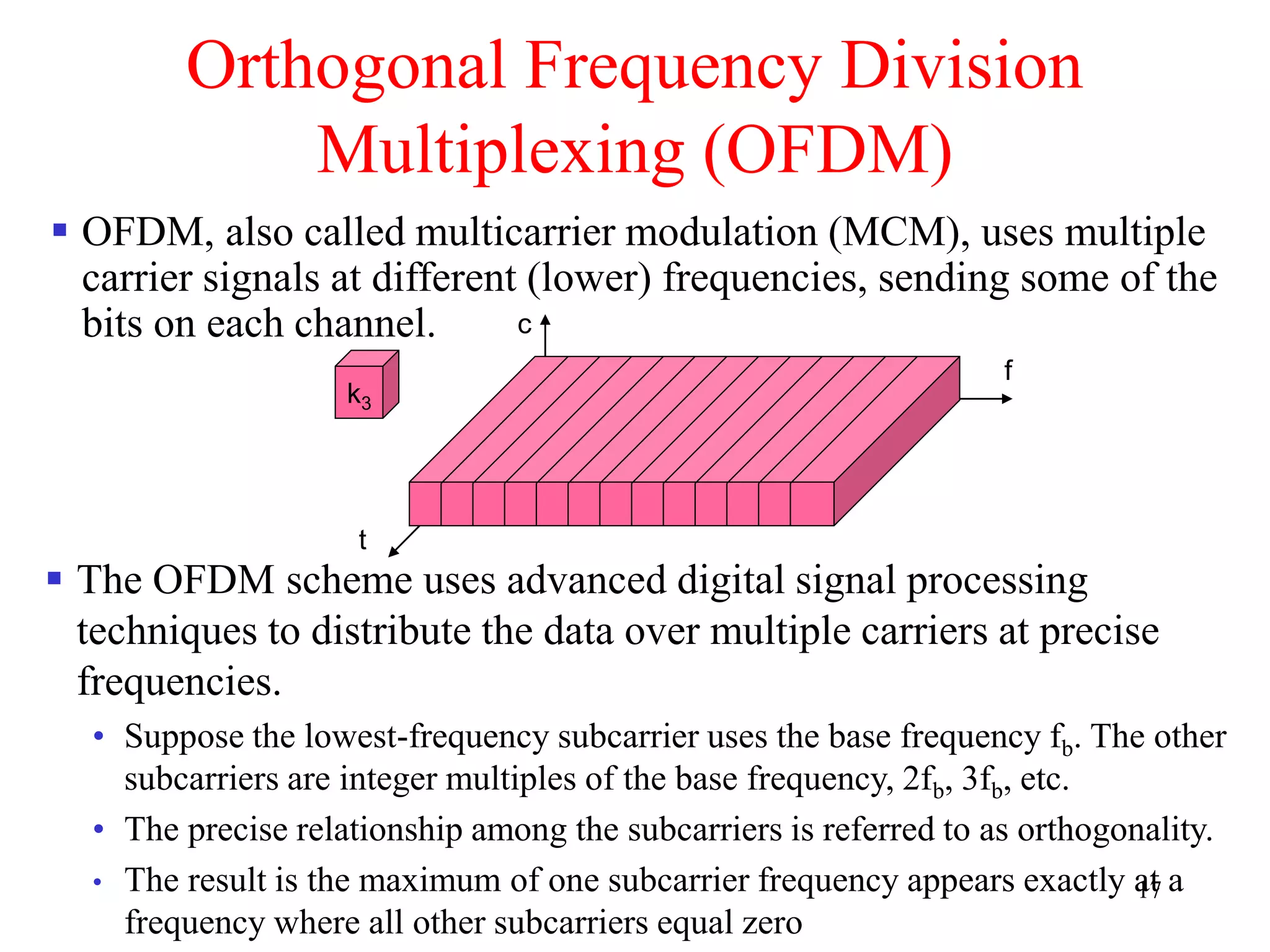
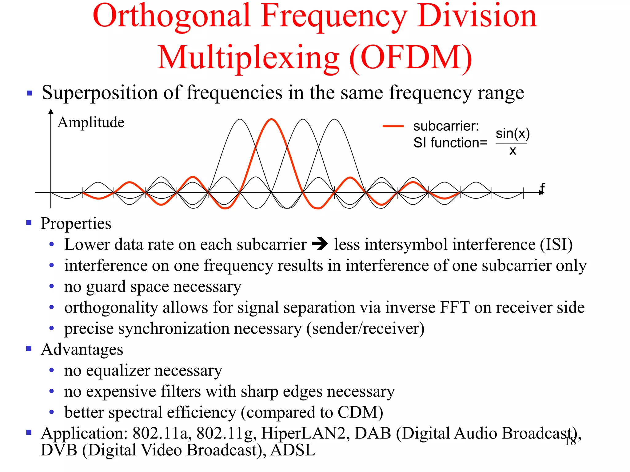
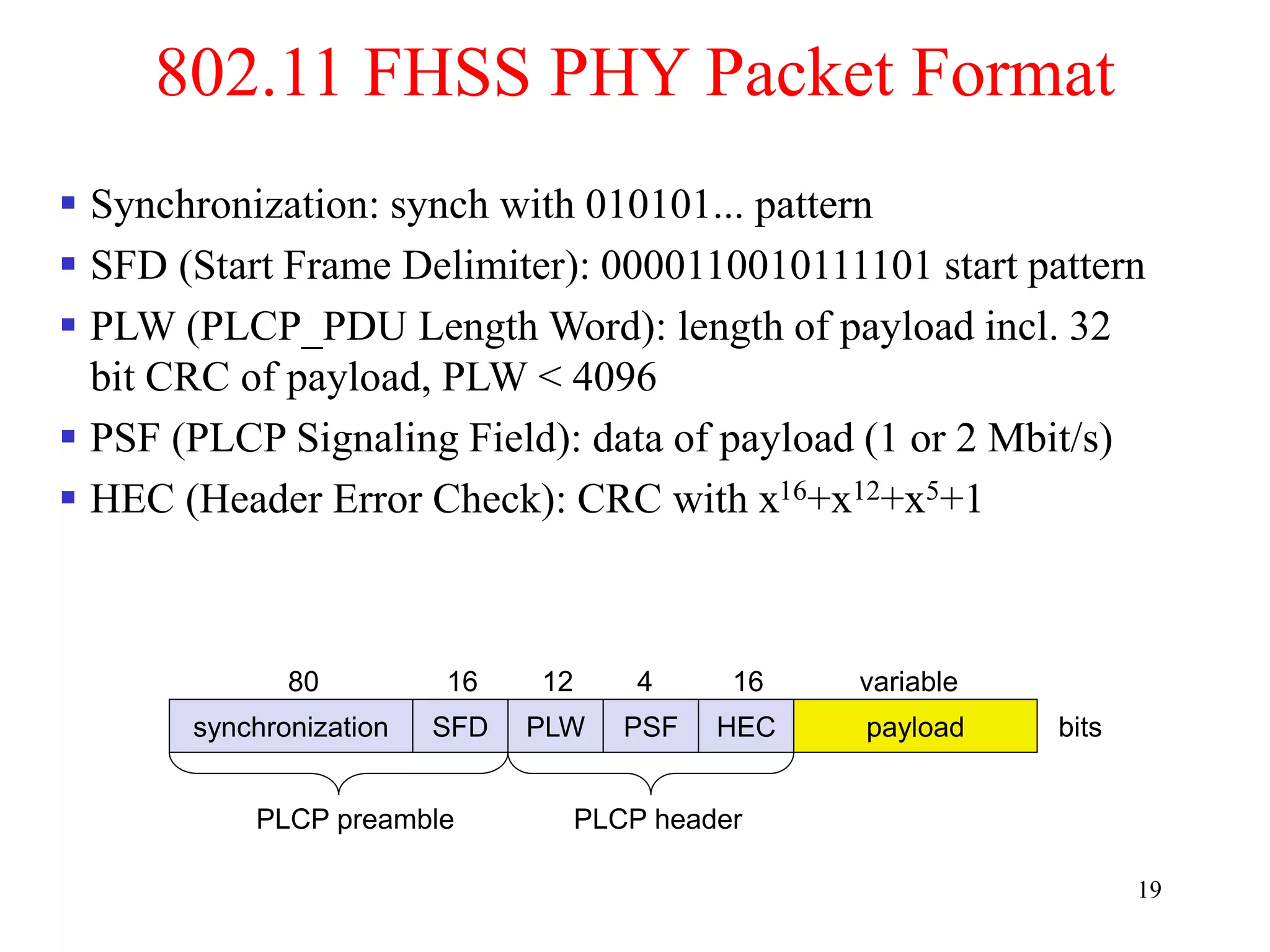
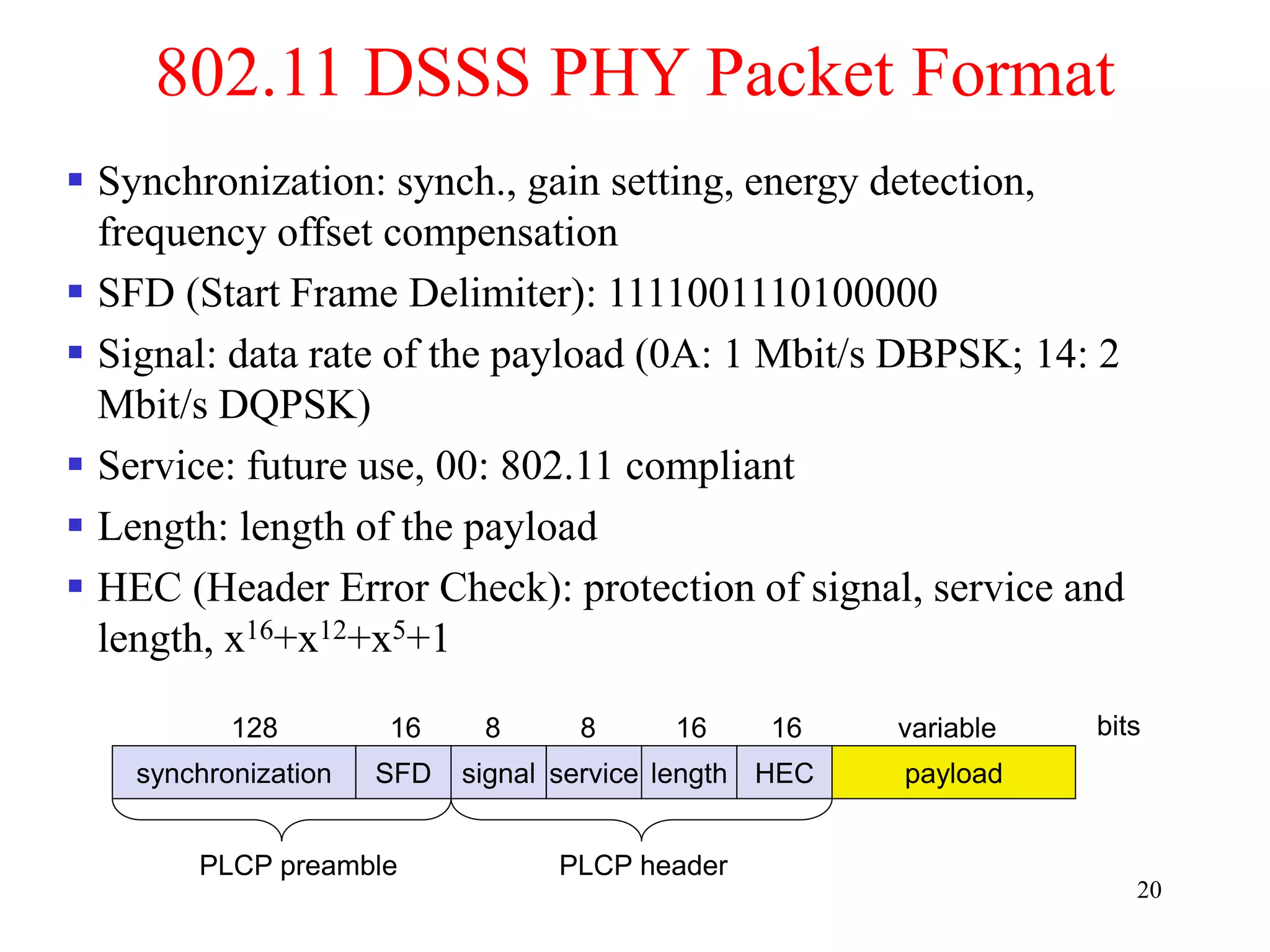
The document discusses wireless local area networks (WLANs) and personal area networks (PANs). It describes the characteristics and fundamentals of WLANs, including their advantages like flexibility and lower costs, and disadvantages such as lower bandwidth and security issues. It provides details on common wireless standards like IEEE 802.11, Bluetooth, and HomeRF. It also compares infrastructure-based and ad-hoc network topologies and summarizes key aspects of the IEEE 802.11 standard including services, physical layers, and frame formats.

![23
Operating channels for 802.11a / US U-NII
5150 [MHz]
5180 5350
5200
36 44
16.6 MHz
center frequency =
5000 + 5*channel number [MHz]
channel
40 48 52 56 60 64
149 153 157 161
5220 5240 5260 5280 5300 5320
5725 [MHz]
5745 5825
5765
16.6 MHz
channel
5785 5805](https://image.slidesharecdn.com/chapter1-230222061918-ce259a5c/75/awsn-module-1-ppt-23-2048.jpg)
![27
Channel Selection (Non-overlapping)
2400
[MHz]
2412 2483.5
2442 2472
channel 1 channel 7 channel 13
Europe (ETSI)
US (FCC)/Canada (IC)
2400
[MHz]
2412 2483.5
2437 2462
channel 1 channel 6 channel 11
22 MHz
22 MHz](https://image.slidesharecdn.com/chapter1-230222061918-ce259a5c/75/awsn-module-1-ppt-27-2048.jpg)
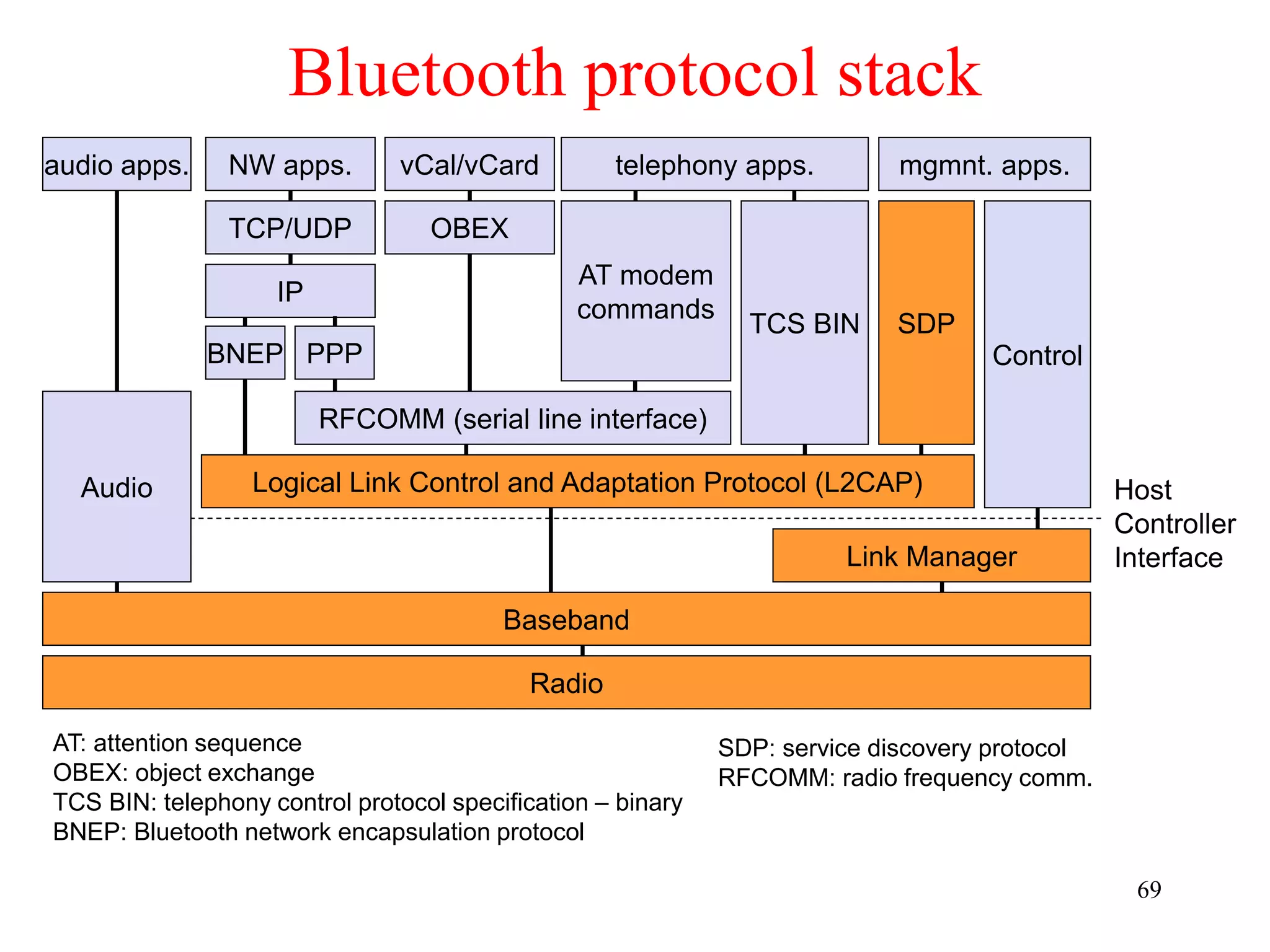
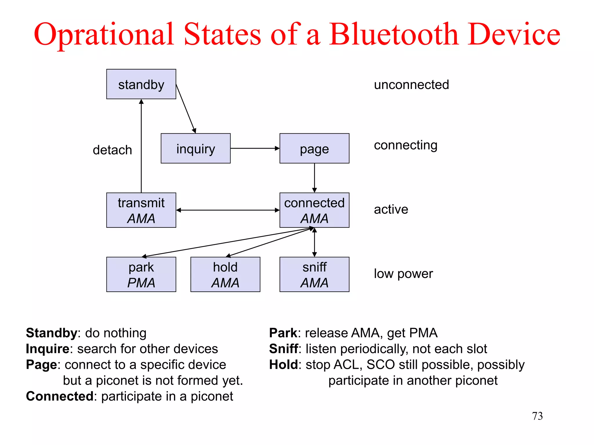
![62
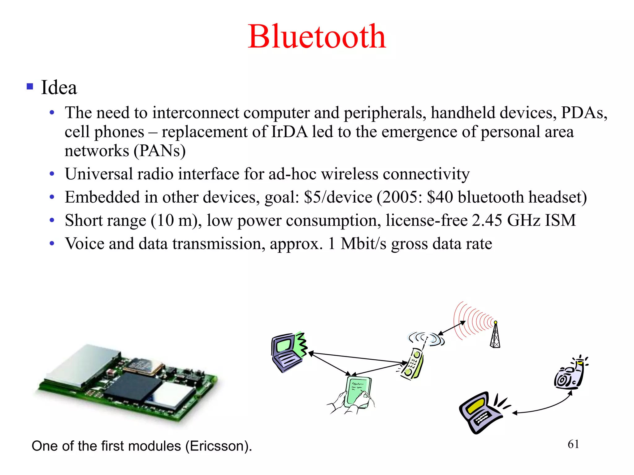
Bluetooth
History
• 1994: Ericsson (Mattison/Haartsen), “MC-link” project
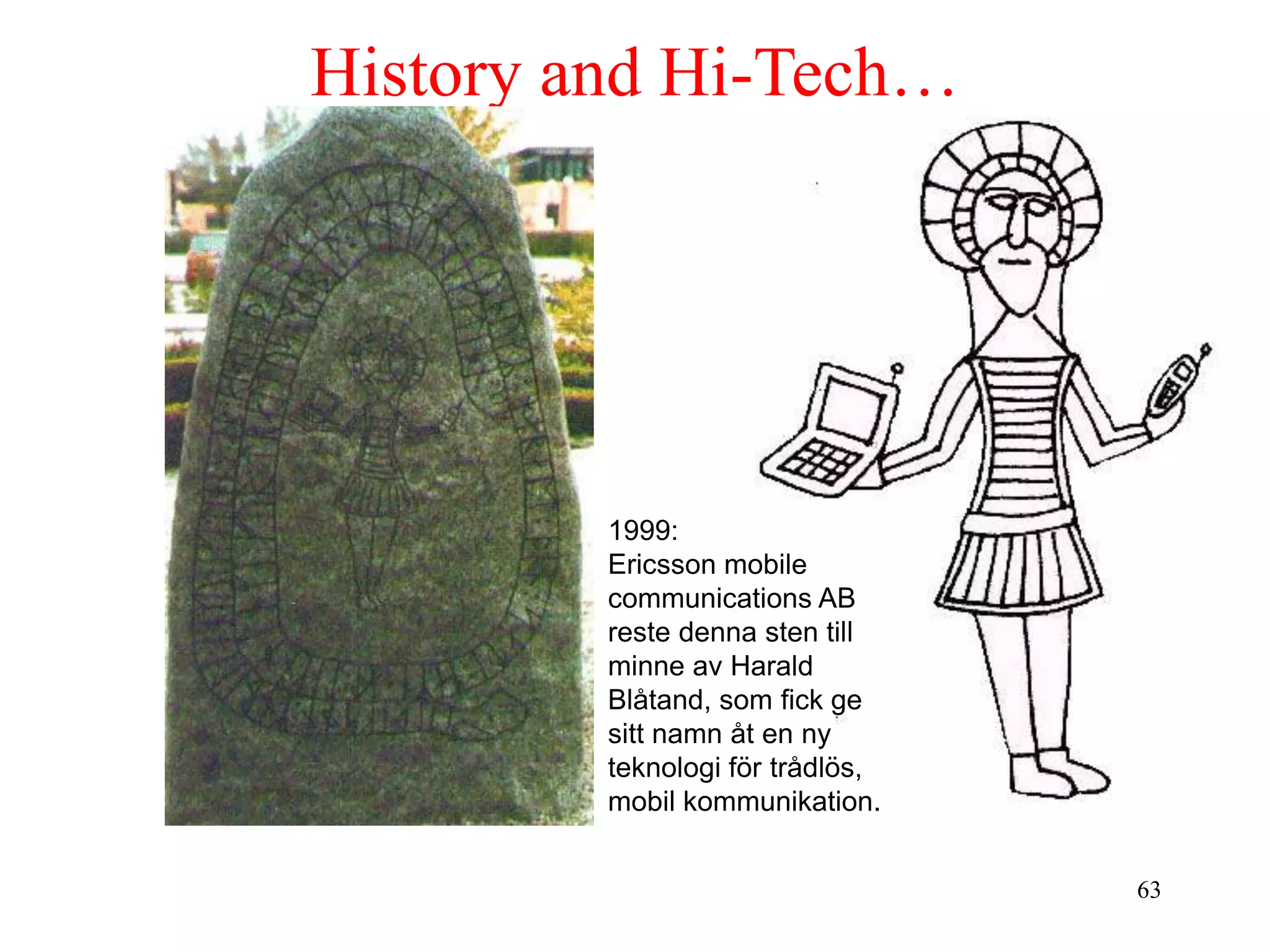
• Renaming of the project: Bluetooth according to Harald “Blåtand” Gormsen
[son of Gorm], King of Denmark in the 10th century
• 1998: foundation of Bluetooth SIG, www.bluetooth.org
• 1999: erection of a rune stone at Ercisson/Lund ;-)
• 2001: first consumer products for mass market, spec. version 1.1 released
• Nov. 8, 2004 (Overland Park, KS): Version 2.0 + EDR (Enhanced Data
Rate) is announced. Up to 3 Mbps.
Bluetooth Special Interest Group (SIG)
• Original founding members: Ericsson, Intel, IBM, Nokia, Toshiba
• Added promoters: 3Com, Agere (was: Lucent), Microsoft, Motorola
• > 2500 members
• Common specification and certification of products
IEEE founded IEEE 802.15 for Wireless Personal Area Networks
(WPAN) and approved a Bluetooth-based standard.
(was: )](https://image.slidesharecdn.com/chapter1-230222061918-ce259a5c/75/awsn-module-1-ppt-62-2048.jpg)


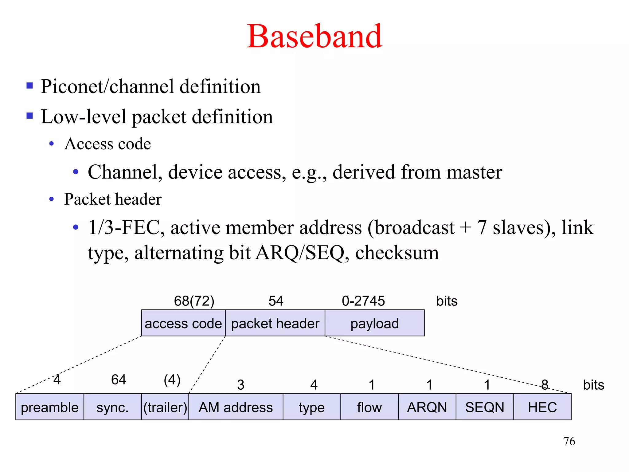
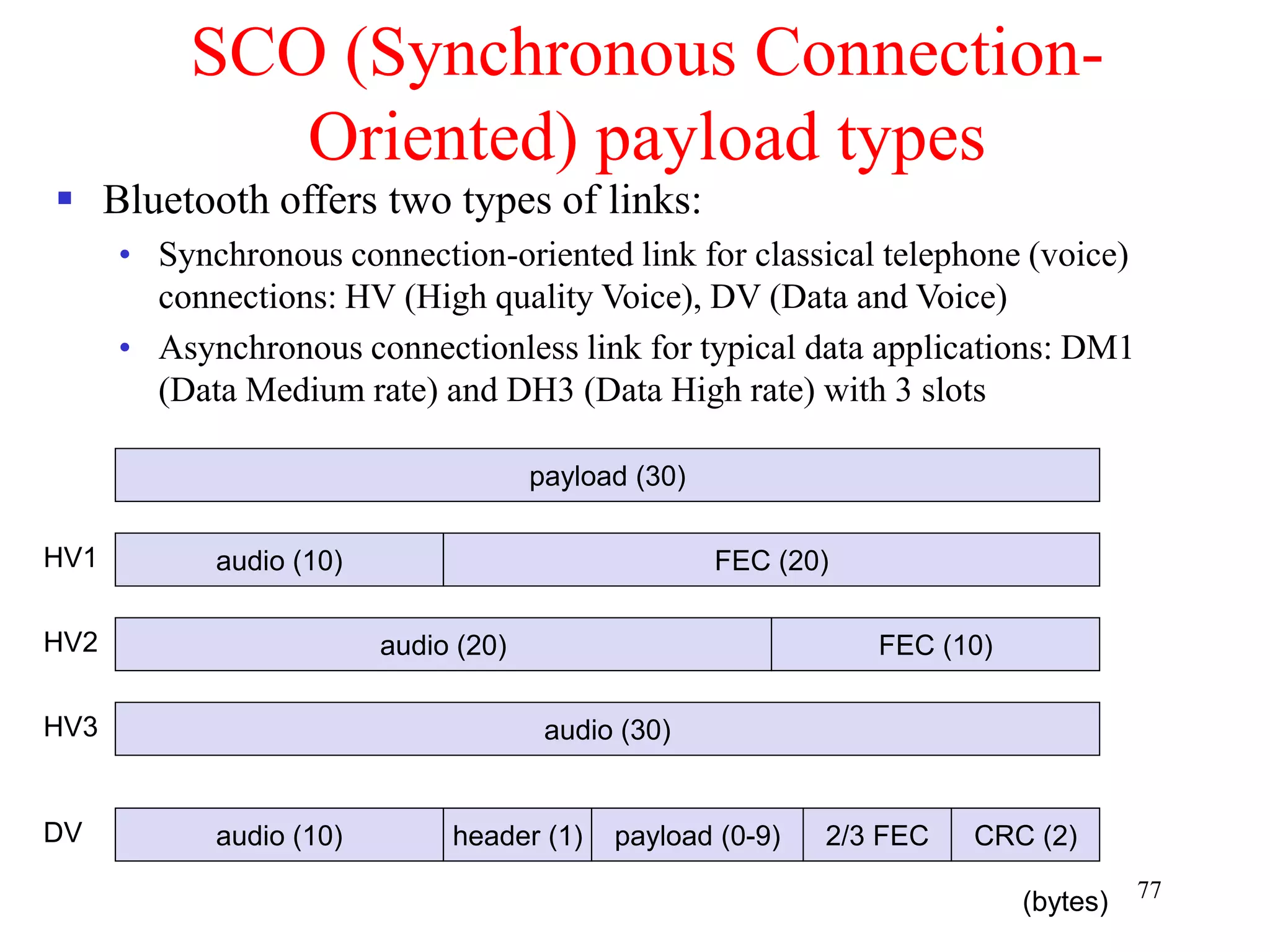
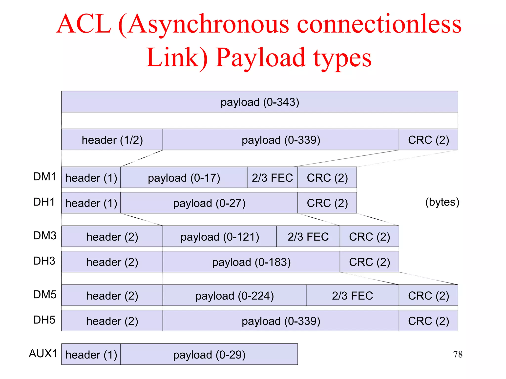
![79
Baseband data rates
Payload User Symmetric Asymmetric
Header Payload max. Rate max. Rate [kbit/s]
Type [byte] [byte] FEC CRC [kbit/s] Forward Reverse
DM1 1 0-17 2/3 yes 108.8 108.8 108.8
DH1 1 0-27 no yes 172.8 172.8 172.8
DM3 2 0-121 2/3 yes 258.1 387.2 54.4
DH3 2 0-183 no yes 390.4 585.6 86.4
DM5 2 0-224 2/3 yes 286.7 477.8 36.3
DH5 2 0-339 no yes 433.9 723.2 57.6
AUX1 1 0-29 no no 185.6 185.6 185.6
HV1 na 10 1/3 no 64.0
HV2 na 20 2/3 no 64.0
HV3 na 30 no no 64.0
DV 1 D 10+(0-9) D 2/3 D yes D 64.0+57.6 D
ACL
1 slot
3 slot
5 slot
SCO
Data Medium/High rate, High-quality Voice, Data and Voice](https://image.slidesharecdn.com/chapter1-230222061918-ce259a5c/75/awsn-module-1-ppt-79-2048.jpg)
![110
Bluetooth may act like a rogue member of the 802.11 network
• Does not know anything about gaps, inter frame spacing etc.
IEEE 802.15-2 discusses these problems
• Proposal: Adaptive Frequency Hopping
• a non-collaborative Coexistence Mechanism
Real effects? Many different opinions, publications, tests,
formulae, …
• Results from complete breakdown to almost no effect
• Bluetooth (FHSS) seems more robust than 802.11b (DSSS)
802.11 vs. 802.15/Bluetooth
t
f [MHz]
2402
2480 802.11b
3 channels
(separated by
installation)
ACK
DIFS
DIFS
SIFS 1000 byte
SIFS
DIFS
500 byte
ACK
DIFS 500 byte
SIFS
ACK
DIFS
500 byte
DIFS
100
byte
SIFS
ACK
DIFS
100
byte
SIFS
ACK
DIFS
100
byte
SIFS
ACK
DIFS
100
byte
SIFS
ACK
DIFS
100
byte
SIFS
ACK
802.15.1
79 channels
(separated by
hopping pattern)](https://image.slidesharecdn.com/chapter1-230222061918-ce259a5c/75/awsn-module-1-ppt-110-2048.jpg)