The paper presents an Improved Hierarchical Coordination for Data Gathering (HCDG) routing schema for Wireless Sensor Networks (WSNs) that effectively reduces energy consumption and minimizes delay through a multi-level chain formation method. The proposed HCDG method is analyzed and compared to existing routing methodologies—such as LEACH and PEGASIS—demonstrating better performance in large-scale deployments. Key phases of the HCDG framework include chain hierarchy formation, selection of leader and coordinator nodes, and data transmission strategies aimed at maintaining network efficiency and longevity.
![Manal, Laiali & Rizvi
International Journal of Computer Science and Security (IJCSS), Volume (5) : Issue (5) : 2011 443
Hierarchical Coordination for Data Gathering (HCDG) in Wireless
Sensor Networks
Manal AL-Bzoor manal.al-bzoor@uconn.edu
Department of Computer Science & Engineering
University of Connecticut
Storrs, CT, 06269 USA
Laiali Almazaydeh lalmazay@bridgeport.edu
Department of Computer Science
University of Bridgeport
Bridgeport, CT 06604 USA.
Syed Rizvi srizvi@ecpi.edu
Electronics Engineering Technology Department
ECPI University
Virginia Beach, VA 23462, USA.
Abstract
A wireless sensor network (WSN) consists of large number of sensor nodes where each node
operates by a finite battery for sensing, computing, and performing wireless communication tasks.
Energy aware routing and MAC protocols were proposed to prolong the lifetime of WSNs. MAC
protocols reduce energy consumption by putting the nodes into sleep mode for a relatively longer
period of time; thereby minimizing collisions and idle listening time. On the other hand, efficient
energy aware routing is achieved by finding the best path from the sensor nodes to the Base Sta-
tion (BS) where energy consumption is minimal. In almost all solutions there is always a tradeoff
between power consumption and delay reduction. This paper presents an improved hierarchical
coordination for data gathering (HCDG) routing schema for WSNs based on multi-level chains
formation with data aggregation. Also, this paper provides an analytical model for energy con-
sumption in WSN to compare the performance of our proposed HCDG schema with the near op-
timal energy reduction methodology, PEGASIS. Our results demonstrate that the proposed
routing schema provides relatively lower energy consumption with minimum delay for large scale
WSNs.
Keywords: Energy Consumption, MAC Routing Protocols, Sensor Nodes, Wireless Sensor
Network.
1. INTRODUCTION
There is a tremendous increase in the usage of wireless sensor networks (WSNs) for sensing
and monitoring applications in the natural environment, industry, and military domains [1]. These
networks usually consist of many low-power, low-energy, and low-cost sensor nodes with wireless
communication links. The sensor nodes sense data from the nearby environment, receive data
from other nodes , process the data, and send necessary data to other nodes or to the base sta-
tion (BS) [2][3]. These networks are typically deployed in an Ad hoc manner where the participat-
ing nodes in a network share the same communication medium.
The sensor nodes are usually operated by batteries and left unattended after their deployment.
This makes power saving scheme as one of the critical issues in WSNs as network should be
considered to have a certain lifetime during which nodes should have sufficient energy for gather-
ing, processing, and transmitting the information. Therefore, any protocol developed for sensor
nodes communication should be designed to be extremely energy-efficient. The design of an](https://image.slidesharecdn.com/ijcss-587-160110054429/75/Hierarchical-Coordination-for-Data-Gathering-HCDG-in-Wireless-Sensor-Networks-1-2048.jpg)
![Manal, Laiali & Rizvi
International Journal of Computer Science and Security (IJCSS), Volume (5) : Issue (5) : 2011 444
energy-efficient protocol is an imminent problem to solve in WSNs [4].
WSNs usually consist of hundreds or even thousands of sensor nodes which may be sparsely
distributed in non predefined remote locations. Thus, it becomes extremely difficult and computa-
tionally infeasible to recharge or replace the dead batteries of the network nodes. When sensor
nodes in a WSN run out of energy they stop functioning as either data originators or data routers,
causing a progressive deconstruction of the network. Therefore, one of the most stringent limita-
tions that the development of a WSN faces today is the power consumption issues. In reality, a
sensor node typically consumes the most of its energy during communication with the other
nodes. However, lower energy expenditure takes place while performing sensing and data
processing [5]. As a result, there is a great development of techniques recently requiring the eli-
mination of energy inefficiencies at all layers of the protocol stack of sensor nodes.
More precisely, research on physical and data link layers of the protocol stack has been focused
on system level energy awareness such as dynamic voltage scaling, radio communication hard-
ware, low duty cycle issues, system partitioning, and energy aware MAC protocols [6]. At the
network layer of protocol stack, the main objective is to setup the best energy-aware route from
the sensor nodes to the BS to prolong the overall network lifetime. For these reasons, while
routing protocols in traditional networks aim to accomplish a high quality of service, routing proto-
cols in WSN are more concerned towards power consumption issues.
The routing protocols developed for WSNs are classified mainly as flat routing and hierarchical or
cluster- based routing protocols [7] [8]. In the former, each node plays the same role (i.e., all ac-
tive sensor nodes collaborate with each other to perform the sensing task). In the latter approach,
however, sensor nodes are divided based on their geographical location and programmed to per-
form a different role with respect to their energy consumption. In this paper, we propose a hierar-
chical chain-based schema that introduces a new method for reducing the energy consumption.
Our proposed HCDG scheme reduces the total energy consumption and provides relatively lower
delay than the other hierarchical-based routing schemas such as LEACH [9] and PEGASIS [10].
The remainder of the paper is organized as follows: Section 2 provides an overview of the exist-
ing energy aware routing and MAC protocols for WSNs. In Section 3, we present our proposed
HCDG routing schema. Section 4 provides analytical and simulation models for the proposed me-
thod to compare the performance with the PEGASIS and LEACH schemas. Finally, Section 5
concludes the paper with future work.
2. RELATED WORK
Energy aware routing is one of the hot research areas in WSNs. In general, routing protocols for
WSNs can be classified according to their network structure as flat and hierarchical or location-
based routing protocols. Specifically, routing protocols are classified into multipath-based, query-
based, negotiation-based, quality of service (QoS)-based, and coherent-based routing protocols
[2]. In flat networks, all nodes play the same role (i.e., each participating node aggregates data). In
hierarchical protocols, nodes are divided into clusters where each cluster has one head node who
is responsible to perform data aggregation. Since only head nodes can perform data aggregation,
this reduces the energy consumption. Location-based protocols utilize position information to relay
the data to the desired regions rather than the whole network [11]. For our proposed work, we use
both hierarchical routing and location-based categories as a network structure.
Heinzelman et.al [9] introduced a hierarchical clustering algorithm for sensor networks, called Low
Energy Adaptive Cluster – based protocol (LEACH). In LEACH the operation is divided into
rounds. During each round, a set of nodes are selected as cluster–head nodes. Once selected,
these cluster-head nodes cannot become cluster heads again for the next P rounds. Thereafter,
each node has a 1/p probability of becoming a cluster head in each round. At the end of each
round, each node which is not a cluster head selects the closest cluster head and joins that cluster
to transmit data. In addition, cluster heads aggregate and compress the data and forward it to the
BS. In this algorithm, the energy consumption distributes uniformly among all nodes whereas non–](https://image.slidesharecdn.com/ijcss-587-160110054429/75/Hierarchical-Coordination-for-Data-Gathering-HCDG-in-Wireless-Sensor-Networks-2-2048.jpg)
![Manal, Laiali & Rizvi
International Journal of Computer Science and Security (IJCSS), Volume (5) : Issue (5) : 2011 445
head nodes turn off as much as possible. LEACH assumes that all nodes are in wireless transmis-
sion range of the BS which is not the case in many sensor nodes deployment algorithms. In each
round, cluster heads comprise 5% of total nodes and use TDMA as a scheduling mechanism that
makes it prone to long delays when applied to a large sensor network.
In [10] an enhancement over LEACH protocol was proposed. The protocol, called Power – Effi-
cient Gathering in Sensor Information Systems (PEGASIS) a near optimal chain-based protocol for
extending the lifetime of network. In PEGASIS, each node communicates with one of the closest
neighbors by adjusting its signal power such that it can only be heard by the closest neighbor.
Each node uses signal strength to measure the distance between its current location and the
neighboring nodes to determine the node which is at the shortest possible distance. After chain
formation, PEGASIS elects one of the nodes as a leader from the chain with respect to residual
energy usage. Unlike LEACH [9], PEGASIS [10] avoids cluster formation and uses only one node
in a chain to transmit the data to the BS rather than multiple nodes. This results in relatively lower
overhead and the bandwidth requirements from the BS.
In COSEN [12], a chain oriented sensor network for collecting information was introduced where
multiple lower chains are formulated exactly in the same manner as described in PEGASIS [10].
Each chain starts from the furthest node that includes a certain percentage of total nodes where
the number of leaders equal to the number of formulated chains. Each leader from each chain col-
lects and aggregates the data from its chain level and transmits this aggregated data to the higher
level leader until it reaches to the BS. Introducing this hierarchical chain model in COSEN alle-
viated parallel data aggregation and hence achieved higher reduction in both energy and delay
compared to PEGASIS and LEACH.
In [13], a new routing algorithm based on chaining structure was proposed. It was based on the
same idea of chain formation as suggested by PEGASIS. However, it uses different criteria for
selecting the next node in the chain formation process. PEGASIS adds the next node to the chain
as the node closer to the last node in the chain. However, this method uses the distance between
the next node and rest of the nodes that are currently part of the chain as criteria for selecting the
next node. This new method of selecting the next node ensures that the total distance from any
selected leader to other nodes in the chain is minimal and therefore offers relatively lower energy
consumption than the original PEGASIS. Simulation results [13] show that this proposed method
can reduce the total energy consumption more than the best traditional algorithms such as PEGA-
SIS and LEACH with a factor of 34%.
Our proposed routing scheme differs from the existing solutions since we combine hierarchical
chaining method for chain formation and selecting the next node based on the total distance to all
other chain members. Our proposed method lowers the burden on the chain-leader by introducing
a coordinator node who is responsible for collecting the data from the lower level chains and for-
warding it to the leader node. Our proposed scheme makes parallel data gathering more feasible
and thus provides relatively lower end-to-end delay than the other routing schemas that use the
same hierarchical structures.
3. HIERARCHICAL COORDINATION AND DATA GATHERING SCHEME
One of the main objectives of the proposed scheme is to minimize both energy consumption and
end-to-end delay which is required for data gathering in WSNs. Our proposed scheme is based on
the same assumptions as described in [9] [10] [12]. Before we present the proposed scheme, it is
worth mentioning some of our key assumptions.
1. We assume that the BS is located in a fixed place with a field of nodes deployed randomly
where all nodes are considered to be stationary.](https://image.slidesharecdn.com/ijcss-587-160110054429/75/Hierarchical-Coordination-for-Data-Gathering-HCDG-in-Wireless-Sensor-Networks-3-2048.jpg)
![Manal, Laiali & Rizvi
International Journal of Computer Science and Security (IJCSS), Volume (5) : Issue (5) : 2011 446
2. We assume that all sensor nodes encapsulate complete information about the network and
each of them is able to adjust its transmission power such that it can only be heard by its
closest neighbor.
3. We also assume that each node is capable to perform data aggregation from other nodes
with its own data into a single packet.
4. Finally, we assume that sensor nodes and BS are homogeneous and have limited energy.
Our proposed HCDG scheme differs from [12] in both chain formation strategy and in proposing
two role based coordination for each chain in the hierarchy. Our proposed schema, therefore, con-
sists of three main phases: chain hierarchy formation, coordinators and leaders groups’ selection
phase, and data transmission phase.
3.1. Chain Hierarchy Formation
In this first phase of our proposed scheme, we use the next node selection criteria proposed in
[13] and combined with [12] for hierarchical chain formation. In order to form the hierarchical
chain, we start from the furthest node from the BS as illustrated in Algorithm 1. Next, we select
the node which has the closest distance to the rest of nodes that are already exist in the chain.
The chain formation reaches to its end once a certain percentage of total number of nodes in the
field becomes members of that chain. We refer to this condition as chain saturation which
indicates that a maximum number of nodes have associated with the chain and there is no need
for extending the chain formation process. In other words, this percentage limits the number of
Start from furthest node to the BS
/*initialization phase for chain and member IDs*/
S1 CID= 0; /*chain id*/
MID=0; /*member id initialization*/
P=Percentage; /*node percentage for each chain*/
S2 Currentlocation= CID.member[MID].location
S3 while (RemainingNodeCount>0) do:
S4 while (MID < P*TotalNodeCount) do:
S5 for (i=0 to RemainingNodesCount)
S6 for (j=0 to MID);
S7 Totaldistance=Node[i].loc -CID.Member[j].loc
end for;
S8 tmpDistance = Totaldistance/MID+1;
S9 If (tmpdistance < mindistanec) then
S10 mindistance = tmpdistance;
S11 CID.member[MID+1]= node[i];
end if
S12 MID++;
S13 RemainingNodesCount--;
S14 Mindistance=Maxdistance;
end for
end while
S15 CurrentLocation=CID.member[MID].location
S16 CID++; MID=0;
end while
Algorithm 1: Chain Hierarchy Formation](https://image.slidesharecdn.com/ijcss-587-160110054429/75/Hierarchical-Coordination-for-Data-Gathering-HCDG-in-Wireless-Sensor-Networks-4-2048.jpg)
![Manal, Laiali & Rizvi
International Journal of Computer Science and Security (IJCSS), Volume (5) : Issue (5) : 2011 448
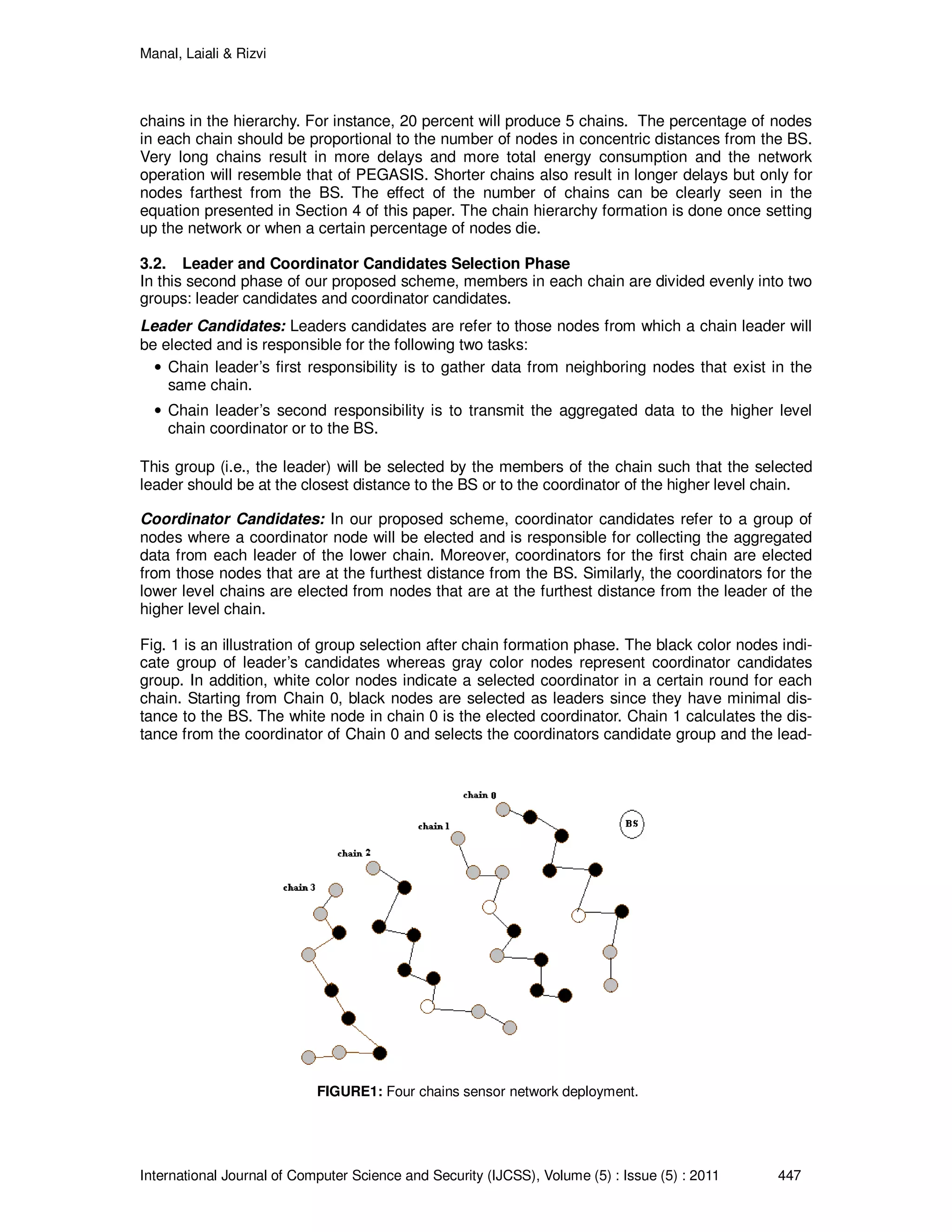
er’s candidate group. Once the group selection is made, each chain coordinator keeps acting as
a point of reference for lower chains to select candidate members for each group.
3.3. Data Transmission Phase
In this second phase of our proposed scheme, each node is assumed to have data available to be
sent to the BS in a timely basis. In addition, each chain selects one leader and one coordinator
based on the residual energy. Each sensor node will be informed by the location of the leader
node using a token which is passed by the leader of the chain to all of its neighboring nodes.
Nodes start receiving and sending the aggregated data packets in the direction of leader. Leader
of each chain collects the data and send it to the coordinator of the higher chain.
3.4. Fairness, Energy Consumption, and Delay Reduction in HCDG
Groups of coordinators and leaders nodes are selected starting from the highest level chain. For
each round, one leader and one coordinator node is selected from those groups according to the
residual energy. For the lower level chains, groups are selected after every round whenever a
new coordinator is selected in the hierarchy. As mentioned earlier, the higher level hierarchy
changes typically after every round and imposes more processing for the nodes in lower level
chains. However, this additional processing at lower level chains results in more fairness for the
higher level chain nodes which performs more processing for data aggregation and direct commu-
nication with the BS.
The next node selection criteria for each chain will ensure total minimum distance between nodes.
In the second phase, if the leader is comparatively at larger distance from the BS, it requires the
leader to adjust its transmission to maximum power in order to reach the BS and transmit the ag-
gregated data. The transmission at maximum power makes this node deplete energy faster than a
closer leader even if it starts transmitting with comparatively higher energy. The above reason
leads us to choose only those nodes as leader(s) that are closest to the BS in first chain. Similarly,
in higher level chains, we choose leaders that are closest to the coordinator node. Another addi-
tional source of energy reduction in our work comes from the fact that the data gathering
processing will be divided between the two nodes (i.e., the leader and the coordinator). The com-
bination of leader and coordinator in our proposed scheme brings a degree of parallelism since
both perform data gathering together at different levels of chain. For instance, a leader will start
gathering its data from one side of its neighbors while the coordinator in the other side is collecting
the data from the lower level. Our proposed scheme, therefore, yields comparatively lower delays
than the other hierarchical routing schema such as PEGASIS [10].
4 ANALYTICAL MODEL FOR HCDG SCHEME
Firstly, in this section we present an analytical model to approximate the energy consumption for
WSN. Secondly, we provide our critical analysis to analyze the performance of the proposed
scheme with the other well known schemes. To support our analytical model, several numerical
results will be presented in this section.
4.1. Energy Model
For the sake of analytical model, we use the same radio model as described in [10] [12] to com-
pare the performance of proposed schema with the PEGASIS [10]. This model corresponds to
the first order energy model where the parameters and values are used to evaluate the perfor-
mance of all hierarchical routing schemas in WSNs. Table 1 shows the energy parameters and
their corresponding values use for analytical model and performance evaluation. We use ElecE as
an energy consumption coefficient for the wireless transmission of a single bit whereas the para-
meter k represents the number of data bits to be transferred or received (i.e., the aggregated data
packet bits). Ampε denotes the total energy required to amplify a single bit of a transmitted signal
over the wireless medium. Finally, AggE indicates the combined amount of energy consumed for
aggregating a nodes data packet with the received data packets.](https://image.slidesharecdn.com/ijcss-587-160110054429/75/Hierarchical-Coordination-for-Data-Gathering-HCDG-in-Wireless-Sensor-Networks-6-2048.jpg)
![Manal, Laiali & Rizvi
International Journal of Computer Science and Security (IJCSS), Volume (5) : Issue (5) : 2011 449
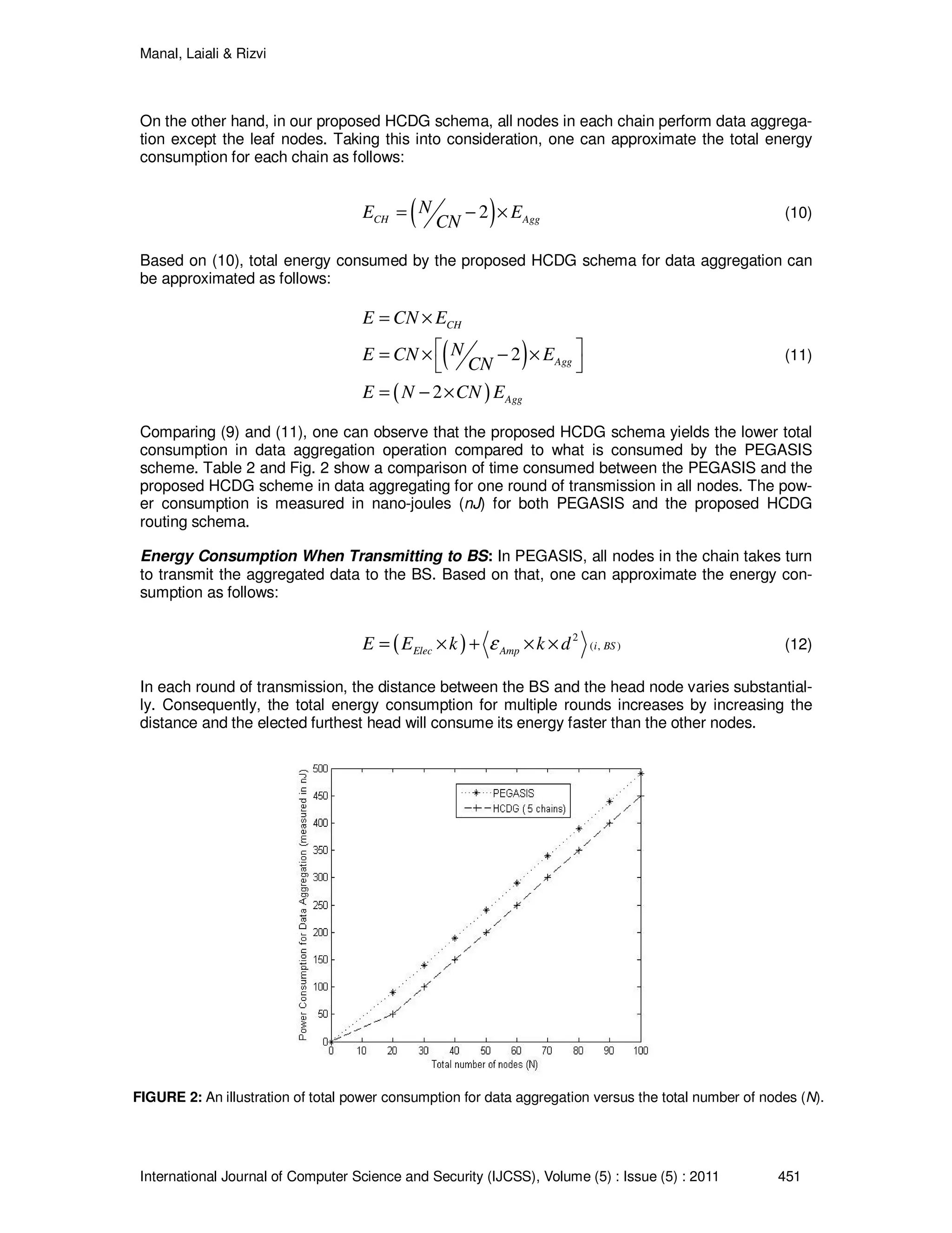
Taking the above parameters into consideration, the transmission and reception energy consump-
tion for each sensor node can be approximated as.
( ) ( ) ( )
( ) ( ) ( )
_,
2
,
,x xx
x
T T ampT k d
Elec AmpT k d
E E k E k d
E E k k dε
= +
= × + × ×
(1)
( ) ( )_
,x x ElecR R ElecE k d E k E k= ≅ × (2)
In both (1) and (2), xTE represents the total amount of energy used by a node to transmit the data
where the subscript d represents the distance between the source and the target nodes. Moreo-
ver, xRE in (1) and (2) represents the total energy consumed by a single node to receive k bits of a
data packet.
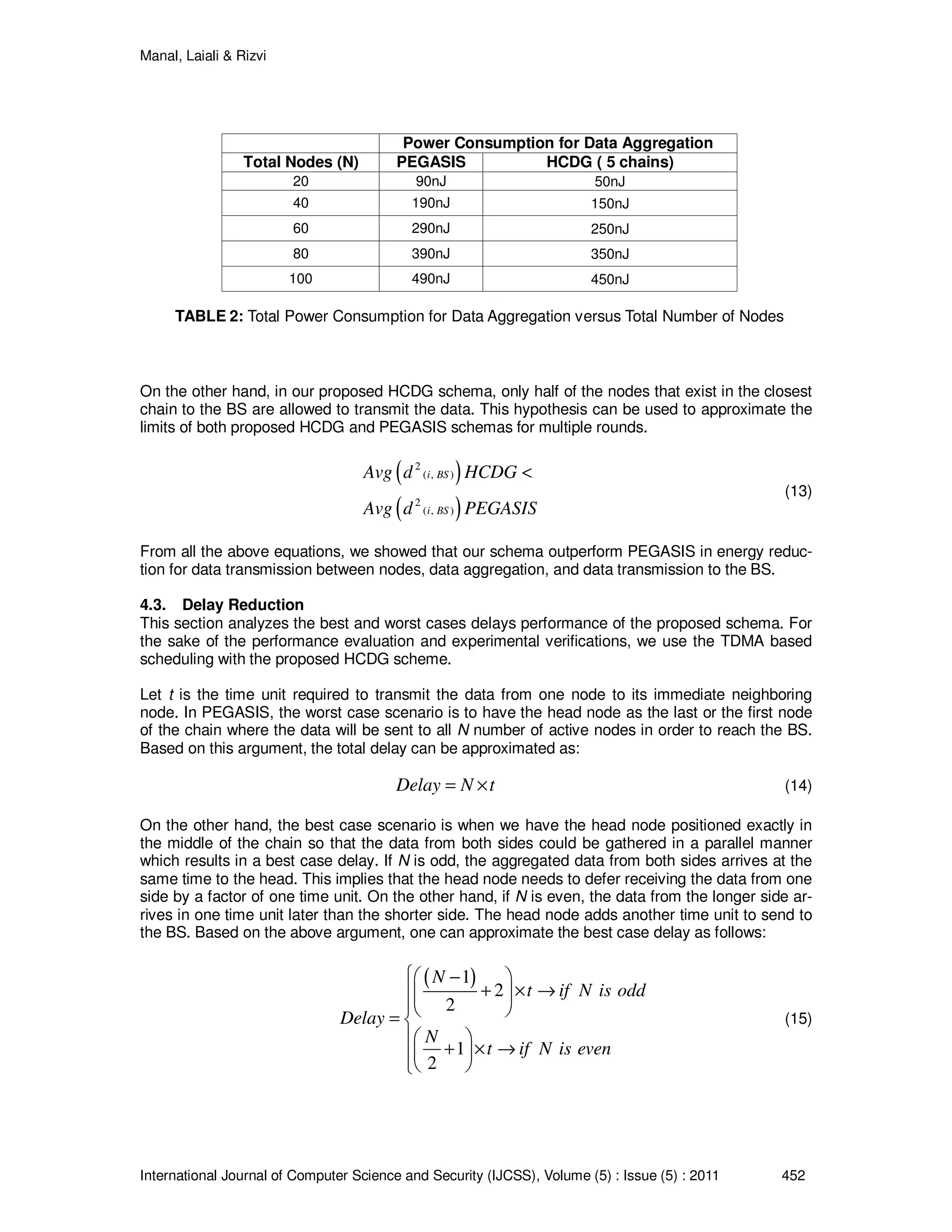
4.2. Energy Consumption Comparison
In PEGASIS [10], all nodes are arranged in one chain and only one node is selected as a head of
the chain. The head node is responsible for aggregating the data from all neighboring nodes and
transmitting it to the BS. We compare energy consumption for the three modes of operations with
N nodes in both PEGASIS and our proposed HCDG Schema.
Energy for Transmission: In PEGASIS, total energy consumption for all nodes can be approx-
imated as follows:
( ) ( )
2
1,
1
N
Elec Amp m m
m
E N E k k dε −
=
= × × + × ×
∑ (3)
In our proposed HCDG schema for N nodes with CN chains, we have n N CN= nodes per
chain. All nodes except the leader in each chain transmits the data to its closest neighboring node
with total energy equal to the total energy per chain multiplied by the number of chains. This can
be formularized as
CHE CN E= × (4)
Further elaborating (4) results
Type Parameter Value
Transmitter Electronics ElecE 50nJ
Transmitt Amplifier Ampε 100pJ/bit/ m
2
Aggregated Data Packet K 2000 bit
Aggregation Energy AggE 5nJ
TABLE 1: System Parameters Definition and Standard Values](https://image.slidesharecdn.com/ijcss-587-160110054429/75/Hierarchical-Coordination-for-Data-Gathering-HCDG-in-Wireless-Sensor-Networks-7-2048.jpg)
![Manal, Laiali & Rizvi
International Journal of Computer Science and Security (IJCSS), Volume (5) : Issue (5) : 2011 450
( ) ( ) ( )
2
1,
1
n
Elec Amp m m
m
E CN n E k k dε −
=
= × × + ×
∑ (5)
Comparing (3) with (5), we can observe that they are equal if and only if ( ),i j
d is minimal in both.
However, the selection criteria taken in our method is proved in [13] to produce smaller distances
between nodes.
Energy Consumption for Receiving Data: In PEGASIS, each node receives data if it is an in-
termediate node. Based on that, the energy consumed by each receiving node can be approx-
imated as follows:
( )1 ElecE N E k= − × × (6)
In our proposed HCDG Schema, worst scenario is the same as in PEGASIS equation (6) where
the last node in each chain is the leader for that chain and the first node in the next chain is the
coordinator of that chain which makes our schema looks like a one chain schema.
For best case scenario, when the leader and the coordinator nodes are not the last or first nodes in
the chain, the total energy consumed by each chain for receiving the data can be approximated as
follows:
( )CH Elec
N
E E k
CN
= ×
(7)
The last chain will have only 1
N
CN
− number of received packets since there is no data to be re-
ceived from lower chains. Taking this into consideration, the total energy for all chains can be ap-
proximated as:
( ) ( ) ( )
( )
( )
1 1
1
1
Elec Elec
Elec
Elec
N N
E CN E k E k
CN CN
CN N CN
E E k N
CN CN
N
E E k N
CN
= − + − ×
− −
= × +
= × −
(8)
Equation (8) is identically approximated as (6). From the above approximations, one can conclude
that the energy consumed for receiving aggregated packets is the same as it is consumed in PE-
GASIS scheme.
Energy Consumption for Data Aggregation: In PEGASIS, for the best case scenario, all nodes
perform data aggregation except the leaf nodes. Based on this, the total energy consumption can
be approximated as:
( )2 AggE N E= − × (9)](https://image.slidesharecdn.com/ijcss-587-160110054429/75/Hierarchical-Coordination-for-Data-Gathering-HCDG-in-Wireless-Sensor-Networks-8-2048.jpg)
![Manal, Laiali & Rizvi
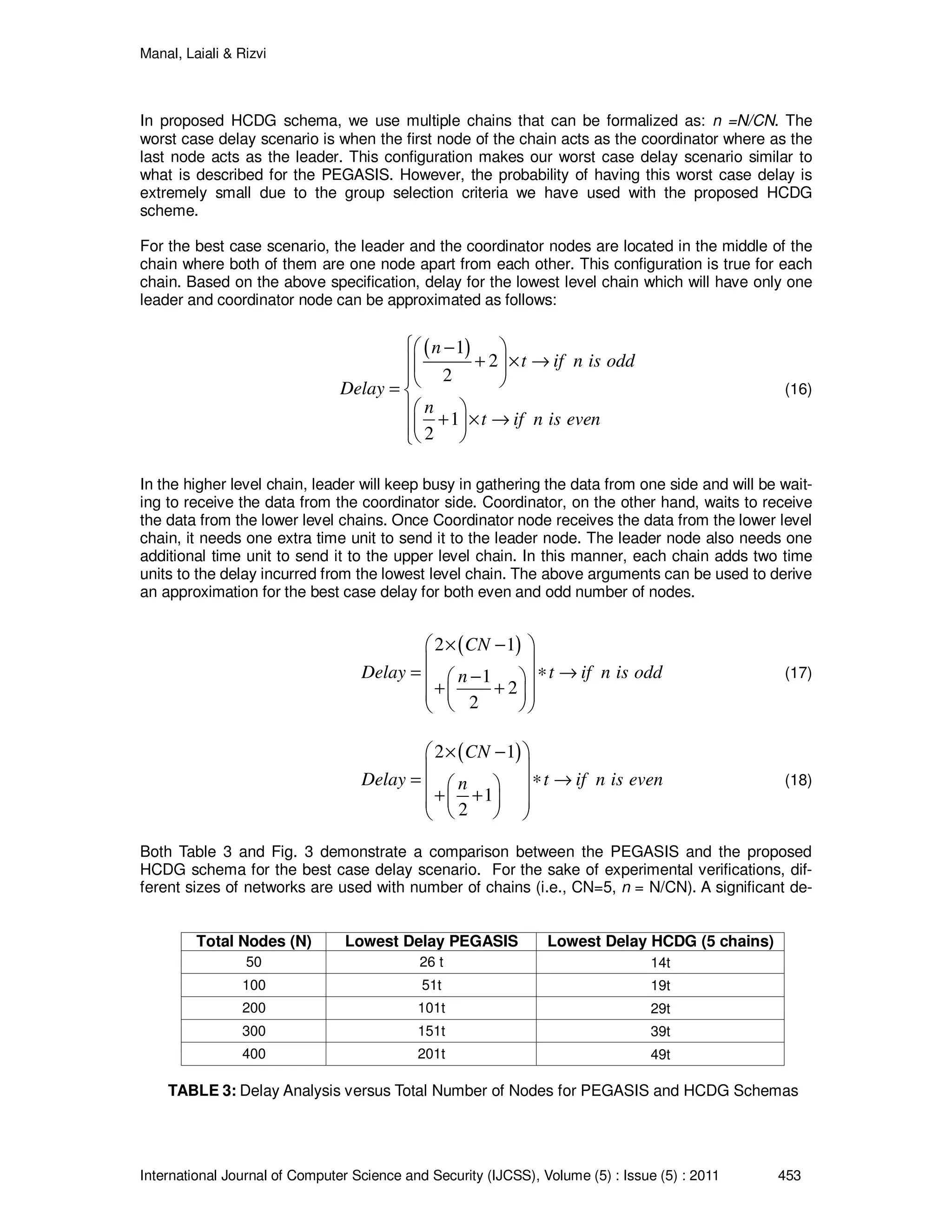
International Journal of Computer Science and Security (IJCSS), Volume (5) : Issue (5) : 2011 454
lay reduction was obtained by using our proposed HCDG schema when compare to the PEGA-
SIS for denser networks.
5. CONCLUSION
In this paper, we presented a new routing schema, hierarchical Coordination for Chain Based Da-
ta Gathering (HCDG) for WSN. The proposed HCDG schema introduced a new concept of lead-
ers and coordinators nodes in a multichain hierarchical sensor network. In order to support the
proposed HCDG schema, this paper provided a complete analytical model to approximate the
energy consumption for wireless sensor nodes. Our numerical results demonstrate that the pro-
posed HCDG schema can reduce energy consumption by a large magnitude when compared to
the PEGASIS which was originally designed to outperform the well known LEACH method. Also,
the analytical model and the results showed that the proposed HCDG schema substantially re-
duces the delay when compared to delay incurred in PEGASIS for denser WSN.
However, the numerical data which we have collected based on the proposed analytical model
gives only a clue of the actual performance of the proposed HCDG schema. This is mainly due to
the fact that the random generation of the wireless sensor nodes is hard to model using the ma-
thematical equations presented in this paper. In future, we plan to design and conduct larger-
scale experiments and simulation for better understanding of the energy consumption of the pro-
posed HCDG schema and their correlations with different chain formation criteria and other de-
sign alternatives for selecting leaders and coordinators nodes.
6. REFERENCES
[1] D. Estrin, R. Govindan, J. Heidemann, and S. Kumar, “Next century challenges: scalable
coordination in sensor networks,” MobiCOM, pp. 263-270, August 1999.
[2] A. Rai, S. Ale, S. Rizvi, and A. Riasat, “A new methodology for self localization in wireless
sensor networks,” Proc of the 12th
IEEE International Multitopic Conference, pp. 260 – 265,
December 2008.
FIGURE 3: An illustration of delay performance versus the total number of nodes (N). The delay is meas-
ured in seconds for both PEGASIS and the proposed HCDG routing schema. A significant performance
gain can be evidenced for the proposed HCDG scheme](https://image.slidesharecdn.com/ijcss-587-160110054429/75/Hierarchical-Coordination-for-Data-Gathering-HCDG-in-Wireless-Sensor-Networks-12-2048.jpg)
![Manal, Laiali & Rizvi
International Journal of Computer Science and Security (IJCSS), Volume (5) : Issue (5) : 2011 455
[3] A. Mainwaring, J. Polastre, R. Szewczyk, D. Culler, and J. Anderson,“Wireless sensor
networks for habitat monitoring,” Proc of WSNA, pp. 122-131, September 2002.
[4] C. Li, “Overview of wireless Sensor Networks,” Journal of Computer Research and
Development, vol. 42, no. 1, pp. 163-174, 2005.
[5] S. Rizvi and A. Riasat, "Use of self-adaptive methodology in wireless sensor networks for
reducing energy consumption," Proc of IEEE International Conference on Information and
Emerging Technologies, pp. 1 - 7, July 2007.
[6] K. Akkaya and M. Younis, “A Survey of Routing Protocols in Wireless Sensor Networks,”
Elsevier Ad Hoc Network Journal, vol. 3, no. 3, pp. 325-349, 2005.
[7] J. Al-Karaki and A. Kamal, “Routing techniques in wireless sensor networks: a survey,”
IEEE Wireless Communications, vol. 11, no. 6, pp.6-28, December 2004.
[8] M. Younis, M. Youssef, and K. Arisha, “Energy-aware routing in cluster-based sensor
networks”, Proc of the 10
th
IEEE/ACM(MASCOTS2002), Fort Worth, TX, October 2002.
[9] W. Heinzelman, A. Chandrakasan, and H. Balakrishnan, “Energy-efficient communication
protocols for wireless microsensor networks”, Proc of the 33
rd
Hawaii International
Conference on System Sciences, January 2000.
[10] S. Lindsay and C. Raghavendra, “PEGASIS: Power-efficient gathering in sensor
information systems”, Proc. Of the IEEE, vol. 32, no. 4, pp. 66 - 71, 2003.
[11] B. Sarazin and S. Rizvi, “A Self-Deployment Obstacle Avoidance (SOA) Algorithm for
Mobile Sensor Networks,” International Journal of Computer Science and Security (IJCSS),
Vol. 4, Issue. 3, pp. 316 - 330, 2010.
[12] N. Tabassum, Q. Mamun, and Y. Urano, “COSEN: A chain oriented sensor network for
efficient data collection,” Proc of the 3
rd
International Conference on Information
Technology: New Generations (ITNG'06), pp. 7695-2497, April 2006.
[13] K. Khamforoosh and H. Khamforoush, “A new rounting algorithm for energy reduction in
wireless sensor networks,” Proc of 2
nd
IEEE International Conference on Computer Science
and Information Technology, pp.505-509, 2009.](https://image.slidesharecdn.com/ijcss-587-160110054429/75/Hierarchical-Coordination-for-Data-Gathering-HCDG-in-Wireless-Sensor-Networks-13-2048.jpg)