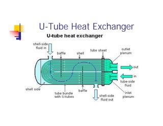
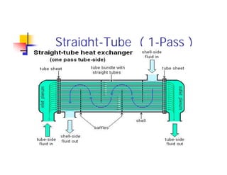
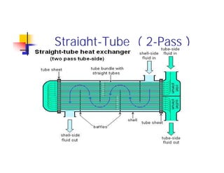
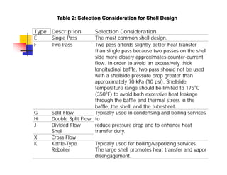
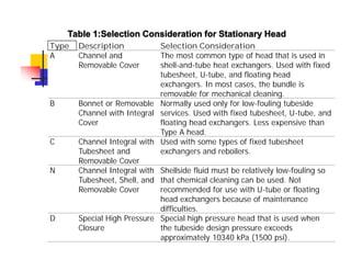
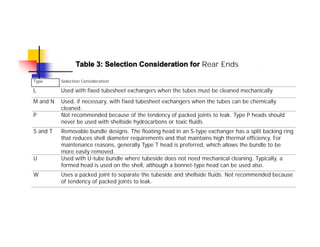
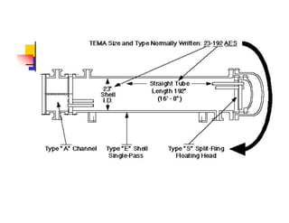
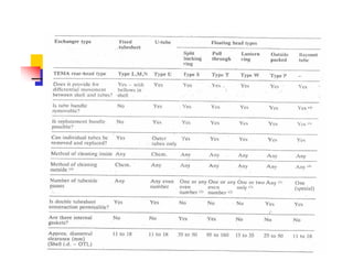
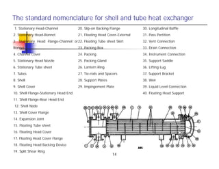
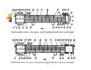
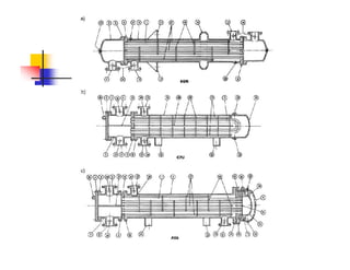
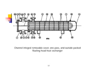
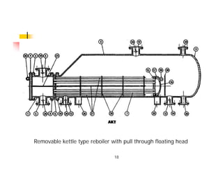
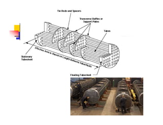
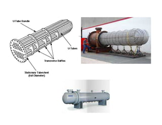
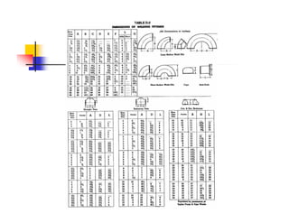
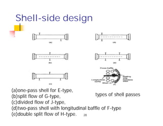
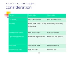
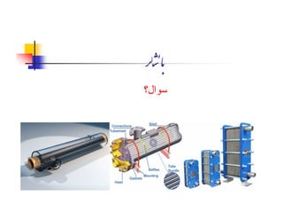
‫دوم‬‫ﻞ‬
:
‫ای‬ ‫ﻮ‬‫ﻪ‬ ‫ﻮ‬‫ارﯽ‬ ‫ﺎی‬‫ﮫ‬‫ﺒﺪ‬
Shell&TubeHeatExchangers
‫ﯿﮏ‬‫ﺎ‬‫ﮑ‬‫ﻣ‬‫ﯽ‬ ‫ﻨﺪ‬ ‫ه‬ ‫دا‬
U-Tube Heat Exchanger
Straight-Tube ( 1-Pass )
Straight-Tube ( 2-Pass )
TEMA Heat Exchanger
Tubular Exchanger Manufacture’s Association(TEMA) is the most
widely used ‘standard’ or ‘stipulated’ heat exchanger ‘design
code’.This is a US code and is used together with ASME Section
VIII(for the design of unfired pressure vessels).The TEMA code
specifies the mechanical design procedure, tolerances allowed and
the dimensions of the various parts of an exchanger.
TEMA Standard:
TEMA terminology
 Letters given for the front end, shell and rear end
types
 Exchanger given three letter designation
 Above is AEL
 Above letters are followed by the size of exchanger in
the form of “D-L” where D is the shell diameter and
L is the length of tubes
Shell
Front end
stationary head
type
Rear end
head
type
Heat exchanger
nomenclatures
8
Type Description Selection Consideration
E Single Pass The most common shell design.
F Two Pass Two pass affords slightly better heat transfer
than single pass because two passes on the shell
side more closely approximates counter-current
flow. In order to avoid an excessively thick
longitudinal baffle, two pass should not be used
with a shellside pressure drop greater than
approximately 70 kPa (10 psi). Shellside
temperature range should be limited to 175°C
(350°F) to avoid both excessive heat leakage
through the baffle and thermal stress in the
baffle, the shell, and the tubesheet.
G Split Flow Typically used in condensing and boiling services
to
reduce pressure drop and to enhance heat
transfer duty.
H Double Split Flow
J Divided Flow
Shell
X Cross Flow
K Kettle-Type
Reboiler
Typically used for boiling/vaporizing services.
The large shell promotes heat transfer and vapor
disengagement.
Table 2: Selection Consideration for Shell Design
Type Description Selection Consideration
A Channel and
Removable Cover
The most common type of head that is used in
shell-and-tube heat exchangers. Used with fixed
tubesheet, U-tube, and floating head
exchangers. In most cases, the bundle is
removable for mechanical cleaning.
B Bonnet or Removable
Channel with Integral
Cover
Normally used only for low-fouling tubeside
services. Used with fixed tubesheet, U-tube, and
floating head exchangers. Less expensive than
Type A head.
C Channel Integral with
Tubesheet and
Removable Cover
Used with some types of fixed tubesheet
exchangers and reboilers.
N Channel Integral with
Tubesheet, Shell, and
Removable Cover
Shellside fluid must be relatively low-fouling so
that chemical cleaning can be used. Not
recommended for use with U-tube or floating
head exchangers because of maintenance
difficulties.
D Special High Pressure
Closure
Special high pressure head that is used when
the tubeside design pressure exceeds
approximately 10340 kPa (1500 psi).
Table 1:Selection Consideration for Stationary Head
Table 3: Selection Consideration for Rear Ends
Type Selection Consideration
L Used with fixed tubesheet exchangers when the tubes must be cleaned mechanically.
M and N Used, if necessary, with fixed tubesheet exchangers when the tubes can be chemically
cleaned.
P Not recommended because of the tendency of packed joints to leak. Type P heads should
never be used with shellside hydrocarbons or toxic fluids.
S and T Removable bundle designs. The floating head in an S-type exchanger has a split backing ring
that reduces shell diameter requirements and that maintains high thermal efficiency. For
maintenance reasons, generally Type T head is preferred, which allows the bundle to be
more easily removed.
U Used with U-tube bundle where tubeside does not need mechanical cleaning. Typically, a
formed head is used on the shell, although a bonnet-type head can be used also.
W Uses a packed joint to separate the tubeside and shellside fluids. Not recommended because
of tendency of packed joints to leak.
The standard nomenclature for shell and tube heat exchanger
1. Stationary Head-Channel
2. Stationary Head-Bonnet
3. Stationary Head Flange-Channel or
Bonnet
4. Channel Cover
5. Stationary Head Nozzle
6. Stationary Tube sheet
7. Tubes
8. Shell
9. Shell Cover
10. Shell Flange-Stationary Head End
11. Shell Flange-Rear Head End
12. Shell Node
13. Shell Cover Flange
14. Expansion Joint
15. Floating Tube sheet
16. Floating Head Cover
17. Floating Head Cover Flange
18. Floating Head Backing Device
19. Split Shear Ring
20. Slip-on Backing Flange
21. Floating Head Cover-External
22. Floating Tube sheet Skirt
23. Packing Box
24. Packing
25. Packing Gland
26. Lantern Ring
27. Tie-rods and Spacers
28. Support Plates
29. Impingement Plate
30. Longitudinal Baffle
31. Pass Partition
32. Vent Connection
33. Drain Connection
34. Instrument Connection
35. Support Saddle
36. Lifting Lug
37. Support Bracket
38. Weir
39. Liquid Level Connection
40. Floating Head Support
14
Removable cover, one pass, and floating head heat exchanger
Removable cover, one pass, and outside packed floating head heat exchanger
15
Channel integral removable cover, one pass, and outside packed
floating head heat exchanger
17
Removable kettle type reboiler with pull through floating head
18
21
Tube sizing: Birmingham Wire Gage
Tube-side design
Arrangement of tubes inside the heat exchanger
22
Tube-side design
Arrangement of tubes inside the heat exchanger
23
Shell-side design
types of shell passes
(a)one-pass shell for E-type,
(b)split flow of G-type,
(c)divided flow of J-type,
(d)two-pass shell with longitudinal baffle of F-type
(e)double split flow of H-type. 28
Shell-side design
1- Shell thickness is calculated based on ASME code Section VIII Div. 1 or 2
2-Minimum shell thickness for different diameters and material of constructions
Was given in TEMA standard.
29
Baffle types:
1) Segmental Baffles
30
Baffle types:
2) Rod Baffles
32
Baffle types:
3) Longitudinal vs. segmental Baffles
Baffle thickness
Baffle thickness (cont.)
Pass Partition Plate
Baffle clearances
Baffle Spacing
Tie rods and spacers
Tie rods and spacers (Cont.)
Tie rods and spacers (sizes)
Gaskets:
Actual Tubesheet thickness should be calculated using
ASME code Section VIII and/or TEMA calculation
procedures (Paragraph A.13)
Tubesheet
Tubesheet (cont.)
Tubesheet (cont.): Tube hole tolerances
Tubesheet (cont.): Tube hole ligament
Tubesheet (cont.): tube to tubesheet joint
Flexible joint (expansion joint)
General design
consideration
Factor Tube-side Shell-side
Corrosion More corrosive fluid Less corrosive fluids
Fouling Fluids with high fouling
and scaling
Low fouling and scaling
Fluid temperature High temperature Low temperature
Operating pressure Fluids with high pressure Fluids with low pressure
Viscosity Less viscous fluid More viscous fluid
Stream flow rate High flow rate Low flow rate
54
‫ﺸ‬‫ﺎ‬‫ﺑ‬
‫ﺳﻮال؟‬

Chapter 2-Shell & Tube Heat Exchangers.pdf

  • 1.
    ‫دوم‬‫ﻞ‬ : ‫ای‬ ‫ﻮ‬‫ﻪ‬ ‫ﻮ‬‫ارﯽ‬‫ﺎی‬‫ﮫ‬‫ﺒﺪ‬ Shell&TubeHeatExchangers ‫ﯿﮏ‬‫ﺎ‬‫ﮑ‬‫ﻣ‬‫ﯽ‬ ‫ﻨﺪ‬ ‫ه‬ ‫دا‬
  • 2.
  • 3.
  • 4.
  • 5.
    TEMA Heat Exchanger TubularExchanger Manufacture’s Association(TEMA) is the most widely used ‘standard’ or ‘stipulated’ heat exchanger ‘design code’.This is a US code and is used together with ASME Section VIII(for the design of unfired pressure vessels).The TEMA code specifies the mechanical design procedure, tolerances allowed and the dimensions of the various parts of an exchanger.
  • 6.
  • 7.
    TEMA terminology  Lettersgiven for the front end, shell and rear end types  Exchanger given three letter designation  Above is AEL  Above letters are followed by the size of exchanger in the form of “D-L” where D is the shell diameter and L is the length of tubes Shell Front end stationary head type Rear end head type
  • 8.
  • 9.
    Type Description SelectionConsideration E Single Pass The most common shell design. F Two Pass Two pass affords slightly better heat transfer than single pass because two passes on the shell side more closely approximates counter-current flow. In order to avoid an excessively thick longitudinal baffle, two pass should not be used with a shellside pressure drop greater than approximately 70 kPa (10 psi). Shellside temperature range should be limited to 175°C (350°F) to avoid both excessive heat leakage through the baffle and thermal stress in the baffle, the shell, and the tubesheet. G Split Flow Typically used in condensing and boiling services to reduce pressure drop and to enhance heat transfer duty. H Double Split Flow J Divided Flow Shell X Cross Flow K Kettle-Type Reboiler Typically used for boiling/vaporizing services. The large shell promotes heat transfer and vapor disengagement. Table 2: Selection Consideration for Shell Design
  • 10.
    Type Description SelectionConsideration A Channel and Removable Cover The most common type of head that is used in shell-and-tube heat exchangers. Used with fixed tubesheet, U-tube, and floating head exchangers. In most cases, the bundle is removable for mechanical cleaning. B Bonnet or Removable Channel with Integral Cover Normally used only for low-fouling tubeside services. Used with fixed tubesheet, U-tube, and floating head exchangers. Less expensive than Type A head. C Channel Integral with Tubesheet and Removable Cover Used with some types of fixed tubesheet exchangers and reboilers. N Channel Integral with Tubesheet, Shell, and Removable Cover Shellside fluid must be relatively low-fouling so that chemical cleaning can be used. Not recommended for use with U-tube or floating head exchangers because of maintenance difficulties. D Special High Pressure Closure Special high pressure head that is used when the tubeside design pressure exceeds approximately 10340 kPa (1500 psi). Table 1:Selection Consideration for Stationary Head
  • 11.
    Table 3: SelectionConsideration for Rear Ends Type Selection Consideration L Used with fixed tubesheet exchangers when the tubes must be cleaned mechanically. M and N Used, if necessary, with fixed tubesheet exchangers when the tubes can be chemically cleaned. P Not recommended because of the tendency of packed joints to leak. Type P heads should never be used with shellside hydrocarbons or toxic fluids. S and T Removable bundle designs. The floating head in an S-type exchanger has a split backing ring that reduces shell diameter requirements and that maintains high thermal efficiency. For maintenance reasons, generally Type T head is preferred, which allows the bundle to be more easily removed. U Used with U-tube bundle where tubeside does not need mechanical cleaning. Typically, a formed head is used on the shell, although a bonnet-type head can be used also. W Uses a packed joint to separate the tubeside and shellside fluids. Not recommended because of tendency of packed joints to leak.
  • 14.
    The standard nomenclaturefor shell and tube heat exchanger 1. Stationary Head-Channel 2. Stationary Head-Bonnet 3. Stationary Head Flange-Channel or Bonnet 4. Channel Cover 5. Stationary Head Nozzle 6. Stationary Tube sheet 7. Tubes 8. Shell 9. Shell Cover 10. Shell Flange-Stationary Head End 11. Shell Flange-Rear Head End 12. Shell Node 13. Shell Cover Flange 14. Expansion Joint 15. Floating Tube sheet 16. Floating Head Cover 17. Floating Head Cover Flange 18. Floating Head Backing Device 19. Split Shear Ring 20. Slip-on Backing Flange 21. Floating Head Cover-External 22. Floating Tube sheet Skirt 23. Packing Box 24. Packing 25. Packing Gland 26. Lantern Ring 27. Tie-rods and Spacers 28. Support Plates 29. Impingement Plate 30. Longitudinal Baffle 31. Pass Partition 32. Vent Connection 33. Drain Connection 34. Instrument Connection 35. Support Saddle 36. Lifting Lug 37. Support Bracket 38. Weir 39. Liquid Level Connection 40. Floating Head Support 14
  • 15.
    Removable cover, onepass, and floating head heat exchanger Removable cover, one pass, and outside packed floating head heat exchanger 15
  • 17.
    Channel integral removablecover, one pass, and outside packed floating head heat exchanger 17
  • 18.
    Removable kettle typereboiler with pull through floating head 18
  • 21.
  • 22.
    Tube-side design Arrangement oftubes inside the heat exchanger 22
  • 23.
    Tube-side design Arrangement oftubes inside the heat exchanger 23
  • 28.
    Shell-side design types ofshell passes (a)one-pass shell for E-type, (b)split flow of G-type, (c)divided flow of J-type, (d)two-pass shell with longitudinal baffle of F-type (e)double split flow of H-type. 28
  • 29.
    Shell-side design 1- Shellthickness is calculated based on ASME code Section VIII Div. 1 or 2 2-Minimum shell thickness for different diameters and material of constructions Was given in TEMA standard. 29
  • 30.
  • 31.
  • 32.
    32 Baffle types: 3) Longitudinalvs. segmental Baffles
  • 33.
  • 34.
  • 35.
  • 36.
  • 37.
  • 39.
    Tie rods andspacers
  • 40.
    Tie rods andspacers (Cont.)
  • 41.
    Tie rods andspacers (sizes)
  • 42.
  • 43.
    Actual Tubesheet thicknessshould be calculated using ASME code Section VIII and/or TEMA calculation procedures (Paragraph A.13) Tubesheet
  • 44.
  • 45.
    Tubesheet (cont.): Tubehole tolerances
  • 46.
  • 47.
    Tubesheet (cont.): tubeto tubesheet joint
  • 48.
    Tubesheet (cont.): tubeto tubesheet joint
  • 49.
    Tubesheet (cont.): tubeto tubesheet joint
  • 50.
    Tubesheet (cont.): tubeto tubesheet joint
  • 51.
  • 54.
    General design consideration Factor Tube-sideShell-side Corrosion More corrosive fluid Less corrosive fluids Fouling Fluids with high fouling and scaling Low fouling and scaling Fluid temperature High temperature Low temperature Operating pressure Fluids with high pressure Fluids with low pressure Viscosity Less viscous fluid More viscous fluid Stream flow rate High flow rate Low flow rate 54
  • 55.