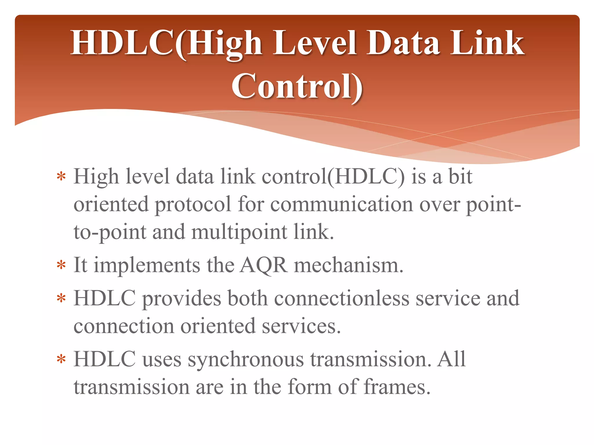
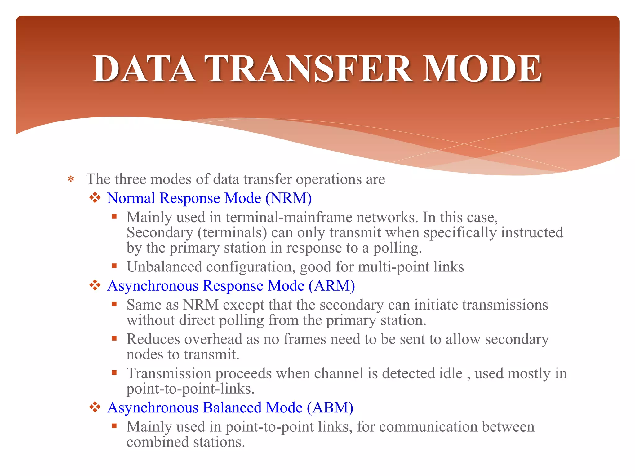
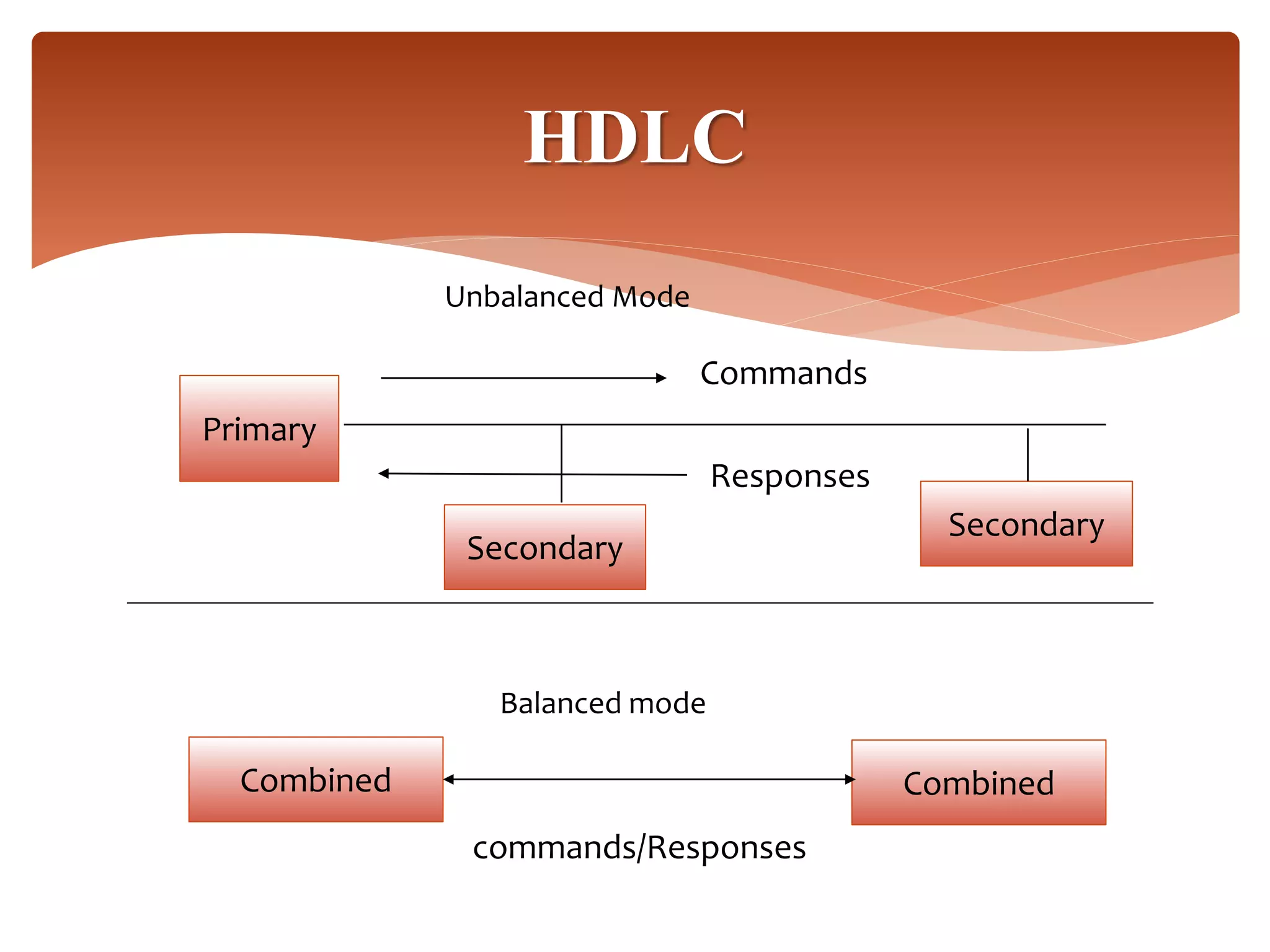
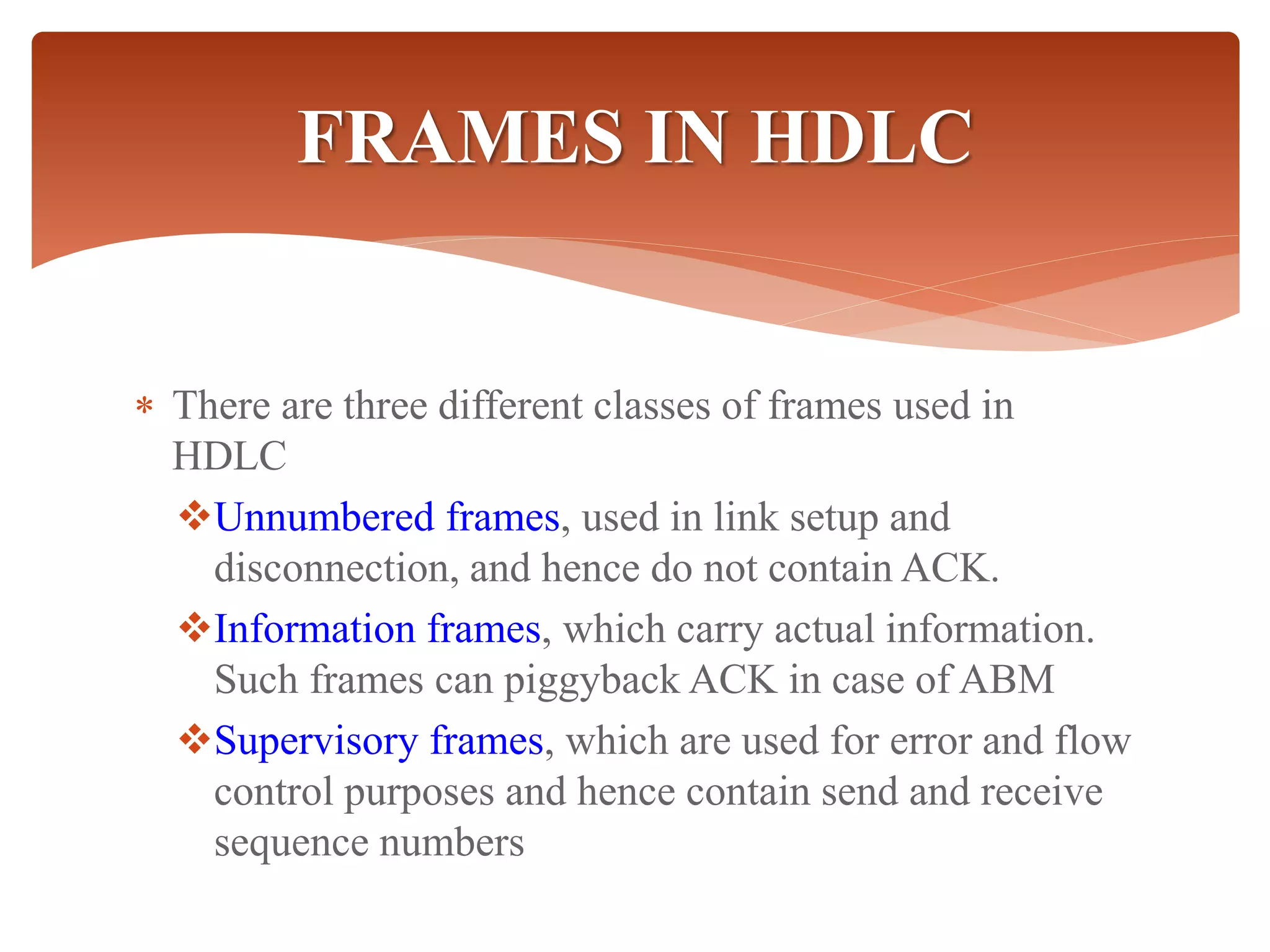
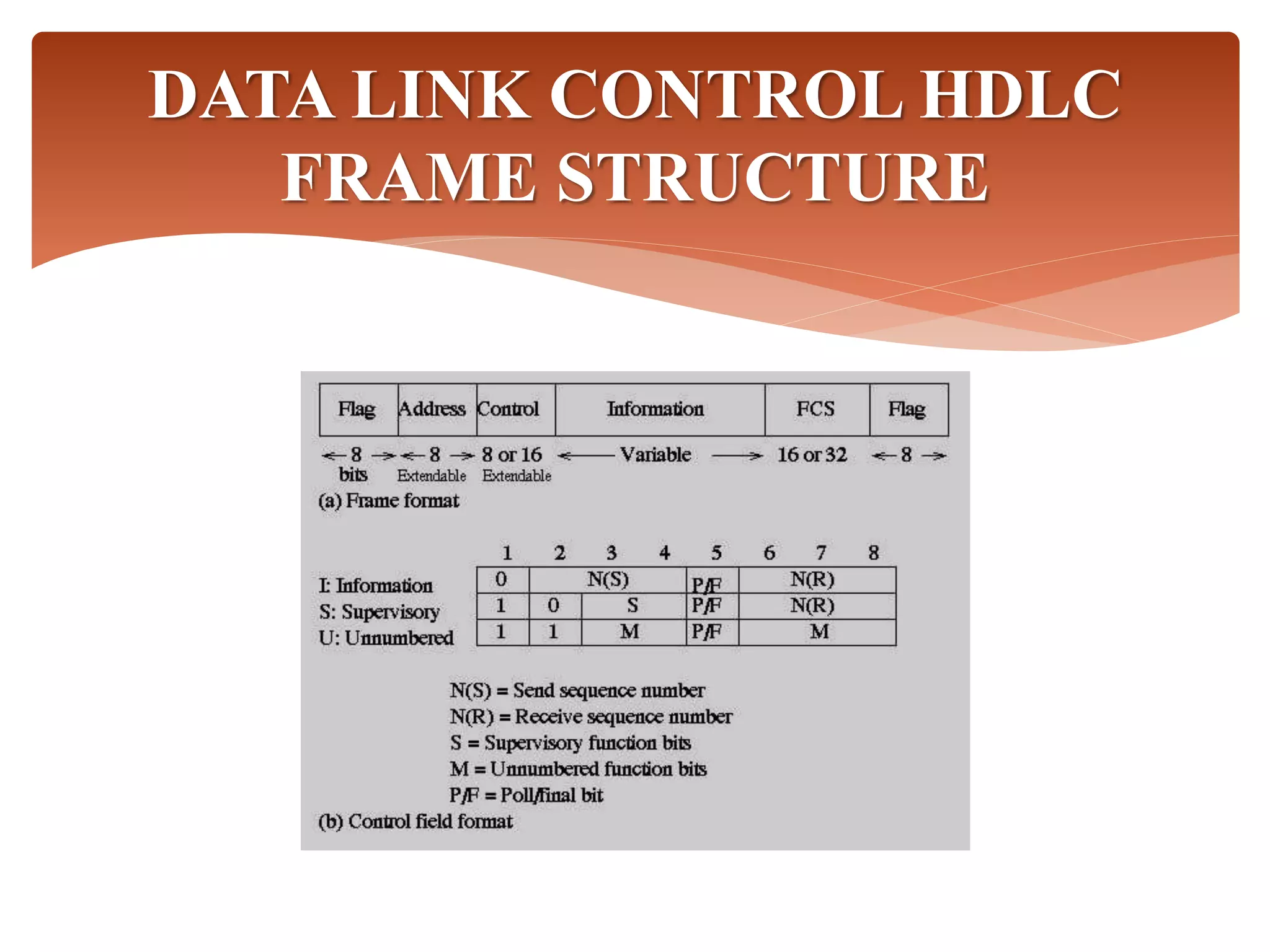
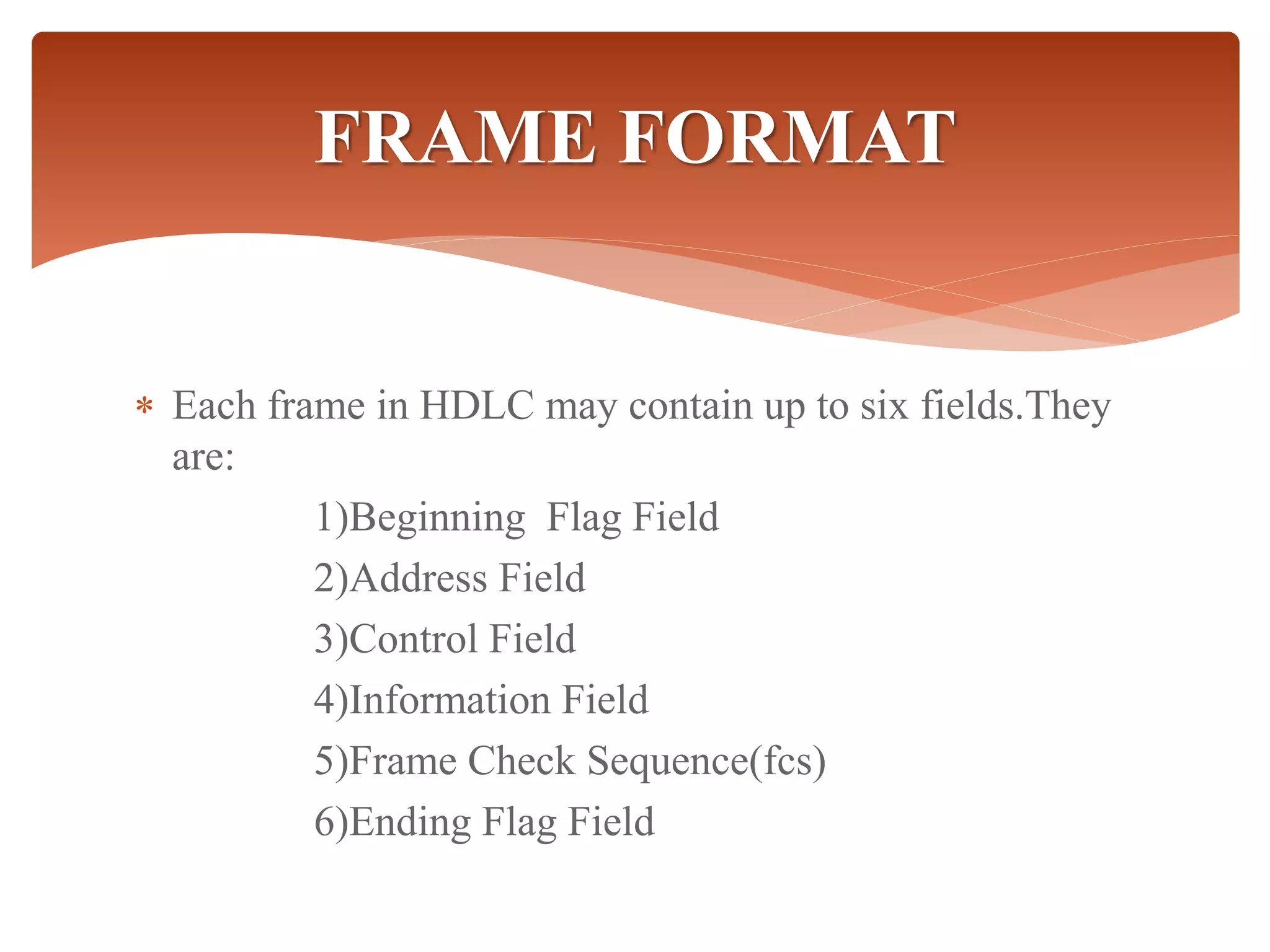
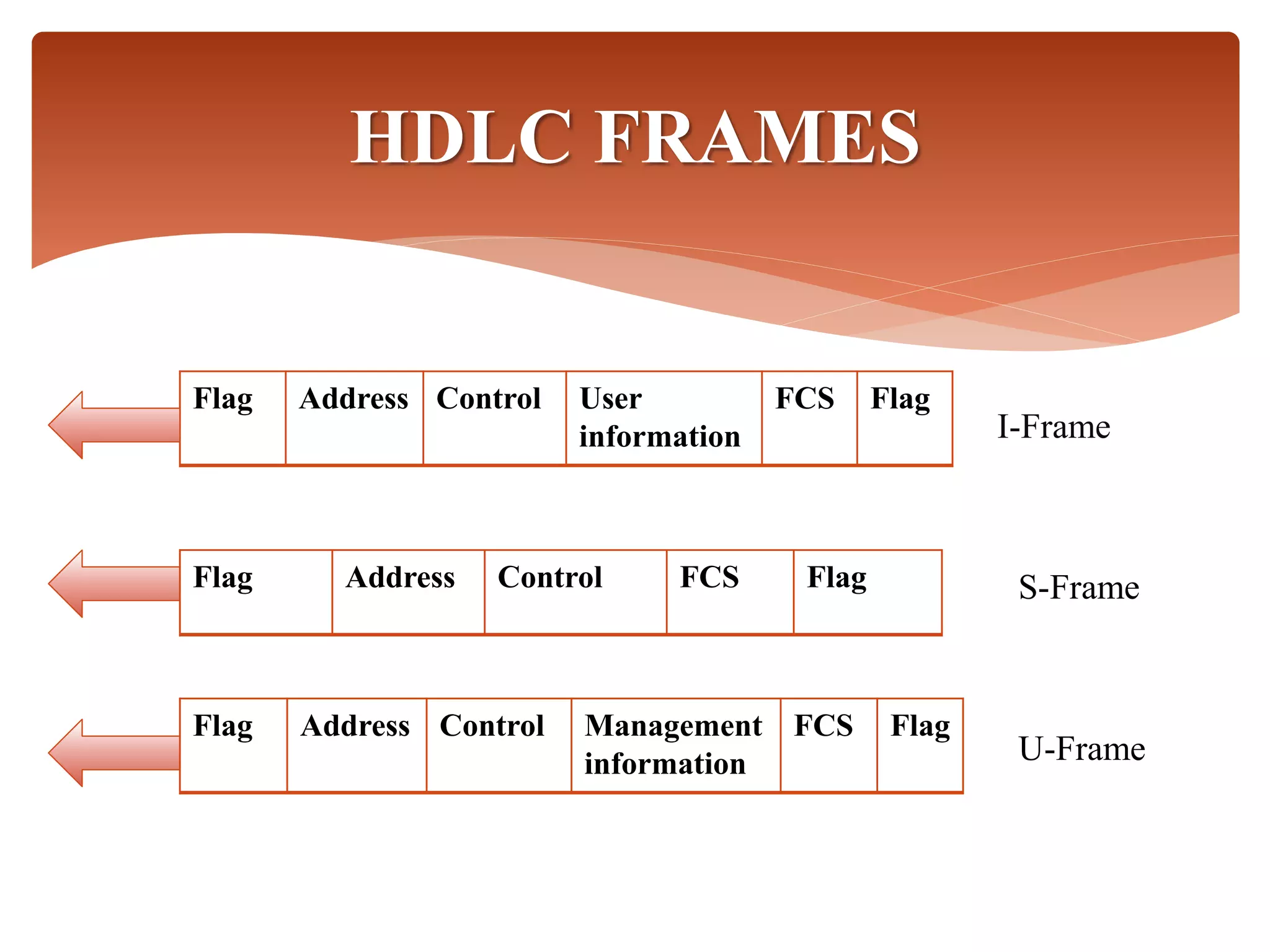
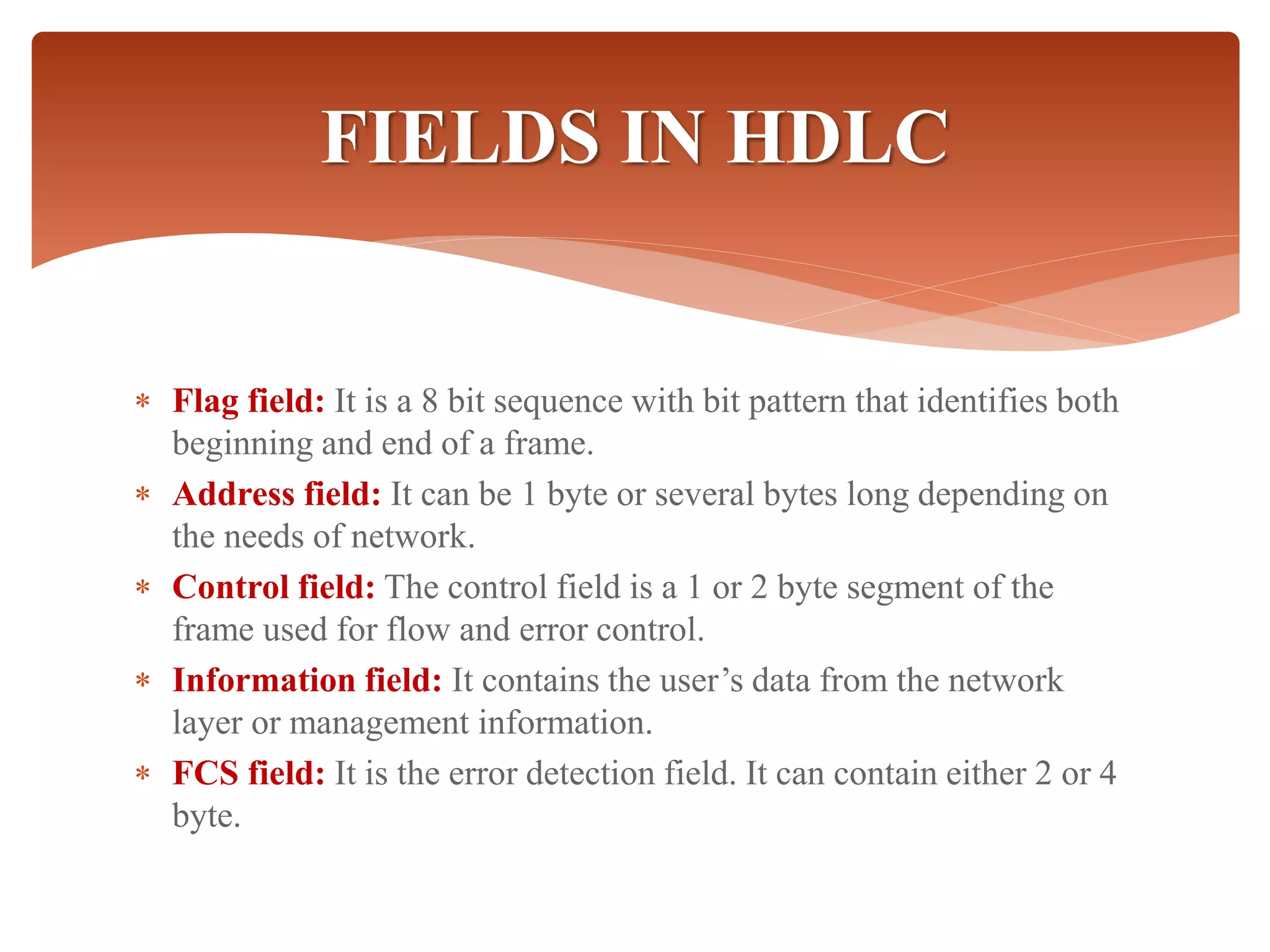
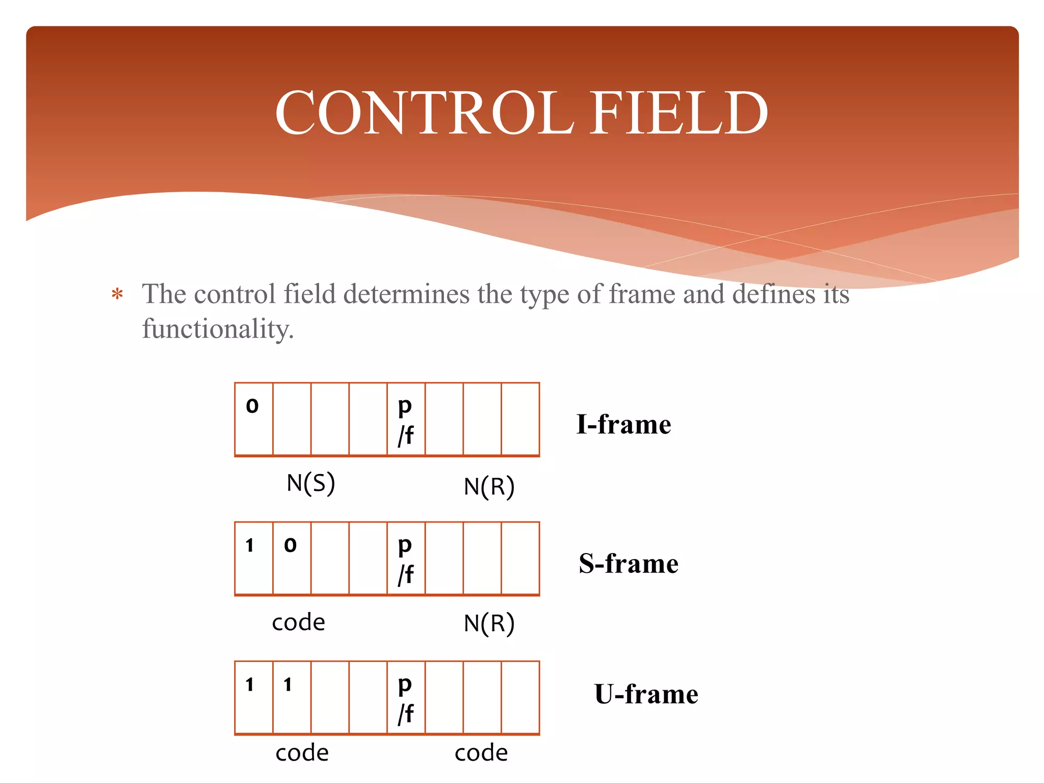
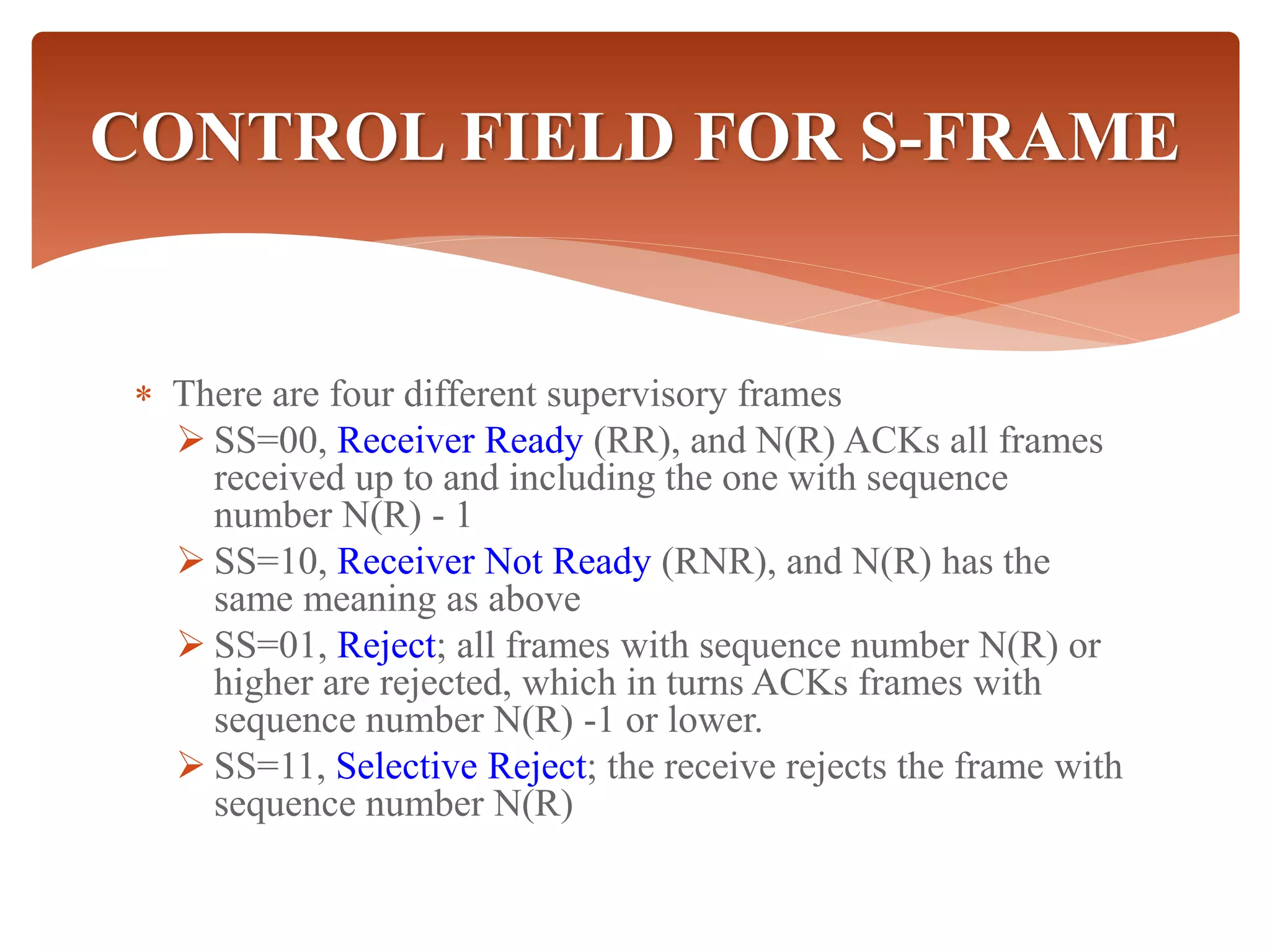
HIGH-LEVEL DATA LINK
CONTROL
BY
G.KARTHIGA M.SC INFOTECH
NADAR SARASWATHI COLLEGE OF ARTS
AND SCIENCE,THENI
 High level data link control(HDLC) is a bit
oriented protocol for communication over point-
to-point and multipoint link.
 It implements the AQR mechanism.
 HDLC provides both connectionless service and
connection oriented services.
 HDLC uses synchronous transmission. All
transmission are in the form of frames.
HDLC(High Level Data Link
Control)
 Defines three types of stations
 Primary
 Secondary
 Combined
 Defines three types of data transfer mode
 Normal Response mode
 Asynchronous Response mode
 Asynchronous Balanced mode
 Three types of frames
 information
 supervisory
 unnumbered
HDLC OVERVIEW
 The three modes of data transfer operations are
 Normal Response Mode (NRM)
 Mainly used in terminal-mainframe networks. In this case,
Secondary (terminals) can only transmit when specifically instructed
by the primary station in response to a polling.
 Unbalanced configuration, good for multi-point links
 Asynchronous Response Mode (ARM)
 Same as NRM except that the secondary can initiate transmissions
without direct polling from the primary station.
 Reduces overhead as no frames need to be sent to allow secondary
nodes to transmit.
 Transmission proceeds when channel is detected idle , used mostly in
point-to-point-links.
 Asynchronous Balanced Mode (ABM)
 Mainly used in point-to-point links, for communication between
combined stations.
DATA TRANSFER MODE
HDLC
Primary
Secondary
Secondary
Commands
Responses
Combined Combined
commands/Responses
Unbalanced Mode
Balanced mode
 There are three different classes of frames used in
HDLC
Unnumbered frames, used in link setup and
disconnection, and hence do not contain ACK.
Information frames, which carry actual information.
Such frames can piggyback ACK in case of ABM
Supervisory frames, which are used for error and flow
control purposes and hence contain send and receive
sequence numbers
FRAMES IN HDLC
DATA LINK CONTROL HDLC
FRAME STRUCTURE
FRAME FORMAT
 Each frame in HDLC may contain up to six fields.They
are:
1)Beginning Flag Field
2)Address Field
3)Control Field
4)Information Field
5)Frame Check Sequence(fcs)
6)Ending Flag Field
Flag Address Control User
information
FCS Flag
HDLC FRAMES
Flag Address Control Management
information
FCS Flag
I-Frame
S-Frame
U-Frame
Flag Address Control FCS Flag
 Flag field: It is a 8 bit sequence with bit pattern that identifies both
beginning and end of a frame.
 Address field: It can be 1 byte or several bytes long depending on
the needs of network.
 Control field: The control field is a 1 or 2 byte segment of the
frame used for flow and error control.
 Information field: It contains the user’s data from the network
layer or management information.
 FCS field: It is the error detection field. It can contain either 2 or 4
byte.
FIELDS IN HDLC
 The control field determines the type of frame and defines its
functionality.
CONTROL FIELD
0 p
/f
1 0 p
/f
1 1 p
/f
N(S) N(R)
code N(R)
code code
I-frame
S-frame
U-frame
 There are four different supervisory frames
 SS=00, Receiver Ready (RR), and N(R) ACKs all frames
received up to and including the one with sequence
number N(R) - 1
 SS=10, Receiver Not Ready (RNR), and N(R) has the
same meaning as above
 SS=01, Reject; all frames with sequence number N(R) or
higher are rejected, which in turns ACKs frames with
sequence number N(R) -1 or lower.
 SS=11, Selective Reject; the receive rejects the frame with
sequence number N(R)
CONTROL FIELD FOR S-FRAME

High level data link control

  • 1.
    HIGH-LEVEL DATA LINK CONTROL BY G.KARTHIGAM.SC INFOTECH NADAR SARASWATHI COLLEGE OF ARTS AND SCIENCE,THENI
  • 2.
     High leveldata link control(HDLC) is a bit oriented protocol for communication over point- to-point and multipoint link.  It implements the AQR mechanism.  HDLC provides both connectionless service and connection oriented services.  HDLC uses synchronous transmission. All transmission are in the form of frames. HDLC(High Level Data Link Control)
  • 3.
     Defines threetypes of stations  Primary  Secondary  Combined  Defines three types of data transfer mode  Normal Response mode  Asynchronous Response mode  Asynchronous Balanced mode  Three types of frames  information  supervisory  unnumbered HDLC OVERVIEW
  • 4.
     The threemodes of data transfer operations are  Normal Response Mode (NRM)  Mainly used in terminal-mainframe networks. In this case, Secondary (terminals) can only transmit when specifically instructed by the primary station in response to a polling.  Unbalanced configuration, good for multi-point links  Asynchronous Response Mode (ARM)  Same as NRM except that the secondary can initiate transmissions without direct polling from the primary station.  Reduces overhead as no frames need to be sent to allow secondary nodes to transmit.  Transmission proceeds when channel is detected idle , used mostly in point-to-point-links.  Asynchronous Balanced Mode (ABM)  Mainly used in point-to-point links, for communication between combined stations. DATA TRANSFER MODE
  • 5.
  • 6.
     There arethree different classes of frames used in HDLC Unnumbered frames, used in link setup and disconnection, and hence do not contain ACK. Information frames, which carry actual information. Such frames can piggyback ACK in case of ABM Supervisory frames, which are used for error and flow control purposes and hence contain send and receive sequence numbers FRAMES IN HDLC
  • 7.
    DATA LINK CONTROLHDLC FRAME STRUCTURE
  • 8.
    FRAME FORMAT  Eachframe in HDLC may contain up to six fields.They are: 1)Beginning Flag Field 2)Address Field 3)Control Field 4)Information Field 5)Frame Check Sequence(fcs) 6)Ending Flag Field
  • 9.
    Flag Address ControlUser information FCS Flag HDLC FRAMES Flag Address Control Management information FCS Flag I-Frame S-Frame U-Frame Flag Address Control FCS Flag
  • 10.
     Flag field:It is a 8 bit sequence with bit pattern that identifies both beginning and end of a frame.  Address field: It can be 1 byte or several bytes long depending on the needs of network.  Control field: The control field is a 1 or 2 byte segment of the frame used for flow and error control.  Information field: It contains the user’s data from the network layer or management information.  FCS field: It is the error detection field. It can contain either 2 or 4 byte. FIELDS IN HDLC
  • 11.
     The controlfield determines the type of frame and defines its functionality. CONTROL FIELD 0 p /f 1 0 p /f 1 1 p /f N(S) N(R) code N(R) code code I-frame S-frame U-frame
  • 12.
     There arefour different supervisory frames  SS=00, Receiver Ready (RR), and N(R) ACKs all frames received up to and including the one with sequence number N(R) - 1  SS=10, Receiver Not Ready (RNR), and N(R) has the same meaning as above  SS=01, Reject; all frames with sequence number N(R) or higher are rejected, which in turns ACKs frames with sequence number N(R) -1 or lower.  SS=11, Selective Reject; the receive rejects the frame with sequence number N(R) CONTROL FIELD FOR S-FRAME