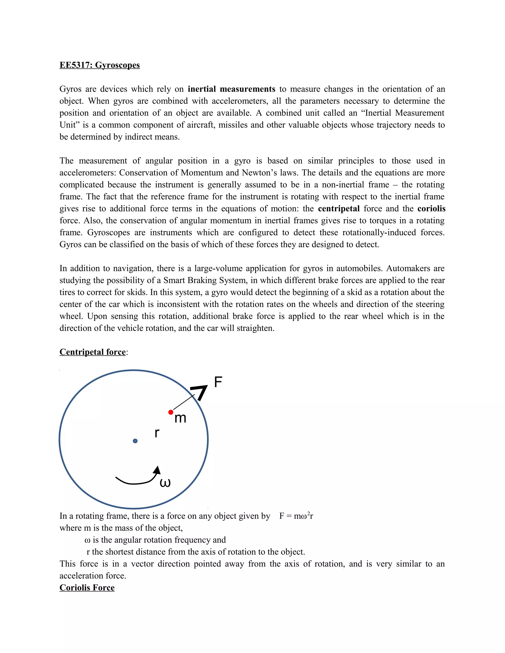
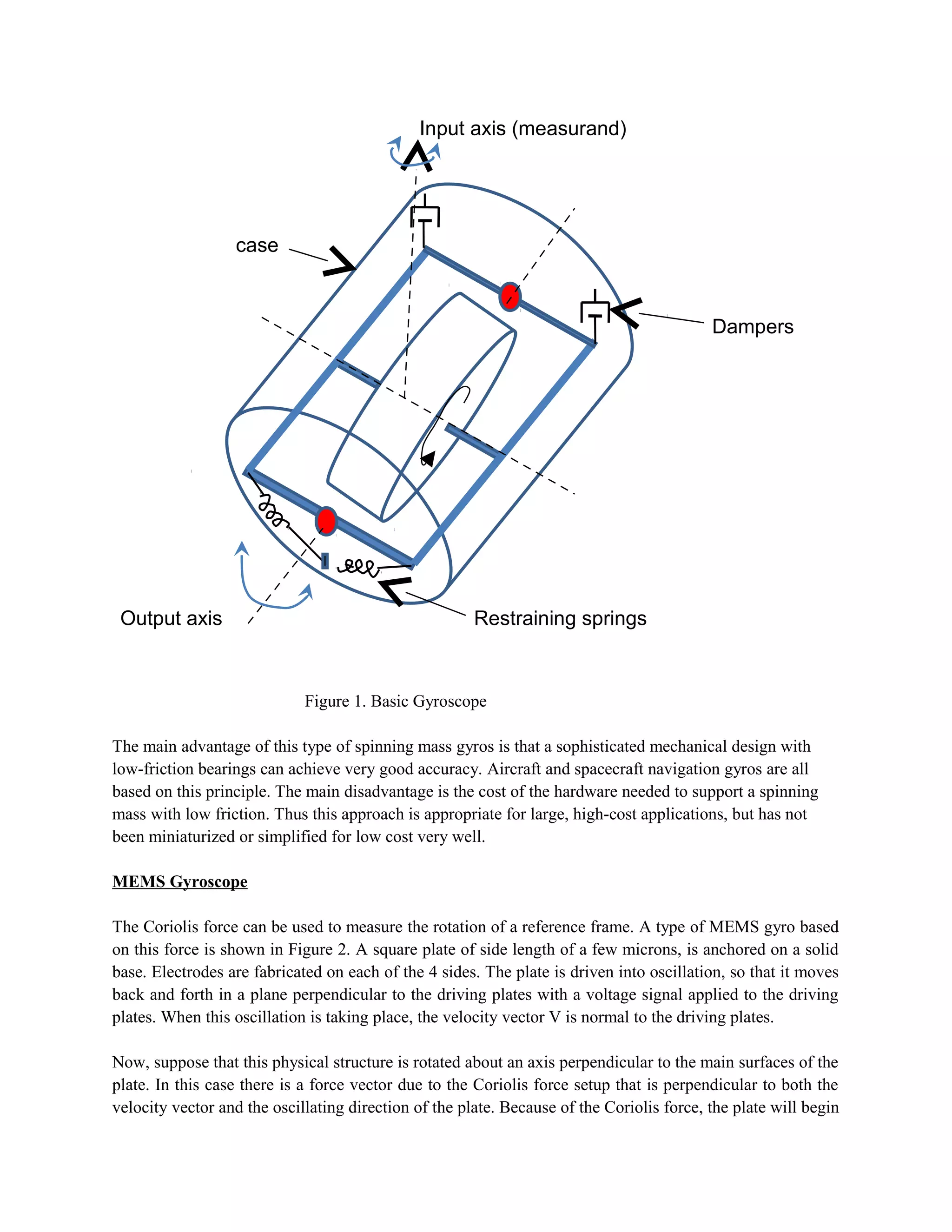
EE5317: Gyroscopes
Gyros are devices which rely on inertial measurements to measure changes in the orientation of an
object. When gyros are combined with accelerometers, all the parameters necessary to determine the
position and orientation of an object are available. A combined unit called an “Inertial Measurement
Unit” is a common component of aircraft, missiles and other valuable objects whose trajectory needs to
be determined by indirect means.
The measurement of angular position in a gyro is based on similar principles to those used in
accelerometers: Conservation of Momentum and Newton’s laws. The details and the equations are more
complicated because the instrument is generally assumed to be in a non-inertial frame – the rotating
frame. The fact that the reference frame for the instrument is rotating with respect to the inertial frame
gives rise to additional force terms in the equations of motion: the centripetal force and the coriolis
force. Also, the conservation of angular momentum in inertial frames gives rise to torques in a rotating
frame. Gyroscopes are instruments which are configured to detect these rotationally-induced forces.
Gyros can be classified on the basis of which of these forces they are designed to detect.
In addition to navigation, there is a large-volume application for gyros in automobiles. Automakers are
studying the possibility of a Smart Braking System, in which different brake forces are applied to the rear
tires to correct for skids. In this system, a gyro would detect the beginning of a skid as a rotation about the
center of the car which is inconsistent with the rotation rates on the wheels and direction of the steering
wheel. Upon sensing this rotation, additional brake force is applied to the rear wheel which is in the
direction of the vehicle rotation, and the car will straighten.
Centripetal force:
In a rotating frame, there is a force on any object given by F = mω2
r
where m is the mass of the object,
ω is the angular rotation frequency and
r the shortest distance from the axis of rotation to the object.
This force is in a vector direction pointed away from the axis of rotation, and is very similar to an
acceleration force.
Coriolis Force
F
ω
r
m
When in a rotating frame, there are a number of effects which can produce effects which produce
rotation-related forces. The centripetal force is one example. Another non-inertial force is the Coriolis
Force. We can feel this force for example, when walking about in a merry-go-round.
In general, when in a rotating frame, there is a force on all moving objects given by F= -2m ω (∂r/∂t)
This force is directed orthogonal to the velocity vector and the rotation vector. The “feel” of this force is
to deflect the trajectory of a moving object. If you walk outwards from the center of spinning merry-go-
round, spinning counter clock-wise when viewed from the top, there will be a force pushing you to the
right which increases as you move away from the center.
Conservation of Momentum Gyroscope: Figure 1 shows a standard configuration for a Conservation of
Angular Momentum gyro.
In this device, a spinning disk is supported by a low friction bearing, which is itself mounted by a gimbal
support to the frame of the instrument. Under most circumstances, the angular momentum vector (aligned
with the spin axis of the disk) will stay oriented in the same direction as viewed from an inertial reference
frame. Application of a rotational force about the input axis (orthogonal to both the spin and the gimbal
axis) exerts a torque on the spinning disk. Imposition of a torque along the axis orthogonal to the spin axis
results in a reaction torque about the axis orthogonal to the spin and torque axes. The instrument rotation
about the “input axis” causes a torque about the “output axis” which is measured by measuring the forces
on the support springs.
As viewed from the frame of the instrument, an applied rotation will lead to a torque on the spinning disk.
If the torque is about the gimbal axis as shown in the figure, the gimbal will rotate about this axis,
allowing the orientation of the spinning disk to remain fixed in the inertial frame. A measurement of the
rotation about the axis would yield a measurement of instrument rotation
F
ω
∂r/∂t
Figure 1. Basic Gyroscope
The main advantage of this type of spinning mass gyros is that a sophisticated mechanical design with
low-friction bearings can achieve very good accuracy. Aircraft and spacecraft navigation gyros are all
based on this principle. The main disadvantage is the cost of the hardware needed to support a spinning
mass with low friction. Thus this approach is appropriate for large, high-cost applications, but has not
been miniaturized or simplified for low cost very well.
MEMS Gyroscope
The Coriolis force can be used to measure the rotation of a reference frame. A type of MEMS gyro based
on this force is shown in Figure 2. A square plate of side length of a few microns, is anchored on a solid
base. Electrodes are fabricated on each of the 4 sides. The plate is driven into oscillation, so that it moves
back and forth in a plane perpendicular to the driving plates with a voltage signal applied to the driving
plates. When this oscillation is taking place, the velocity vector V is normal to the driving plates.
Now, suppose that this physical structure is rotated about an axis perpendicular to the main surfaces of the
plate. In this case there is a force vector due to the Coriolis force setup that is perpendicular to both the
velocity vector and the oscillating direction of the plate. Because of the Coriolis force, the plate will begin
case
Input axis (measurand)
Output axis
Dampers
Restraining springs
to oscillate in the direction normal to the direction of the oscillating plate. This oscillation is detected by
the sensing plates. The voltage induced on the sensing plates will indicate the amount of rotation of the
structure.
Figure 2.

Gyroscopes

  • 1.
    EE5317: Gyroscopes Gyros aredevices which rely on inertial measurements to measure changes in the orientation of an object. When gyros are combined with accelerometers, all the parameters necessary to determine the position and orientation of an object are available. A combined unit called an “Inertial Measurement Unit” is a common component of aircraft, missiles and other valuable objects whose trajectory needs to be determined by indirect means. The measurement of angular position in a gyro is based on similar principles to those used in accelerometers: Conservation of Momentum and Newton’s laws. The details and the equations are more complicated because the instrument is generally assumed to be in a non-inertial frame – the rotating frame. The fact that the reference frame for the instrument is rotating with respect to the inertial frame gives rise to additional force terms in the equations of motion: the centripetal force and the coriolis force. Also, the conservation of angular momentum in inertial frames gives rise to torques in a rotating frame. Gyroscopes are instruments which are configured to detect these rotationally-induced forces. Gyros can be classified on the basis of which of these forces they are designed to detect. In addition to navigation, there is a large-volume application for gyros in automobiles. Automakers are studying the possibility of a Smart Braking System, in which different brake forces are applied to the rear tires to correct for skids. In this system, a gyro would detect the beginning of a skid as a rotation about the center of the car which is inconsistent with the rotation rates on the wheels and direction of the steering wheel. Upon sensing this rotation, additional brake force is applied to the rear wheel which is in the direction of the vehicle rotation, and the car will straighten. Centripetal force: In a rotating frame, there is a force on any object given by F = mω2 r where m is the mass of the object, ω is the angular rotation frequency and r the shortest distance from the axis of rotation to the object. This force is in a vector direction pointed away from the axis of rotation, and is very similar to an acceleration force. Coriolis Force F ω r m
  • 2.
    When in arotating frame, there are a number of effects which can produce effects which produce rotation-related forces. The centripetal force is one example. Another non-inertial force is the Coriolis Force. We can feel this force for example, when walking about in a merry-go-round. In general, when in a rotating frame, there is a force on all moving objects given by F= -2m ω (∂r/∂t) This force is directed orthogonal to the velocity vector and the rotation vector. The “feel” of this force is to deflect the trajectory of a moving object. If you walk outwards from the center of spinning merry-go- round, spinning counter clock-wise when viewed from the top, there will be a force pushing you to the right which increases as you move away from the center. Conservation of Momentum Gyroscope: Figure 1 shows a standard configuration for a Conservation of Angular Momentum gyro. In this device, a spinning disk is supported by a low friction bearing, which is itself mounted by a gimbal support to the frame of the instrument. Under most circumstances, the angular momentum vector (aligned with the spin axis of the disk) will stay oriented in the same direction as viewed from an inertial reference frame. Application of a rotational force about the input axis (orthogonal to both the spin and the gimbal axis) exerts a torque on the spinning disk. Imposition of a torque along the axis orthogonal to the spin axis results in a reaction torque about the axis orthogonal to the spin and torque axes. The instrument rotation about the “input axis” causes a torque about the “output axis” which is measured by measuring the forces on the support springs. As viewed from the frame of the instrument, an applied rotation will lead to a torque on the spinning disk. If the torque is about the gimbal axis as shown in the figure, the gimbal will rotate about this axis, allowing the orientation of the spinning disk to remain fixed in the inertial frame. A measurement of the rotation about the axis would yield a measurement of instrument rotation F ω ∂r/∂t
  • 3.
    Figure 1. BasicGyroscope The main advantage of this type of spinning mass gyros is that a sophisticated mechanical design with low-friction bearings can achieve very good accuracy. Aircraft and spacecraft navigation gyros are all based on this principle. The main disadvantage is the cost of the hardware needed to support a spinning mass with low friction. Thus this approach is appropriate for large, high-cost applications, but has not been miniaturized or simplified for low cost very well. MEMS Gyroscope The Coriolis force can be used to measure the rotation of a reference frame. A type of MEMS gyro based on this force is shown in Figure 2. A square plate of side length of a few microns, is anchored on a solid base. Electrodes are fabricated on each of the 4 sides. The plate is driven into oscillation, so that it moves back and forth in a plane perpendicular to the driving plates with a voltage signal applied to the driving plates. When this oscillation is taking place, the velocity vector V is normal to the driving plates. Now, suppose that this physical structure is rotated about an axis perpendicular to the main surfaces of the plate. In this case there is a force vector due to the Coriolis force setup that is perpendicular to both the velocity vector and the oscillating direction of the plate. Because of the Coriolis force, the plate will begin case Input axis (measurand) Output axis Dampers Restraining springs
  • 4.
    to oscillate inthe direction normal to the direction of the oscillating plate. This oscillation is detected by the sensing plates. The voltage induced on the sensing plates will indicate the amount of rotation of the structure. Figure 2.