Downloaded 48 times


![Example 2: Parabolic dish antenna is commonly used in higher frequencies
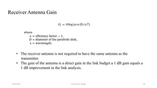
Gain of Parabolic antenna: Gt = 10 log[ n( πD/λ)2 ]
Note:
• Antenna gain increases both with increasing diameter and frequency.
10/3/2015 Transceiver Design 9](https://image.slidesharecdn.com/transceiverdesign-150502130548-conversion-gate02/85/Transceiver-design-9-320.jpg)
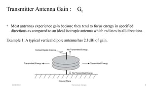
![10/3/2015 Transceiver Design 15
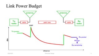
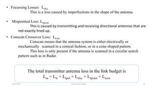
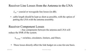
Free Space Attenuation:
This loss is due to dispersion, the ”spreading out” of the beam of radio energy as it
propagates through space.
The main contributor to channel loss is free-space attenuation.
Figure from http://en.wikipedia.org/wiki/Inverse_square
Afs = 20log[4Rf/c]
where:
Afs = free-space loss
R = slant range (same units as ),
f = frequency of operation,
c = speed of light, 300 × 106 m/sec, R is in meters.](https://image.slidesharecdn.com/transceiverdesign-150502130548-conversion-gate02/85/Transceiver-design-15-320.jpg)
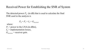

This document discusses the key parameters in designing a transceiver system. It describes the components in the transmitter and receiver paths that impact the link budget, including transmitter power output, gains and losses, noise figure, and signal-to-noise ratio. Key transmitter components are the power amplifier, transmission line, and antenna. Key receiver components are the antenna, low-noise amplifier, and additional amplifiers. The document provides equations to calculate link budget parameters like effective isotropic radiated power, received signal power, and noise level.


![Multiband Transceivers - [Chapter 6] Multi-mode and Multi-band Transceivers](https://cdn.slidesharecdn.com/ss_thumbnails/ch6-150613070935-lva1-app6891-thumbnail.jpg?width=640&height=640&fit=bounds)


![RF Circuit Design - [Ch2-2] Smith Chart](https://cdn.slidesharecdn.com/ss_thumbnails/ch2-2-150613064401-lva1-app6891-thumbnail.jpg?width=640&height=640&fit=bounds)


