Downloaded 735 times

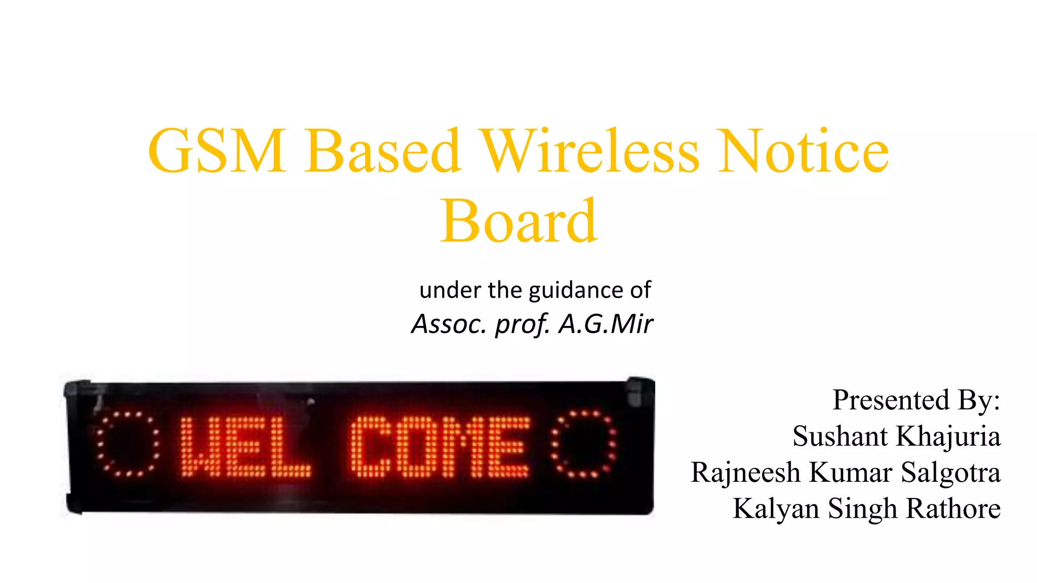
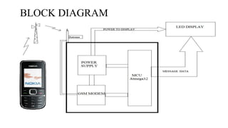
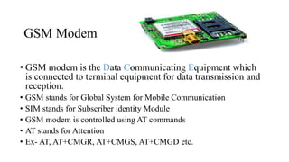
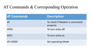
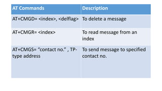
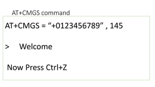
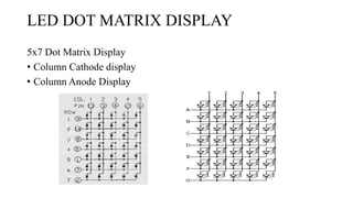
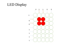
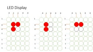
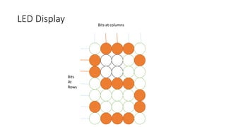
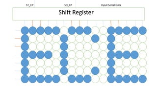
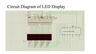
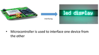
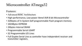
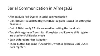
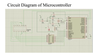
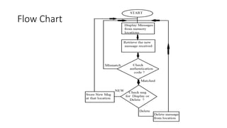


The document presents a GSM-based wireless notice board project, detailing its components such as GSM modems, microcontrollers, and LED displays. It includes information about AT commands for operating the modem, circuit diagrams, and the potential applications of the system for various communication needs. Suggestions for improvements and security enhancements are also provided, underscoring the project's adaptability for use in different environments.


