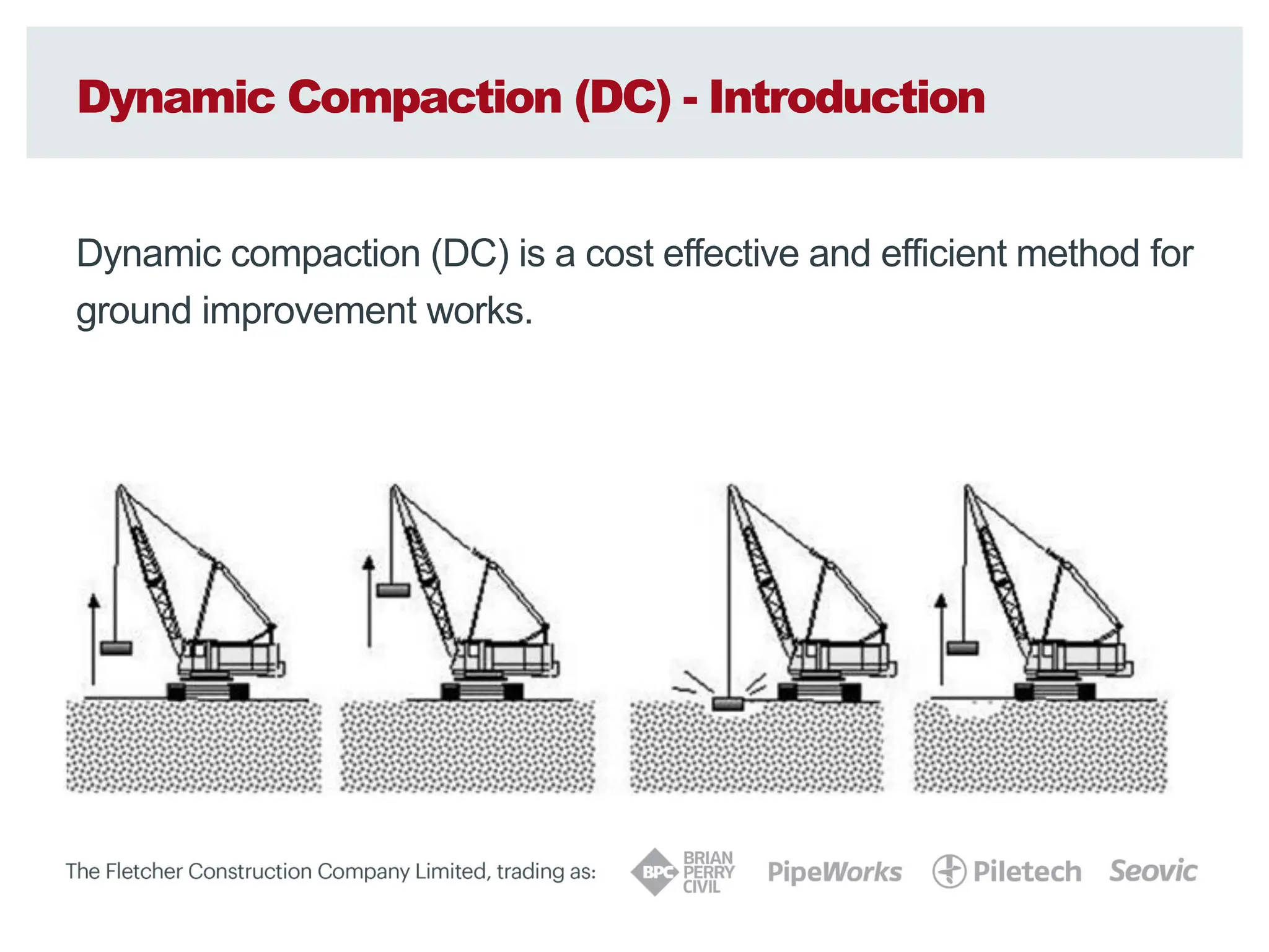
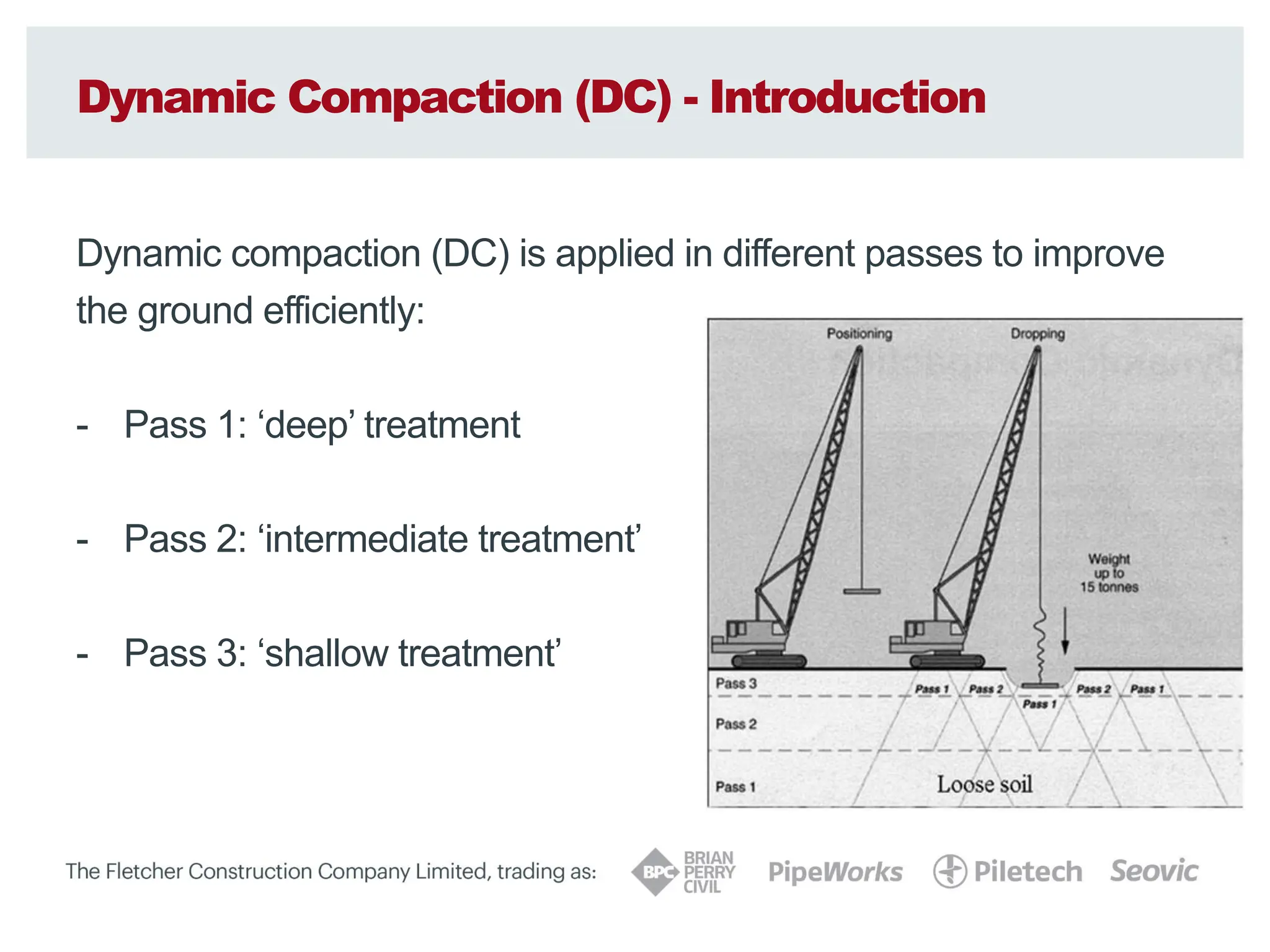
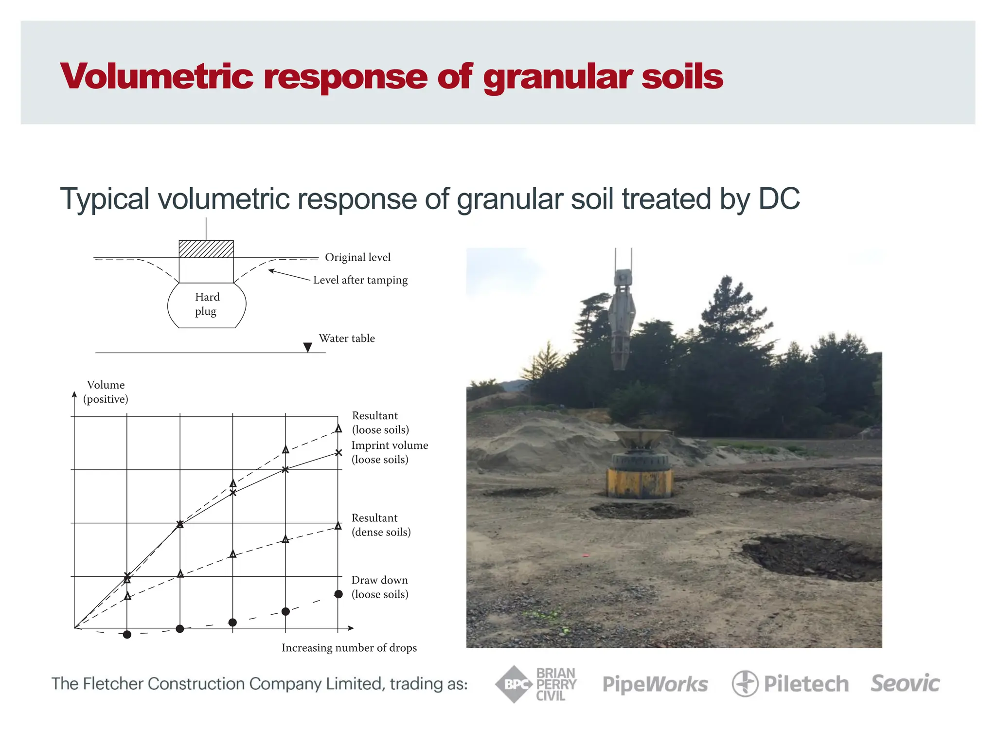
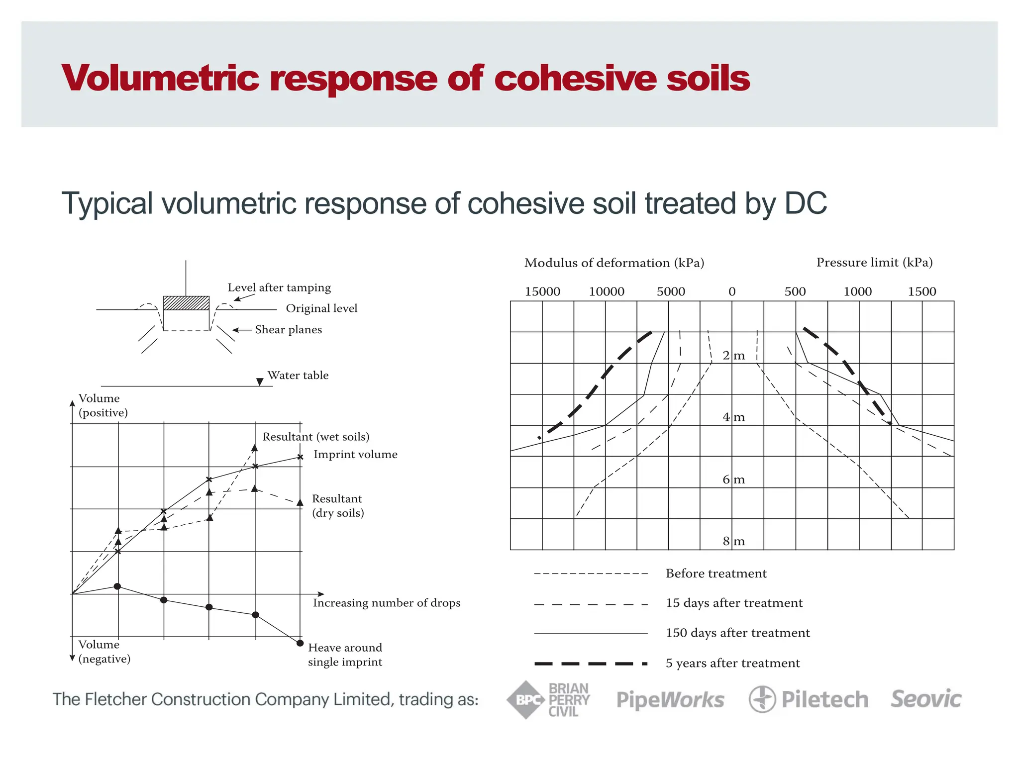
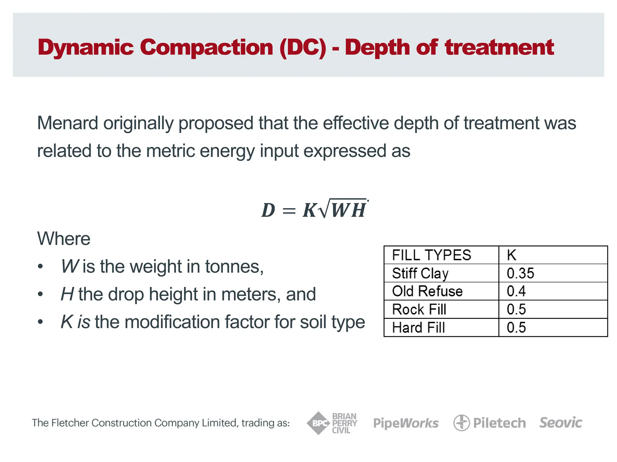
SlideShare a Scribd company logo
1 of 76
Download to read offline
Martin Larisch & Tim Pervan
Ground Improvement
Techniques:
Dynamic Compaction
INSERT DATE HERE
Ground Improvement - What is it?
Ground Improvement = Black Box?
Ground Improvement - Introduction
Ground Improvement
Improve the existing soil formation by changing the soil properties by
mechanical or chemical treatment.
Ground improvement doesn’t create structural elements (like piles)
to ‘bridge’ unsuitable soil layers but it improves the ground itself to
allow for shallow foundations.
Ground improvement is mainly used for:
- Settlement reduction / control
- Liquefaction mitigation
Fletcher Construction Company
Brian Perry Civil
Established in1954
in Hamilton
Head office today
in Auckland (Penrose).
Branches in:
- Hamilton
- Auckland
- Christchurch
- Wellington
Brian Perry Civil
Four branches around New Zealand
• 350 employees (80 engineers)
• Turnover $230m
Our Focus
• Self performing, high-risk
civil engineering contracting
• Projects up to $50m
• Smart use of technology
• Drive innovation and strong
client focus
Auckland
Hamilton
Wellington
Christchurch
Areas of Expertise
Ground Improvement - Methods
Overview of some ground improvement methods:
• Vibro compaction
• Vibro replacement
• Soil mixing
– Jet grouting
– Deep soil mixing (vertical)
– Deep soil mixing (horizontal / block)
• Rigid Inclusions
• Dynamic replacement
• Dynamic compaction
Vibro Compaction (VC) - Introduction
Vibro compaction (VC) is a cost effective GI method which
allows to specifically target deeper treatment areas.
Vibro compaction (VC) - Introduction
Vibro compaction
Vibro Compaction (VC) – Suitable Soils
Vibro compaction (VC) – Suitable Soils
Vibro replacement (VR) vs Vibro compaction (VC)
Vibro replacement (VR) - Introduction
Vibro replacement (wet top feed)
Vibro replacement (VR) - Introduction
Vibro replacement (dry bottom feed)
Vibro replacement (VR) – Suitable Soils
Vibro replacement (VR) Methods - CAUTION
Methodologies:
• Vertical movements
(sheet piling probe)
• Lateral movements
(VR probe)
• Different performance
in similar (granular)
ground conditions
Deep Soil Mixing (DSM) - Introduction
Deep Soil Mixing (DSM)
Deep Soil Mixing (DSM) - Introduction
Deep Soil Mixing (DSM) - vertical columns
Deep Soil Mixing (DSM) - Vertical columns
• Good mixing quality also in plastic clay
• Precise diameter and good verticality
• High production rates
• By limiting the jetting pressures, the cement content, the resulting
column strength and the column modulus are relatively constant
• Column diameter: 600 to 1000 mm
• Column depth: typically up to 15m, greater depths are possible
depending on rig size, soil properties, column diameter and
consistency
• Column strengths between 0.5 MPa and 2 MPa are typical,
depending on ground conditions, mixing time and cement content
Continuous Flight Auger (CFA) - Introduction
CFA lattice structures - vertical columns
Deep Soil Mixing (DSM) - Introduction
Deep Soil Mixing (DSM) - mass mixing
Deep Soil Mixing (DSM) - Mass mixing
• Good mixing quality in granular soils
• High production rates
• The cement content, the resulting ‘soilcrete’ strength and the
‘soilcrete’ modulus are relatively constant
• Panel width: 600 to 1500 mm
• Panel depth: typically up to 5m, greater depths are possible
depending on rig size, soil properties
• ‘Soilcrete’ strengths between 0.5 MPa and 2 MPa are typical,
depending on ground conditions, mixing time and cement content
Rigid Inclusions (RI) - Introduction
Rigid Inclusions with Drilled Displacement Piling (DDP) methods
Innovative methodology with potential for liquefaction mitigation
Rigid Inclusions (RI) - Installation effects
Rigid Inclusions with Drilled Displacement Piling (DDP) methods
Installation effects are critical for soil densification!
Working platform Working platform
Liquefiable layer Liquefiable layer
Rigid Inclusions (CMC, CSC, DDP) - Introduction
• Densification potential in loose granular soils if penetration rate is
sufficient and auger geometry is suitable
• Penetration of hard layers possible
• High production rates
• The use of concrete (usually 5 to 15 MPa) keeps the column
modulus very constant
• Column diameters:
– 450mm to 900 mm for non-displacement techniques
– 360mm to 450mm for drilled displacement techniques
• Column depth: typically up to 25m, greater depths are possible
depending on rig size, soil properties
Dynamic Compaction (DC) - Introduction
Dynamic compaction (DC) is a cost effective and efficient method for
ground improvement works.
Dynamic Compaction (DC) - Introduction
Dynamic compaction (DC) strengthens weak soils by controlled high-
energy tamping (dropping a static weight from a defined height).
The reaction of the soil during the treatment varies with soil type and
energy input.
Typically drop weights range from 6-20 ton dropped from heights up
to 20m. Weights are typically constructed using steel plates, box steel
and concrete (also suitably reinforced mass concrete).
Dynamic Replacement (DR) - Overview
Dynamic replacement (DR) is another cost effective GI method.
Dynamic Compaction (DC) - Introduction
Dynamic compaction (DC) is applied in different passes to improve
the ground efficiently:
- Pass 1: ‘deep’ treatment
- Pass 2: ‘intermediate treatment’
- Pass 3: ‘shallow treatment’
Dynamic Compaction (DC) - Introduction
Dynamic compaction (DC) is applied in different passes to improve
the ground efficiently:
- Pass 1: ‘deep’ treatment
- Pass 2: ‘intermediate treatment’
- Pass 3: ‘shallow treatment’
Dynamic Compaction (DC) - Introduction
Dynamic compaction (DC) is applied in different passes to improve
the ground efficiently:
- Pass 1: ‘deep’ treatment
- Pass 2: ‘intermediate treatment’
- Pass 3: ‘shallow treatment’
Dynamic Compaction (DC) - Design requirements
It is important to understand the design requirements of your project in
order to determine the best treatment / solution:
- Bearing capacity
- Settlement improvement
- Liquefaction mitigation
- Long term performance
- Other (e.g. backfilling landfill sites or collapsing cavities)
Is a load transfer / distribution layer required?
Dynamic Compaction (DC) - Suitable soil groups
Soil groups (typically) suitable for treatment by Dynamic Compaction
General Soil Type Degree of Saturation Suitability for DC
Granular deposits in the grain size range of
boulders to sand with 0% passing the 0.074mm
sieve
High or Low Excellent
Granular deposits containing not more than
35% silts
High Good
Low Excellent
Semi-permeable soil deposits, generally silty
soils containing some sands but less than 25%
clay with PI<8
High Fair
Low Good
Impermeable soil deposits generally clayey
soils where PI>8
High Not Recommended
Low Fair-minor improvements water
content should be less than
plastic limit
Miscellaneous fill including paper, organic
deposits, metal and wood
Low Fair-long term settlement
anticipated due to decomposition.
Limit use to embankments
Highly organic deposits peat-organic silts High Not recommended unless
sufficient energy applied to mix
granular with organic soils
Working principle - Granular soils
In dry granular materials tampering improves engineering properties
of the soil.
Physical displacement of particles and low-frequency excitation will:
- reduce the void ratio and
- increase the relative density
to provide improved load bearing and enhanced settlement criteria.
The existing density and grading of the soil are major factors how
efficiently a granular soil deposit can be improved.
Working principle - Granular soils (high energy)
Below the ground water table and after a suitable number of surface
impacts, pore pressure rises to a sufficient level to introduce
liquefaction.
Low frequency vibrations caused by further stress impulses will then
re-organise the particles into a denser state.
Dissipation of pore water pressures in conjunction with the effective
surcharge of the liquefied layer by the soils above, results in further
increase in relative density over a relatively short time period.
(1-2 days in well graded sands to 1-2 weeks in silty sands)
Working principle - Granular soils (low energy)
DC can be used without inducing the liquefied state (which is almost
impossible in loose sandy deposits with high ground water tables…)
The treatment without liquefaction is aimed to provide compaction by
displacement without dilation or high excess pore pressure by using a
smaller number of drops from a lower drop height.
This approach, where applicable, requires significantly lower energy
input than the liquefaction approach with consequent economies.
Volumetric response of granular soils
Typical volumetric response of granular soil treated by DC
Working principle - Cohesive soils
The mechanism for achieving improvements of:
- cohesive natural soils,
- soft near-saturated clay fill or
- recent hydraulically placed fill
is more complex than that of granular soils. With conventional
consolidation theory, a static surcharge loading will collapse voids
within clay fills and expel water to induce consolidation and increase
strength. The rate at which this occurs is dependent upon the
imposed load, coefficient of consolidation, and length of drainage
path.
Working principle - Cohesive soils
In contrast, dynamic compaction applies a virtually instant localised
surcharge that collapses voids and transfers energy to the pore water.
This creates zones of a positive water pressure gradient that forces
water to rapidly drain from the soil matrix. This effect is accelerated
further by the formation of additional drainage paths through shear
and hydraulic failure of the soil as the weight hits the ground.
Consolidation therefore occurs more rapidly and literally squeezes the
water out of the soil to effectively ‘pre-loading’ the ground.
Working principle - Cohesive soils
The treatment of cohesive soil above the ground water table can lead
to significant improvements in bearing capacity.
Cohesive soils below the ground water table, a larger reduction of the
moisture content is required in the presence of a smaller available
pore-pressure gradient and a longer drain path.
Only nominal degrees of improvement have been achieved in thick
layers of relatively weak saturated clays and silts, even with additional
measures like wick drains, stone columns or aggregate filled trenches.
Volumetric response of cohesive soils
Typical volumetric response of cohesive soil treated by DC
Dynamic Compaction (DC) - Depth of treatment
Menard originally proposed that the effective depth of treatment was
related to the metric energy input expressed as
𝑫 = 𝑲 𝑾𝑯
.
Where
• W is the weight in tonnes,
• H the drop height in meters, and
• K is the modification factor for soil type
Dynamic Compaction (DC) - Depth of treatment
It is important to understand the project requirements as kinetic
energy impact at the point of treatment is critical in depth treatment
and increasing the drop height will increase the velocity.
The shape of the improvement in the ground tends to be similar to
the Boussinesq distribution of stress for a circular foundation.
Modification of energy levels at each tamping pass can be used to
custom-design the treatment scheme to a specific soil profile and
engineering requirement.
Dynamic Compaction (DC) - Depth of treatment
The figure below suggests that factors as high as 0.9 could apply for
shallow depths of loose granular soils (typical values are lower)
Dynamic Compaction (DC) - Quality control
It is normal procedure to test treated ground during the progress of the
compaction works for control purposes to assess the effectiveness of the
treatment. This provides the designer with assurance that the specified level
of compaction will achieve the degree of improvement required. Quality
control testing during treatment often involves in-situ penetration tests
(e.g. CPT or SPT) which may form part of the final assurance testing. Test
methods, frequency of testing and criteria for acceptance should be agreed at
tender stage. The frequency of testing will be affected by factors particular to
each project, for example, the variability of the ground before treatment, the
nature of the structure to be supported and its sensitivity to post-treatment
movements.
Ground Improvement - Summary
- It is important to fully understand the design requirements
- It is important to understand the ground improvement methodology
and it’s specific advantages and limitations
- Dynamic compaction can be very effective in granular soils
- High energy
- Low energy
- Dynamic compaction can be used with caution in cohesive soils
and soils with organic layers
- Noise and vibration effects of different ground improvement
techniques must be considered and how these can be managed
- New technologies offer greater opportunities and unknown risks
Project Example
M2PP Alliance
DC Project Example – M2PP
MacKay’s to Peka Peka Expressway
• 18km Long 4 lane expressway
• 15 road bridges the longest being 250m
across the Waikanae River
• 2 significant pedestrian overpass bridges
• Project Value = $600M NZD
M2PP – Geology and Seismicity
• Design PGA up to 0.98g in a
1/2500 year ULS event.
• Extensive sections underlain by
potentially liquefiable dune
sands and silts
M2PP – Geology and Seismicity
• Approximately 50% of the
earthwork footprint is
underlain by peat.
• Ground water levels are near
surface
Design Requirements
• Displacement based design
adopted for all bridges
• Ground Improvement used
under bridge abutments to
control seismically induced
displacements of bridge
abutment soil.
• Displacements typically
between 100mm – 200mm.
Design Requirements
• Ground Improvement Methods – Considered at Design Stage
– Gravel (stone) Columns
– Concrete / In situ mix lattice
– Vibro Compaction – Latter Changed to Dynamic Compaction
Stone Columns
Design Philosophy
• Stone Columns & Vibro Densification
– Improve sandy or gravelly soils
– Intent was to densify surrounding soils – increasing horizontal effective stress
– Shear stiffening and drainage effects not incorporated
– Verification using CPT qt curves based on FOSliq = 1.0 and 1.2
– Curves based on 2500 year return period
W:DESIGNGeotechnical - Detailed Design5. Detailed Design5.6 BridgesD470 - WAI2. Working2.4 AnalysisLiquefactionGround ImprovementDensification CriteriaDesign Densification Criteria run 5.xlsx
0 5 10 15 20 25 30 35 40 45 50
0
5
10
15
0 5 10 15 20 25
Equivalent SPT (N1)60 (blows/300mm)
Depth
Below
Finished
Ground
Level
(m)
CPT qt (MPa)
Site Class D - 2500yr Return Period - Minimum Penetration Resistance
TOC qt Design Curve
Minimum qt, FOS(liq)=1.0
Minimum Average qt, FOS(liq)=1.2
Correlated Equivalent Minimum SPT (N1)60, FOS(liq)=1.0
Correlated Equivalent Minimum Average SPT (N1)60, FOS(liq)=1.2
Stone Columns
• Construction method
– Top feed columns using wet flush method
– 65/40 gap graded ballast
– 2000m3 U bend pounds
• Column Size and Spacing
– Design - 600mm diameter columns at a 35% replacement ratio
– Trialed varying spacing's (1.85m, 1.7m, 1.5m)
– Final - 900mm diameter columns at 32.6% replacement ratio
Stone Columns
• Results
– Good response in sands and gravels
– Poor response in silt layers
– Column Diameter varied between 900mm
and 1100mm
-10
-9
-8
-7
-6
-5
-4
-3
-2
-1
0
1
0.0 5.0 10.0 15.0 20.0 25.0 30.0 35.0
Depth
Below
Finished
Ground
level
(mRL)
qt (MPa)
470 Pre & Post CPTs vs Target (1:2500yr Class D Minimum
Penetration Resistance)
Minimum Corrected Cone Resistance (qt) Mpa
Minimum Average Corrected Cone Resistance (qt) Mpa
Top of Treatment
CFA Concrete Lattice
Design Philosophy
• CFA Concrete Lattice
– Sites containing silty soils unsuitable for improvement by stone columns
– Improvement by increasing the cyclic stiffness in composite action.
– Design based on the stress re-distribution method – Baez & Martin (1994)
– OTREC (2013) design approach used applying a reduction factor to account for partial shear and
flexural behavior considering all lattice elements.
– Verification of lattice strength by converting Glat – Emod – UCS for on site testing
s
on ‘S’ in Figure 3) is defined by the required area ratio, limited to a maximum
e based on observations of reducing effectiveness at greater dimensions
ers Siddharthan & Porbaha (2008). A continuous perimeter panel is also
ire improvement block.
nels
s (dimension ‘t’ in Figure 3) is a function of the proposed construction method
tio. The thickness is expected to range between 0.5 and 1.0m, with the actual
rawings.
g construction methods, the maximum centre to centre spacing between the
hieve a suitable minimum overlap) will also be specified on the drawings.
Figure 3: Lattice Grid: Unit C
Figure 3: Lattice Grid: Unit Cell and
ell and
ell and
ell and D
D
D
Dimensions
imensions
imensions
imensions
NORTH
ABUTMENT
NORTH
BOUND
SOUTH
BOUND
4400 4400 4400 4400 4400 4400 4400 4400
4400
4400
4400
4400
235
2240
2110
750
TYP.
750
TYP.
750
S.O.P. 3
S.O.P. 4
CONCRETE LATTIC
STEEL H-PILES
35200
10228
10564
17600
EXTENT OF PILE C
NEW H-PILES NEW H-PILES
0mm
20
40
60
80
100
A1
REPRODUCTION
SCALE
Concrete Lattice
• Initial design requirements
– Shear stiffness = 400kPa
– Elastic Modulus = 960kPa
– UCS = 1200kPa
• Soil Mixing Laboratory Trials
– Mix ratio’s = 6%, 9%, 12%, 20% by weight
– W/C Ratios = 1, 1.2, 1.5
– Sand samples taken from 2m & 4m deep.
0
500
1000
1500
2000
2500
3000
1:1
1:1.2
1:1.5
1:1
1:1.2
1:1.5
1:1
1:1.2
1:1.5
1:1
1:1.2
1:1.5
1:0.8
1:0.8
1:1
1:1.2
1:1
1:1.2
1:1.5
1:1
1:1.2
1:1.5
1:1
1:1.2
1:1.5
1:1
1:1.2
1:1.5
1:0.8
1:0.8
1:1
1:1.2
6% 7.50% 9% 12% 20% 6% 7.50% 9% 12% 20%
2m 4m
UCS Results 7 & 28 day
Vibro Compaction & Dynamic Compaction
Dynamic Compaction in Action
Vibro Compaction
Vibro Compaction Trials did not work
– Sand failed to migrate down towards the probe tip
mpaction Trials
Paetawa Sand Fill (VC)
Passing 0.15mm = 65%
Passing 0.063mm (Silt) = 1%
Uniformity Coefficient (D60/D10) = 1.49
1 mm
NJW
Dune Sands used in Soil Mixing & Vibrocompaction Trials
Depth Otaihanga Site – 4m Depth Paetawa Sand Fill (VC)
u.m
.m
.m
.m
Loosely Packed – Bulk = 1.57 t/cu.m
– Dry = 1.30 t/cu.m
Compacted – Bulk = 1.84 t/cu.m
– Dry = 1.51 t/cu.m
Water Content (%) = 21.8
Organic Content (%) = 0.0
1 mm
1 mm
2 NJW
Dynamic Compaction
• Treatment depth varied between 5-8m
• Average Energy applied was between 150-200t-m/m2
• Used at 6 different bridge sites
Design Process
1. Identify design parameters
2. Check SI for suitability of treatment method
3. Establish treatment / pass layout
4. Determine average energy input required
5. Establish weight, drop height, drops per point & passes
6. Calculate any predicted surface settlement (if required)
7. Evaluate environmental effects
8. Complete trial compaction to confirm predictions
9. Undertake DC
10. Test
3. Establish Treatment / Pass layout
• Grid pattern used is typically a function of the treatment depth.
– Crudely speaking the distance between drop points = depth of treatment
6m Depth
6m x 6m initial point layout
3m x 3m final point layout
4. Determine Average Energy Required
Type of
Deposit
D50
(mm)
PI Permeability
range
(m/s)
Total Energy
Input
(t-m/m3)
Pervious
Coarse-
grained (sand)
>0.1 0 > 1 x 10⁻⁴ < 30 t-m/m3
Semi-pervious,
(silts)
0.01 to 0.1 < 8 1 x 10⁻⁴ to 10-
8
< 40 t-m/m3
Impervious
above the
water table
(silt or clay)
<0.01 > 8 < 1 x 10⁻⁸ < 40 t-m/m3
Landfill < 50 t-m/m3
4. Determine Average Energy Required
Pass Grid Weight No. of
Drops
Drop
height
Treatment
Depth
Total
Energy
(t-m/m2)
Total
Energy
(t-m/m3)
1 6m x 6m 13t 14 12m 6m 60 10
2 6m x 6m 13t 14 12m 6m 60 10
3 6m x 6m 13t 14 8m 6m 40 7
4 6m x 6m 13t 14 8m 6m 40 7
Total Energy input 200 34
9. Undertake DC
10. Results
20t-m/m3 34t-m/m3
10. Results - Peat
Results – High Energy vs Low Energy
High Energy – 10m depth Low energy – Stiff upper layer
3m
30 – 80 MPa
Environmental Effects
British Standard BS 5228-2:2009 defines the following guidance
values for resultant peak particle velocities (PPV) at the foundation
level for buildings in good condition:
• Structural damage: 50mm/s
• Minor architectural damage: 15mm/s
• Felt by occupants: 2.5mm/s
Contingency plan:
• Review drop height & drop weight
• Re-locate occupants if necessary
• Review and amend GI method
Innovations and R&D
• Currently working on developments in the following areas:
– Dynamic Replacement in peat deposits
• With and without the use of PVD drains
– Dynamic Replacement Mixing method in peat deposits
• Driving columns of sand into peat using low energy blows
• Using high energy blows to then disperse sand column into the surrounding peat
– Underwater ground improvement for land reclamation
• DR columns, crane and barge work.
– Drilled displacement columns in granular soil conditions
• DDP columns for liquefaction mitigation
Discussion
Thank you for your attention!

More Related Content

Similar to Menard UAE Dynamic Compaction Slides.pdf

Study of Prefabricated Vertical Drains
Study of Prefabricated Vertical DrainsStudy of Prefabricated Vertical Drains
Study of Prefabricated Vertical DrainsNatarajaSaiCharan1
 
A presentation of the main ground improvement techniques
A presentation of the main ground improvement techniquesA presentation of the main ground improvement techniques
A presentation of the main ground improvement techniquesSuper Arc Consultant
 
"Cómo el concreto y los pavimentos permeables ayudan a reducir la acumulación...
"Cómo el concreto y los pavimentos permeables ayudan a reducir la acumulación..."Cómo el concreto y los pavimentos permeables ayudan a reducir la acumulación...
"Cómo el concreto y los pavimentos permeables ayudan a reducir la acumulación...Instituto del cemento y Hormigón de Chile
 
Soil improvement Methods.pptx
Soil improvement Methods.pptxSoil improvement Methods.pptx
Soil improvement Methods.pptxFlittiAbdelhamid
 
Road construction pavements flexible rigid
Road construction pavements flexible rigidRoad construction pavements flexible rigid
Road construction pavements flexible rigidKumarS250747
 
CONSTRUCTION OF ROADS
CONSTRUCTION OF ROADSCONSTRUCTION OF ROADS
CONSTRUCTION OF ROADSreemajadwani
 
SOIL STABILISATION (2).ppt
SOIL STABILISATION (2).pptSOIL STABILISATION (2).ppt
SOIL STABILISATION (2).pptDualAccount1
 
Subgrade Stabilization: Materials & Methods
Subgrade Stabilization: Materials & MethodsSubgrade Stabilization: Materials & Methods
Subgrade Stabilization: Materials & MethodsJill Reeves
 
Pre fabricated vertical drain and stone columns
Pre fabricated vertical drain and stone columnsPre fabricated vertical drain and stone columns
Pre fabricated vertical drain and stone columnsRavi Bhadani
 
Dynamic_compaction.pptx
Dynamic_compaction.pptxDynamic_compaction.pptx
Dynamic_compaction.pptxRam Deshpande
 
Applicability, quality control and quality assurance in
Applicability, quality control and quality assurance inApplicability, quality control and quality assurance in
Applicability, quality control and quality assurance inKulbir Singh gill
 
Field compaction methods
Field compaction methodsField compaction methods
Field compaction methodsShivarajteggi
 
Ground improvement technique
Ground improvement techniqueGround improvement technique
Ground improvement techniqueSatish Kambaliya
 
Soil stabilisation (1)
Soil stabilisation (1)Soil stabilisation (1)
Soil stabilisation (1)Safiullah Khan
 
crri_csir_odisha new tech JULY 2022.pptx
crri_csir_odisha new tech JULY 2022.pptxcrri_csir_odisha new tech JULY 2022.pptx
crri_csir_odisha new tech JULY 2022.pptxRipanJena
 

Similar to Menard UAE Dynamic Compaction Slides.pdf (20)

ground improvement
ground improvementground improvement
ground improvement
 
Study of Prefabricated Vertical Drains
Study of Prefabricated Vertical DrainsStudy of Prefabricated Vertical Drains
Study of Prefabricated Vertical Drains
 
chapter5a.pdf
chapter5a.pdfchapter5a.pdf
chapter5a.pdf
 
A presentation of the main ground improvement techniques
A presentation of the main ground improvement techniquesA presentation of the main ground improvement techniques
A presentation of the main ground improvement techniques
 
"Cómo el concreto y los pavimentos permeables ayudan a reducir la acumulación...
"Cómo el concreto y los pavimentos permeables ayudan a reducir la acumulación..."Cómo el concreto y los pavimentos permeables ayudan a reducir la acumulación...
"Cómo el concreto y los pavimentos permeables ayudan a reducir la acumulación...
 
6.1 Grouting.pptx
6.1 Grouting.pptx6.1 Grouting.pptx
6.1 Grouting.pptx
 
Soil improvement Methods.pptx
Soil improvement Methods.pptxSoil improvement Methods.pptx
Soil improvement Methods.pptx
 
Road construction pavements flexible rigid
Road construction pavements flexible rigidRoad construction pavements flexible rigid
Road construction pavements flexible rigid
 
CONSTRUCTION OF ROADS
CONSTRUCTION OF ROADSCONSTRUCTION OF ROADS
CONSTRUCTION OF ROADS
 
SOIL STABILISATION (2).ppt
SOIL STABILISATION (2).pptSOIL STABILISATION (2).ppt
SOIL STABILISATION (2).ppt
 
Subgrade Stabilization: Materials & Methods
Subgrade Stabilization: Materials & MethodsSubgrade Stabilization: Materials & Methods
Subgrade Stabilization: Materials & Methods
 
Pre fabricated vertical drain and stone columns
Pre fabricated vertical drain and stone columnsPre fabricated vertical drain and stone columns
Pre fabricated vertical drain and stone columns
 
Dynamic_compaction.pptx
Dynamic_compaction.pptxDynamic_compaction.pptx
Dynamic_compaction.pptx
 
Applicability, quality control and quality assurance in
Applicability, quality control and quality assurance inApplicability, quality control and quality assurance in
Applicability, quality control and quality assurance in
 
Field compaction methods
Field compaction methodsField compaction methods
Field compaction methods
 
Ground improvement technique
Ground improvement techniqueGround improvement technique
Ground improvement technique
 
Soil stabilisation (1)
Soil stabilisation (1)Soil stabilisation (1)
Soil stabilisation (1)
 
GROUND IMPROVEMENT TECHNIQUES
GROUND IMPROVEMENT TECHNIQUES GROUND IMPROVEMENT TECHNIQUES
GROUND IMPROVEMENT TECHNIQUES
 
Design flexible and rigid pavements
Design flexible and rigid pavementsDesign flexible and rigid pavements
Design flexible and rigid pavements
 
crri_csir_odisha new tech JULY 2022.pptx
crri_csir_odisha new tech JULY 2022.pptxcrri_csir_odisha new tech JULY 2022.pptx
crri_csir_odisha new tech JULY 2022.pptx
 

Recently uploaded

UNIT-II-ENGINE AUXILIARY SYSTEMS &TURBOCHARGER
UNIT-II-ENGINE AUXILIARY SYSTEMS &TURBOCHARGERUNIT-II-ENGINE AUXILIARY SYSTEMS &TURBOCHARGER
UNIT-II-ENGINE AUXILIARY SYSTEMS &TURBOCHARGERDineshKumar4165
 
꧁ ୨⎯Call Girls In Ashok Vihar, New Delhi **✿❀7042364481❀✿**Escorts ServiCes C...
꧁ ୨⎯Call Girls In Ashok Vihar, New Delhi **✿❀7042364481❀✿**Escorts ServiCes C...꧁ ୨⎯Call Girls In Ashok Vihar, New Delhi **✿❀7042364481❀✿**Escorts ServiCes C...
꧁ ୨⎯Call Girls In Ashok Vihar, New Delhi **✿❀7042364481❀✿**Escorts ServiCes C...Hot Call Girls In Sector 58 (Noida)
 
How To Troubleshoot Mercedes Blind Spot Assist Inoperative Error
How To Troubleshoot Mercedes Blind Spot Assist Inoperative ErrorHow To Troubleshoot Mercedes Blind Spot Assist Inoperative Error
How To Troubleshoot Mercedes Blind Spot Assist Inoperative ErrorAndres Auto Service
 
Transformative journey for Automotive Components Manufacturers- D&V Business ...
Transformative journey for Automotive Components Manufacturers- D&V Business ...Transformative journey for Automotive Components Manufacturers- D&V Business ...
Transformative journey for Automotive Components Manufacturers- D&V Business ...D&V Business Consulting
 
VIP Kolkata Call Girl Kasba 👉 8250192130 Available With Room
VIP Kolkata Call Girl Kasba 👉 8250192130  Available With RoomVIP Kolkata Call Girl Kasba 👉 8250192130  Available With Room
VIP Kolkata Call Girl Kasba 👉 8250192130 Available With Roomdivyansh0kumar0
 
John Deere 200lc Excavator Operation And Tests Repair Manual.pdf
John Deere 200lc Excavator Operation And Tests Repair Manual.pdfJohn Deere 200lc Excavator Operation And Tests Repair Manual.pdf
John Deere 200lc Excavator Operation And Tests Repair Manual.pdfExcavator
 
Beautiful Vip Call Girls Punjabi Bagh 9711199012 Call /Whatsapps
Beautiful Vip  Call Girls Punjabi Bagh 9711199012 Call /WhatsappsBeautiful Vip  Call Girls Punjabi Bagh 9711199012 Call /Whatsapps
Beautiful Vip Call Girls Punjabi Bagh 9711199012 Call /Whatsappssapnasaifi408
 
UNIT-III-TRANSMISSION SYSTEMS REAR AXLES
UNIT-III-TRANSMISSION SYSTEMS REAR AXLESUNIT-III-TRANSMISSION SYSTEMS REAR AXLES
UNIT-III-TRANSMISSION SYSTEMS REAR AXLESDineshKumar4165
 
UNOSAFE ELEVATOR PRIVATE LTD BANGALORE BROUCHER
UNOSAFE ELEVATOR PRIVATE LTD BANGALORE BROUCHERUNOSAFE ELEVATOR PRIVATE LTD BANGALORE BROUCHER
UNOSAFE ELEVATOR PRIVATE LTD BANGALORE BROUCHERunosafeads
 
Crash Vehicle Emergency Rescue Slideshow.ppt
Crash Vehicle Emergency Rescue Slideshow.pptCrash Vehicle Emergency Rescue Slideshow.ppt
Crash Vehicle Emergency Rescue Slideshow.pptVlademirGebDubouzet1
 
Delhi Call Girls Saket 9711199171 ☎✔👌✔ Full night Service for more than 1 person
Delhi Call Girls Saket 9711199171 ☎✔👌✔ Full night Service for more than 1 personDelhi Call Girls Saket 9711199171 ☎✔👌✔ Full night Service for more than 1 person
Delhi Call Girls Saket 9711199171 ☎✔👌✔ Full night Service for more than 1 personshivangimorya083
 
(COD) ̄Young Call Girls In Dwarka , New Delhi꧁❤ 7042364481❤꧂ Escorts Service i...
(COD) ̄Young Call Girls In Dwarka , New Delhi꧁❤ 7042364481❤꧂ Escorts Service i...(COD) ̄Young Call Girls In Dwarka , New Delhi꧁❤ 7042364481❤꧂ Escorts Service i...
(COD) ̄Young Call Girls In Dwarka , New Delhi꧁❤ 7042364481❤꧂ Escorts Service i...Hot Call Girls In Sector 58 (Noida)
 
The 10th anniversary, Hyundai World Rally Team's amazing journey
The 10th anniversary, Hyundai World Rally Team's amazing journeyThe 10th anniversary, Hyundai World Rally Team's amazing journey
The 10th anniversary, Hyundai World Rally Team's amazing journeyHyundai Motor Group
 
Alia +91-9537192988-Experience the Unmatchable Pleasure with Model Ahmedabad ...
Alia +91-9537192988-Experience the Unmatchable Pleasure with Model Ahmedabad ...Alia +91-9537192988-Experience the Unmatchable Pleasure with Model Ahmedabad ...
Alia +91-9537192988-Experience the Unmatchable Pleasure with Model Ahmedabad ...Niya Khan
 
ENJOY Call Girls In Okhla Vihar Delhi Call 9654467111
ENJOY Call Girls In Okhla Vihar Delhi Call 9654467111ENJOY Call Girls In Okhla Vihar Delhi Call 9654467111
ENJOY Call Girls In Okhla Vihar Delhi Call 9654467111Sapana Sha
 
UNIT-V-ELECTRIC AND HYBRID VEHICLES.pptx
UNIT-V-ELECTRIC AND HYBRID VEHICLES.pptxUNIT-V-ELECTRIC AND HYBRID VEHICLES.pptx
UNIT-V-ELECTRIC AND HYBRID VEHICLES.pptxDineshKumar4165
 
Russian Call Girls Delhi Indirapuram {9711199171} Aarvi Gupta ✌️Independent ...
Russian  Call Girls Delhi Indirapuram {9711199171} Aarvi Gupta ✌️Independent ...Russian  Call Girls Delhi Indirapuram {9711199171} Aarvi Gupta ✌️Independent ...
Russian Call Girls Delhi Indirapuram {9711199171} Aarvi Gupta ✌️Independent ...shivangimorya083
 
Hot And Sexy 🥵 Call Girls Delhi Daryaganj {9711199171} Ira Malik High class G...
Hot And Sexy 🥵 Call Girls Delhi Daryaganj {9711199171} Ira Malik High class G...Hot And Sexy 🥵 Call Girls Delhi Daryaganj {9711199171} Ira Malik High class G...
Hot And Sexy 🥵 Call Girls Delhi Daryaganj {9711199171} Ira Malik High class G...shivangimorya083
 

Recently uploaded (20)

UNIT-II-ENGINE AUXILIARY SYSTEMS &TURBOCHARGER
UNIT-II-ENGINE AUXILIARY SYSTEMS &TURBOCHARGERUNIT-II-ENGINE AUXILIARY SYSTEMS &TURBOCHARGER
UNIT-II-ENGINE AUXILIARY SYSTEMS &TURBOCHARGER
 
꧁ ୨⎯Call Girls In Ashok Vihar, New Delhi **✿❀7042364481❀✿**Escorts ServiCes C...
꧁ ୨⎯Call Girls In Ashok Vihar, New Delhi **✿❀7042364481❀✿**Escorts ServiCes C...꧁ ୨⎯Call Girls In Ashok Vihar, New Delhi **✿❀7042364481❀✿**Escorts ServiCes C...
꧁ ୨⎯Call Girls In Ashok Vihar, New Delhi **✿❀7042364481❀✿**Escorts ServiCes C...
 
How To Troubleshoot Mercedes Blind Spot Assist Inoperative Error
How To Troubleshoot Mercedes Blind Spot Assist Inoperative ErrorHow To Troubleshoot Mercedes Blind Spot Assist Inoperative Error
How To Troubleshoot Mercedes Blind Spot Assist Inoperative Error
 
Indian Downtown Call Girls # 00971528903066 # Indian Call Girls In Downtown D...
Indian Downtown Call Girls # 00971528903066 # Indian Call Girls In Downtown D...Indian Downtown Call Girls # 00971528903066 # Indian Call Girls In Downtown D...
Indian Downtown Call Girls # 00971528903066 # Indian Call Girls In Downtown D...
 
Call Girls In Kirti Nagar 📱 9999965857 🤩 Delhi 🫦 HOT AND SEXY VVIP 🍎 SERVICE
Call Girls In Kirti Nagar 📱  9999965857  🤩 Delhi 🫦 HOT AND SEXY VVIP 🍎 SERVICECall Girls In Kirti Nagar 📱  9999965857  🤩 Delhi 🫦 HOT AND SEXY VVIP 🍎 SERVICE
Call Girls In Kirti Nagar 📱 9999965857 🤩 Delhi 🫦 HOT AND SEXY VVIP 🍎 SERVICE
 
Transformative journey for Automotive Components Manufacturers- D&V Business ...
Transformative journey for Automotive Components Manufacturers- D&V Business ...Transformative journey for Automotive Components Manufacturers- D&V Business ...
Transformative journey for Automotive Components Manufacturers- D&V Business ...
 
VIP Kolkata Call Girl Kasba 👉 8250192130 Available With Room
VIP Kolkata Call Girl Kasba 👉 8250192130  Available With RoomVIP Kolkata Call Girl Kasba 👉 8250192130  Available With Room
VIP Kolkata Call Girl Kasba 👉 8250192130 Available With Room
 
John Deere 200lc Excavator Operation And Tests Repair Manual.pdf
John Deere 200lc Excavator Operation And Tests Repair Manual.pdfJohn Deere 200lc Excavator Operation And Tests Repair Manual.pdf
John Deere 200lc Excavator Operation And Tests Repair Manual.pdf
 
Beautiful Vip Call Girls Punjabi Bagh 9711199012 Call /Whatsapps
Beautiful Vip  Call Girls Punjabi Bagh 9711199012 Call /WhatsappsBeautiful Vip  Call Girls Punjabi Bagh 9711199012 Call /Whatsapps
Beautiful Vip Call Girls Punjabi Bagh 9711199012 Call /Whatsapps
 
UNIT-III-TRANSMISSION SYSTEMS REAR AXLES
UNIT-III-TRANSMISSION SYSTEMS REAR AXLESUNIT-III-TRANSMISSION SYSTEMS REAR AXLES
UNIT-III-TRANSMISSION SYSTEMS REAR AXLES
 
UNOSAFE ELEVATOR PRIVATE LTD BANGALORE BROUCHER
UNOSAFE ELEVATOR PRIVATE LTD BANGALORE BROUCHERUNOSAFE ELEVATOR PRIVATE LTD BANGALORE BROUCHER
UNOSAFE ELEVATOR PRIVATE LTD BANGALORE BROUCHER
 
Crash Vehicle Emergency Rescue Slideshow.ppt
Crash Vehicle Emergency Rescue Slideshow.pptCrash Vehicle Emergency Rescue Slideshow.ppt
Crash Vehicle Emergency Rescue Slideshow.ppt
 
Delhi Call Girls Saket 9711199171 ☎✔👌✔ Full night Service for more than 1 person
Delhi Call Girls Saket 9711199171 ☎✔👌✔ Full night Service for more than 1 personDelhi Call Girls Saket 9711199171 ☎✔👌✔ Full night Service for more than 1 person
Delhi Call Girls Saket 9711199171 ☎✔👌✔ Full night Service for more than 1 person
 
(COD) ̄Young Call Girls In Dwarka , New Delhi꧁❤ 7042364481❤꧂ Escorts Service i...
(COD) ̄Young Call Girls In Dwarka , New Delhi꧁❤ 7042364481❤꧂ Escorts Service i...(COD) ̄Young Call Girls In Dwarka , New Delhi꧁❤ 7042364481❤꧂ Escorts Service i...
(COD) ̄Young Call Girls In Dwarka , New Delhi꧁❤ 7042364481❤꧂ Escorts Service i...
 
The 10th anniversary, Hyundai World Rally Team's amazing journey
The 10th anniversary, Hyundai World Rally Team's amazing journeyThe 10th anniversary, Hyundai World Rally Team's amazing journey
The 10th anniversary, Hyundai World Rally Team's amazing journey
 
Alia +91-9537192988-Experience the Unmatchable Pleasure with Model Ahmedabad ...
Alia +91-9537192988-Experience the Unmatchable Pleasure with Model Ahmedabad ...Alia +91-9537192988-Experience the Unmatchable Pleasure with Model Ahmedabad ...
Alia +91-9537192988-Experience the Unmatchable Pleasure with Model Ahmedabad ...
 
ENJOY Call Girls In Okhla Vihar Delhi Call 9654467111
ENJOY Call Girls In Okhla Vihar Delhi Call 9654467111ENJOY Call Girls In Okhla Vihar Delhi Call 9654467111
ENJOY Call Girls In Okhla Vihar Delhi Call 9654467111
 
UNIT-V-ELECTRIC AND HYBRID VEHICLES.pptx
UNIT-V-ELECTRIC AND HYBRID VEHICLES.pptxUNIT-V-ELECTRIC AND HYBRID VEHICLES.pptx
UNIT-V-ELECTRIC AND HYBRID VEHICLES.pptx
 
Russian Call Girls Delhi Indirapuram {9711199171} Aarvi Gupta ✌️Independent ...
Russian  Call Girls Delhi Indirapuram {9711199171} Aarvi Gupta ✌️Independent ...Russian  Call Girls Delhi Indirapuram {9711199171} Aarvi Gupta ✌️Independent ...
Russian Call Girls Delhi Indirapuram {9711199171} Aarvi Gupta ✌️Independent ...
 
Hot And Sexy 🥵 Call Girls Delhi Daryaganj {9711199171} Ira Malik High class G...
Hot And Sexy 🥵 Call Girls Delhi Daryaganj {9711199171} Ira Malik High class G...Hot And Sexy 🥵 Call Girls Delhi Daryaganj {9711199171} Ira Malik High class G...
Hot And Sexy 🥵 Call Girls Delhi Daryaganj {9711199171} Ira Malik High class G...
 

Menard UAE Dynamic Compaction Slides.pdf

  • 1. Martin Larisch & Tim Pervan Ground Improvement Techniques: Dynamic Compaction INSERT DATE HERE
  • 2. Ground Improvement - What is it? Ground Improvement = Black Box?
  • 3. Ground Improvement - Introduction Ground Improvement Improve the existing soil formation by changing the soil properties by mechanical or chemical treatment. Ground improvement doesn’t create structural elements (like piles) to ‘bridge’ unsuitable soil layers but it improves the ground itself to allow for shallow foundations. Ground improvement is mainly used for: - Settlement reduction / control - Liquefaction mitigation
  • 5. Brian Perry Civil Established in1954 in Hamilton Head office today in Auckland (Penrose). Branches in: - Hamilton - Auckland - Christchurch - Wellington
  • 6. Brian Perry Civil Four branches around New Zealand • 350 employees (80 engineers) • Turnover $230m Our Focus • Self performing, high-risk civil engineering contracting • Projects up to $50m • Smart use of technology • Drive innovation and strong client focus Auckland Hamilton Wellington Christchurch
  • 8. Ground Improvement - Methods Overview of some ground improvement methods: • Vibro compaction • Vibro replacement • Soil mixing – Jet grouting – Deep soil mixing (vertical) – Deep soil mixing (horizontal / block) • Rigid Inclusions • Dynamic replacement • Dynamic compaction
  • 9. Vibro Compaction (VC) - Introduction Vibro compaction (VC) is a cost effective GI method which allows to specifically target deeper treatment areas.
  • 10. Vibro compaction (VC) - Introduction Vibro compaction
  • 11. Vibro Compaction (VC) – Suitable Soils
  • 12. Vibro compaction (VC) – Suitable Soils
  • 13. Vibro replacement (VR) vs Vibro compaction (VC)
  • 14. Vibro replacement (VR) - Introduction Vibro replacement (wet top feed)
  • 15. Vibro replacement (VR) - Introduction Vibro replacement (dry bottom feed)
  • 16. Vibro replacement (VR) – Suitable Soils
  • 17. Vibro replacement (VR) Methods - CAUTION Methodologies: • Vertical movements (sheet piling probe) • Lateral movements (VR probe) • Different performance in similar (granular) ground conditions
  • 18. Deep Soil Mixing (DSM) - Introduction Deep Soil Mixing (DSM)
  • 19. Deep Soil Mixing (DSM) - Introduction Deep Soil Mixing (DSM) - vertical columns
  • 20. Deep Soil Mixing (DSM) - Vertical columns • Good mixing quality also in plastic clay • Precise diameter and good verticality • High production rates • By limiting the jetting pressures, the cement content, the resulting column strength and the column modulus are relatively constant • Column diameter: 600 to 1000 mm • Column depth: typically up to 15m, greater depths are possible depending on rig size, soil properties, column diameter and consistency • Column strengths between 0.5 MPa and 2 MPa are typical, depending on ground conditions, mixing time and cement content
  • 21. Continuous Flight Auger (CFA) - Introduction CFA lattice structures - vertical columns
  • 22. Deep Soil Mixing (DSM) - Introduction Deep Soil Mixing (DSM) - mass mixing
  • 23. Deep Soil Mixing (DSM) - Mass mixing • Good mixing quality in granular soils • High production rates • The cement content, the resulting ‘soilcrete’ strength and the ‘soilcrete’ modulus are relatively constant • Panel width: 600 to 1500 mm • Panel depth: typically up to 5m, greater depths are possible depending on rig size, soil properties • ‘Soilcrete’ strengths between 0.5 MPa and 2 MPa are typical, depending on ground conditions, mixing time and cement content
  • 24. Rigid Inclusions (RI) - Introduction Rigid Inclusions with Drilled Displacement Piling (DDP) methods Innovative methodology with potential for liquefaction mitigation
  • 25. Rigid Inclusions (RI) - Installation effects Rigid Inclusions with Drilled Displacement Piling (DDP) methods Installation effects are critical for soil densification! Working platform Working platform Liquefiable layer Liquefiable layer
  • 26. Rigid Inclusions (CMC, CSC, DDP) - Introduction • Densification potential in loose granular soils if penetration rate is sufficient and auger geometry is suitable • Penetration of hard layers possible • High production rates • The use of concrete (usually 5 to 15 MPa) keeps the column modulus very constant • Column diameters: – 450mm to 900 mm for non-displacement techniques – 360mm to 450mm for drilled displacement techniques • Column depth: typically up to 25m, greater depths are possible depending on rig size, soil properties
  • 27. Dynamic Compaction (DC) - Introduction Dynamic compaction (DC) is a cost effective and efficient method for ground improvement works.
  • 28. Dynamic Compaction (DC) - Introduction Dynamic compaction (DC) strengthens weak soils by controlled high- energy tamping (dropping a static weight from a defined height). The reaction of the soil during the treatment varies with soil type and energy input. Typically drop weights range from 6-20 ton dropped from heights up to 20m. Weights are typically constructed using steel plates, box steel and concrete (also suitably reinforced mass concrete).
  • 29. Dynamic Replacement (DR) - Overview Dynamic replacement (DR) is another cost effective GI method.
  • 30. Dynamic Compaction (DC) - Introduction Dynamic compaction (DC) is applied in different passes to improve the ground efficiently: - Pass 1: ‘deep’ treatment - Pass 2: ‘intermediate treatment’ - Pass 3: ‘shallow treatment’
  • 31. Dynamic Compaction (DC) - Introduction Dynamic compaction (DC) is applied in different passes to improve the ground efficiently: - Pass 1: ‘deep’ treatment - Pass 2: ‘intermediate treatment’ - Pass 3: ‘shallow treatment’
  • 32. Dynamic Compaction (DC) - Introduction Dynamic compaction (DC) is applied in different passes to improve the ground efficiently: - Pass 1: ‘deep’ treatment - Pass 2: ‘intermediate treatment’ - Pass 3: ‘shallow treatment’
  • 33. Dynamic Compaction (DC) - Design requirements It is important to understand the design requirements of your project in order to determine the best treatment / solution: - Bearing capacity - Settlement improvement - Liquefaction mitigation - Long term performance - Other (e.g. backfilling landfill sites or collapsing cavities) Is a load transfer / distribution layer required?
  • 34. Dynamic Compaction (DC) - Suitable soil groups Soil groups (typically) suitable for treatment by Dynamic Compaction General Soil Type Degree of Saturation Suitability for DC Granular deposits in the grain size range of boulders to sand with 0% passing the 0.074mm sieve High or Low Excellent Granular deposits containing not more than 35% silts High Good Low Excellent Semi-permeable soil deposits, generally silty soils containing some sands but less than 25% clay with PI<8 High Fair Low Good Impermeable soil deposits generally clayey soils where PI>8 High Not Recommended Low Fair-minor improvements water content should be less than plastic limit Miscellaneous fill including paper, organic deposits, metal and wood Low Fair-long term settlement anticipated due to decomposition. Limit use to embankments Highly organic deposits peat-organic silts High Not recommended unless sufficient energy applied to mix granular with organic soils
  • 35. Working principle - Granular soils In dry granular materials tampering improves engineering properties of the soil. Physical displacement of particles and low-frequency excitation will: - reduce the void ratio and - increase the relative density to provide improved load bearing and enhanced settlement criteria. The existing density and grading of the soil are major factors how efficiently a granular soil deposit can be improved.
  • 36. Working principle - Granular soils (high energy) Below the ground water table and after a suitable number of surface impacts, pore pressure rises to a sufficient level to introduce liquefaction. Low frequency vibrations caused by further stress impulses will then re-organise the particles into a denser state. Dissipation of pore water pressures in conjunction with the effective surcharge of the liquefied layer by the soils above, results in further increase in relative density over a relatively short time period. (1-2 days in well graded sands to 1-2 weeks in silty sands)
  • 37. Working principle - Granular soils (low energy) DC can be used without inducing the liquefied state (which is almost impossible in loose sandy deposits with high ground water tables…) The treatment without liquefaction is aimed to provide compaction by displacement without dilation or high excess pore pressure by using a smaller number of drops from a lower drop height. This approach, where applicable, requires significantly lower energy input than the liquefaction approach with consequent economies.
  • 38. Volumetric response of granular soils Typical volumetric response of granular soil treated by DC
  • 39. Working principle - Cohesive soils The mechanism for achieving improvements of: - cohesive natural soils, - soft near-saturated clay fill or - recent hydraulically placed fill is more complex than that of granular soils. With conventional consolidation theory, a static surcharge loading will collapse voids within clay fills and expel water to induce consolidation and increase strength. The rate at which this occurs is dependent upon the imposed load, coefficient of consolidation, and length of drainage path.
  • 40. Working principle - Cohesive soils In contrast, dynamic compaction applies a virtually instant localised surcharge that collapses voids and transfers energy to the pore water. This creates zones of a positive water pressure gradient that forces water to rapidly drain from the soil matrix. This effect is accelerated further by the formation of additional drainage paths through shear and hydraulic failure of the soil as the weight hits the ground. Consolidation therefore occurs more rapidly and literally squeezes the water out of the soil to effectively ‘pre-loading’ the ground.
  • 41. Working principle - Cohesive soils The treatment of cohesive soil above the ground water table can lead to significant improvements in bearing capacity. Cohesive soils below the ground water table, a larger reduction of the moisture content is required in the presence of a smaller available pore-pressure gradient and a longer drain path. Only nominal degrees of improvement have been achieved in thick layers of relatively weak saturated clays and silts, even with additional measures like wick drains, stone columns or aggregate filled trenches.
  • 42. Volumetric response of cohesive soils Typical volumetric response of cohesive soil treated by DC
  • 43. Dynamic Compaction (DC) - Depth of treatment Menard originally proposed that the effective depth of treatment was related to the metric energy input expressed as 𝑫 = 𝑲 𝑾𝑯 . Where • W is the weight in tonnes, • H the drop height in meters, and • K is the modification factor for soil type
  • 44. Dynamic Compaction (DC) - Depth of treatment It is important to understand the project requirements as kinetic energy impact at the point of treatment is critical in depth treatment and increasing the drop height will increase the velocity. The shape of the improvement in the ground tends to be similar to the Boussinesq distribution of stress for a circular foundation. Modification of energy levels at each tamping pass can be used to custom-design the treatment scheme to a specific soil profile and engineering requirement.
  • 45. Dynamic Compaction (DC) - Depth of treatment The figure below suggests that factors as high as 0.9 could apply for shallow depths of loose granular soils (typical values are lower)
  • 46. Dynamic Compaction (DC) - Quality control It is normal procedure to test treated ground during the progress of the compaction works for control purposes to assess the effectiveness of the treatment. This provides the designer with assurance that the specified level of compaction will achieve the degree of improvement required. Quality control testing during treatment often involves in-situ penetration tests (e.g. CPT or SPT) which may form part of the final assurance testing. Test methods, frequency of testing and criteria for acceptance should be agreed at tender stage. The frequency of testing will be affected by factors particular to each project, for example, the variability of the ground before treatment, the nature of the structure to be supported and its sensitivity to post-treatment movements.
  • 47. Ground Improvement - Summary - It is important to fully understand the design requirements - It is important to understand the ground improvement methodology and it’s specific advantages and limitations - Dynamic compaction can be very effective in granular soils - High energy - Low energy - Dynamic compaction can be used with caution in cohesive soils and soils with organic layers - Noise and vibration effects of different ground improvement techniques must be considered and how these can be managed - New technologies offer greater opportunities and unknown risks
  • 49. DC Project Example – M2PP MacKay’s to Peka Peka Expressway • 18km Long 4 lane expressway • 15 road bridges the longest being 250m across the Waikanae River • 2 significant pedestrian overpass bridges • Project Value = $600M NZD
  • 50. M2PP – Geology and Seismicity • Design PGA up to 0.98g in a 1/2500 year ULS event. • Extensive sections underlain by potentially liquefiable dune sands and silts
  • 51. M2PP – Geology and Seismicity • Approximately 50% of the earthwork footprint is underlain by peat. • Ground water levels are near surface
  • 52. Design Requirements • Displacement based design adopted for all bridges • Ground Improvement used under bridge abutments to control seismically induced displacements of bridge abutment soil. • Displacements typically between 100mm – 200mm.
  • 53. Design Requirements • Ground Improvement Methods – Considered at Design Stage – Gravel (stone) Columns – Concrete / In situ mix lattice – Vibro Compaction – Latter Changed to Dynamic Compaction
  • 55. Design Philosophy • Stone Columns & Vibro Densification – Improve sandy or gravelly soils – Intent was to densify surrounding soils – increasing horizontal effective stress – Shear stiffening and drainage effects not incorporated – Verification using CPT qt curves based on FOSliq = 1.0 and 1.2 – Curves based on 2500 year return period W:DESIGNGeotechnical - Detailed Design5. Detailed Design5.6 BridgesD470 - WAI2. Working2.4 AnalysisLiquefactionGround ImprovementDensification CriteriaDesign Densification Criteria run 5.xlsx 0 5 10 15 20 25 30 35 40 45 50 0 5 10 15 0 5 10 15 20 25 Equivalent SPT (N1)60 (blows/300mm) Depth Below Finished Ground Level (m) CPT qt (MPa) Site Class D - 2500yr Return Period - Minimum Penetration Resistance TOC qt Design Curve Minimum qt, FOS(liq)=1.0 Minimum Average qt, FOS(liq)=1.2 Correlated Equivalent Minimum SPT (N1)60, FOS(liq)=1.0 Correlated Equivalent Minimum Average SPT (N1)60, FOS(liq)=1.2
  • 56. Stone Columns • Construction method – Top feed columns using wet flush method – 65/40 gap graded ballast – 2000m3 U bend pounds • Column Size and Spacing – Design - 600mm diameter columns at a 35% replacement ratio – Trialed varying spacing's (1.85m, 1.7m, 1.5m) – Final - 900mm diameter columns at 32.6% replacement ratio
  • 57. Stone Columns • Results – Good response in sands and gravels – Poor response in silt layers – Column Diameter varied between 900mm and 1100mm -10 -9 -8 -7 -6 -5 -4 -3 -2 -1 0 1 0.0 5.0 10.0 15.0 20.0 25.0 30.0 35.0 Depth Below Finished Ground level (mRL) qt (MPa) 470 Pre & Post CPTs vs Target (1:2500yr Class D Minimum Penetration Resistance) Minimum Corrected Cone Resistance (qt) Mpa Minimum Average Corrected Cone Resistance (qt) Mpa Top of Treatment -10 -9 -8 -7 -6 -5 -4 -3 -2 -1 0 1 0.0 5.0 10.0 15.0 20.0 25.0 30.0 35.0 Depth Below Finished Ground level (mRL) qt (MPa) 470 Pre & Post CPTs vs Target (1:2500yr Class D Minimum Penetration Resistance) Minimum Corrected Cone Resistance (qt) Mpa Minimum Average Corrected Cone Resistance (qt) Mpa Top of Treatment
  • 59. Design Philosophy • CFA Concrete Lattice – Sites containing silty soils unsuitable for improvement by stone columns – Improvement by increasing the cyclic stiffness in composite action. – Design based on the stress re-distribution method – Baez & Martin (1994) – OTREC (2013) design approach used applying a reduction factor to account for partial shear and flexural behavior considering all lattice elements. – Verification of lattice strength by converting Glat – Emod – UCS for on site testing s on ‘S’ in Figure 3) is defined by the required area ratio, limited to a maximum e based on observations of reducing effectiveness at greater dimensions ers Siddharthan & Porbaha (2008). A continuous perimeter panel is also ire improvement block. nels s (dimension ‘t’ in Figure 3) is a function of the proposed construction method tio. The thickness is expected to range between 0.5 and 1.0m, with the actual rawings. g construction methods, the maximum centre to centre spacing between the hieve a suitable minimum overlap) will also be specified on the drawings. Figure 3: Lattice Grid: Unit C Figure 3: Lattice Grid: Unit C Figure 3: Lattice Grid: Unit C Figure 3: Lattice Grid: Unit Cell and ell and ell and ell and D D D Dimensions imensions imensions imensions NORTH ABUTMENT NORTH BOUND SOUTH BOUND 4400 4400 4400 4400 4400 4400 4400 4400 4400 4400 4400 4400 235 2240 2110 750 TYP. 750 TYP. 750 S.O.P. 3 S.O.P. 4 CONCRETE LATTIC STEEL H-PILES 35200 10228 10564 17600 EXTENT OF PILE C NEW H-PILES NEW H-PILES 0mm 20 40 60 80 100 A1 REPRODUCTION SCALE
  • 60. Concrete Lattice • Initial design requirements – Shear stiffness = 400kPa – Elastic Modulus = 960kPa – UCS = 1200kPa • Soil Mixing Laboratory Trials – Mix ratio’s = 6%, 9%, 12%, 20% by weight – W/C Ratios = 1, 1.2, 1.5 – Sand samples taken from 2m & 4m deep. 0 500 1000 1500 2000 2500 3000 1:1 1:1.2 1:1.5 1:1 1:1.2 1:1.5 1:1 1:1.2 1:1.5 1:1 1:1.2 1:1.5 1:0.8 1:0.8 1:1 1:1.2 1:1 1:1.2 1:1.5 1:1 1:1.2 1:1.5 1:1 1:1.2 1:1.5 1:1 1:1.2 1:1.5 1:0.8 1:0.8 1:1 1:1.2 6% 7.50% 9% 12% 20% 6% 7.50% 9% 12% 20% 2m 4m UCS Results 7 & 28 day
  • 61. Vibro Compaction & Dynamic Compaction
  • 63. Vibro Compaction Vibro Compaction Trials did not work – Sand failed to migrate down towards the probe tip mpaction Trials Paetawa Sand Fill (VC) Passing 0.15mm = 65% Passing 0.063mm (Silt) = 1% Uniformity Coefficient (D60/D10) = 1.49 1 mm NJW Dune Sands used in Soil Mixing & Vibrocompaction Trials Depth Otaihanga Site – 4m Depth Paetawa Sand Fill (VC) u.m .m .m .m Loosely Packed – Bulk = 1.57 t/cu.m – Dry = 1.30 t/cu.m Compacted – Bulk = 1.84 t/cu.m – Dry = 1.51 t/cu.m Water Content (%) = 21.8 Organic Content (%) = 0.0 1 mm 1 mm 2 NJW
  • 64. Dynamic Compaction • Treatment depth varied between 5-8m • Average Energy applied was between 150-200t-m/m2 • Used at 6 different bridge sites
  • 65. Design Process 1. Identify design parameters 2. Check SI for suitability of treatment method 3. Establish treatment / pass layout 4. Determine average energy input required 5. Establish weight, drop height, drops per point & passes 6. Calculate any predicted surface settlement (if required) 7. Evaluate environmental effects 8. Complete trial compaction to confirm predictions 9. Undertake DC 10. Test
  • 66. 3. Establish Treatment / Pass layout • Grid pattern used is typically a function of the treatment depth. – Crudely speaking the distance between drop points = depth of treatment 6m Depth 6m x 6m initial point layout 3m x 3m final point layout
  • 67. 4. Determine Average Energy Required Type of Deposit D50 (mm) PI Permeability range (m/s) Total Energy Input (t-m/m3) Pervious Coarse- grained (sand) >0.1 0 > 1 x 10⁻⁴ < 30 t-m/m3 Semi-pervious, (silts) 0.01 to 0.1 < 8 1 x 10⁻⁴ to 10- 8 < 40 t-m/m3 Impervious above the water table (silt or clay) <0.01 > 8 < 1 x 10⁻⁸ < 40 t-m/m3 Landfill < 50 t-m/m3
  • 68. 4. Determine Average Energy Required Pass Grid Weight No. of Drops Drop height Treatment Depth Total Energy (t-m/m2) Total Energy (t-m/m3) 1 6m x 6m 13t 14 12m 6m 60 10 2 6m x 6m 13t 14 12m 6m 60 10 3 6m x 6m 13t 14 8m 6m 40 7 4 6m x 6m 13t 14 8m 6m 40 7 Total Energy input 200 34
  • 72. Results – High Energy vs Low Energy High Energy – 10m depth Low energy – Stiff upper layer 3m 30 – 80 MPa
  • 74. Environmental Effects British Standard BS 5228-2:2009 defines the following guidance values for resultant peak particle velocities (PPV) at the foundation level for buildings in good condition: • Structural damage: 50mm/s • Minor architectural damage: 15mm/s • Felt by occupants: 2.5mm/s Contingency plan: • Review drop height & drop weight • Re-locate occupants if necessary • Review and amend GI method
  • 75. Innovations and R&D • Currently working on developments in the following areas: – Dynamic Replacement in peat deposits • With and without the use of PVD drains – Dynamic Replacement Mixing method in peat deposits • Driving columns of sand into peat using low energy blows • Using high energy blows to then disperse sand column into the surrounding peat – Underwater ground improvement for land reclamation • DR columns, crane and barge work. – Drilled displacement columns in granular soil conditions • DDP columns for liquefaction mitigation
  • 76. Discussion Thank you for your attention!