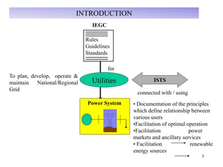
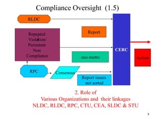
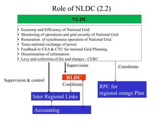
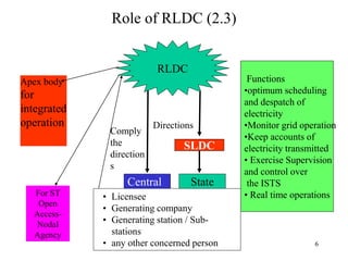
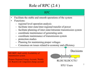
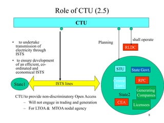
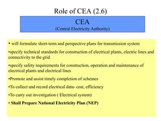
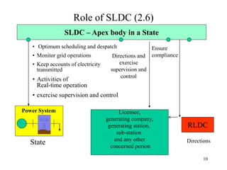
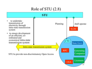
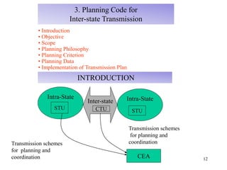
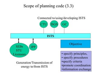
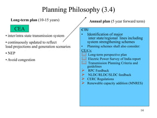
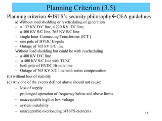
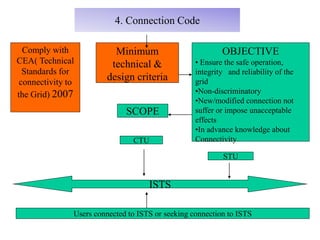
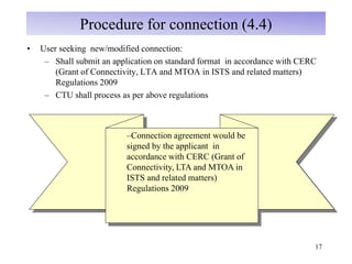
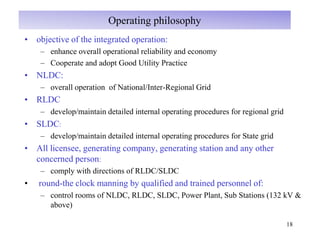
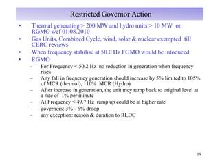
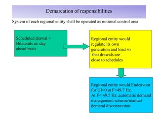
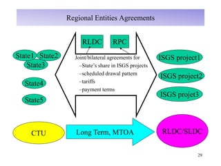
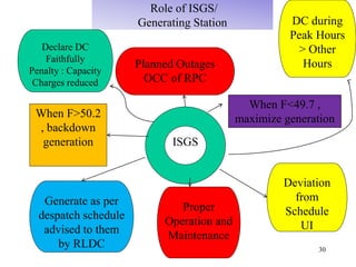
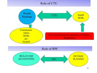
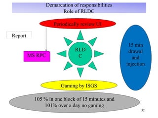
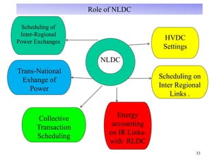
in
1
A POWER POINT PRESENTATION
ON
OVERVIEW OF GRID CODE TECHNICAL RECRUITMENTS
Submitted To :- Submitted By :-
2
Contents
1. General
2. Role of various organizations and their linkages
3. Planning code for Inter State Transmission
4. Connection Code
5. Operating Code
6. Scheduling and Dispatch Code
7. Miscellaneous
3
INTRODUCTION
To plan, develop, operate &
maintain National/Regional
Grid
Power System • Documentation of the principles
which define relationship between
various users
•Facilitation of optimal operation
•Facilitation power
markets and ancillary services
• Facilitation renewable
energy sources
IEGC
Rules
Guidelines
Standards
Utilities
connected with / using
for
ISTS
4
Compliance Oversight (1.5)
CERC
Repeated
Violation/
Persistent
Non
Compliance
RLDC
Report
RPC Consensus
Report issues
not sorted
suo-motto Action
2. Role of
Various Organizations and their linkages
NLDC, RLDC, RPC, CTU, CEA, SLDC & STU
Role of NLDC (2.2)
RLDC
Inter Regional Links
Supervision
• Economy and Efficiency of National Grid
• Monitoring of operations and grid security of National Grid
• Restoration of synchronous operation of National Grid
• Trans-national exchange of power
• Feedback to CEA & CTU for national Grid Planning
• Dissemination of information
• Levy and collection of fee and charges - CERC
• Disse
NLDC
Supervision & control
RPC for
regional outage Plan
Coordinate
Coordinate
Accounting
6
Role of RLDC (2.3)
Functions
•optimum scheduling
and despatch of
electricity
•Monitor grid operation
•Keep accounts of
electricity transmitted
• Exercise Supervision
and control over
the ISTS
• Real time operations• Licensee
• Generating company
• Generating station / Sub-
stations
• any other concerned person
SLDC
Central State
Directions
Comply
the
direction
s
Apex body
for
integrated
operation
For ST
Open
Access-
Nodal
Agency
RLDC
7
Role of RPC (2.4 )
• Facilitate the stable and smooth operations of the system
• Functions:
– regional level operation analysis
– facilitate inter-state/inter-regional transfer of power
– facilitate planning of inter-state/intrastate transmission system
– coordinate maintenance of generating units
– coordinate maintenance of transmission system
– protection studies
– Planning for maintaining proper voltages
– Consensus on issues related to economy and efficiency
RPC
RLDC/SLDC/CTU/
STU/ Users
Decisions
MS SRPC shall certify Availability of
transmission system
Prepare Regional Energy Account, Weekly
UI, Reactive & Congestion charge account
8
Role of CTU (2.5)
• to undertake
transmission of
electricity through
ISTS
• to ensure development
of an efficient, co-
ordinated and
economical ISTS
CTU
RLDC
shall operate
ISTS lines
CTU/to provide non-discriminatory Open Access
– Will not engage in trading and generation
– For LTOA & MTOA nodal agency
Planning
STU
Central
Govt.
State2
State1
State Govt.
Generating
Companies
CEA
RPC
Licensees
9
Role of CEA (2.6)
CEA
(Central Electricity Authority)
• will formulate short-term and perspective plans for transmission system
•specify technical standards for construction of electrical plants, electric lines and
connectivity to the grid
•specify safety requirements for construction, operation and maintenance of
electrical plants and electrical lines
•Promote and assist timely completion of schemes
•To collect and record electrical data- cost, efficiency
•To carry out investigation ( Electrical system)
• Shall Prepare National Electricity Plan (NEP)
10
Role of SLDC (2.6)
SLDC – Apex body in a State
Power System
State
• Optimum scheduling and despatch
• Monitor grid operations
• Keep accounts of electricity
transmitted
• Activities of
Real-time operation
• exercise supervision and control
RLDC
Directions
Ensure
complianceDirections and
exercise
supervision and
control
Licensee,
generating company,
generating station,
sub-station
and any other
concerned person
11
Role of STU (2.8)
• to undertake
transmission of
electricity through
intra-state transmission
system
• to ensure development
of an efficient, co-
ordinated and
economical intra-state
transmission system
STU
SLDC
shall operate
Intra-state transmission system
STU/to provide non-discriminatory Open Access
Planning
CTU
State Govt.
Generating
Companies
CEA
RPC
Licensees
12
INTRODUCTION
Intra-State
Inter-state
CEA
Intra-State
STU CTU
Transmission schemes
for planning and
coordination
STU
Transmission schemes
for planning and
coordination
3. Planning Code for
Inter-state Transmission
• Introduction
• Objective
• Scope
• Planning Philosophy
• Planning Criterion
• Planning Data
• Implementation of Transmission Plan
13
Scope of planning code (3.3)
ISTS
SEBs
STU
Licensees
ISGS GC
IPP
CTU
Generation/Transmission of
energy to/from ISTS
Connected to/using/developing ISTS
• specify principles,
• specify procedures
•specify criteria
•promote coordination
•information exchange
Objective
14
Planning Philosophy (3.4)
CTU
• Identification of major
inter state/regional lines including
system strengthening schemes
• Planning schemes shall also consider:
CEA’s:
 Long-term perspective plan
 Electric Power Survey of India report
 Transmission Planning Criteria and
guidelines
 RPC Feedback
 NLDC/RLDC/SLDC feedback
 CERC Regulations
 Renewable capacity addition (MNRES)
Annual plan (5 year forward term)
CEA
Long-term plan (10-15 years)
• inter/intra state transmission system
• continuously updated to reflect
load projections and generation scenarios
• NEP
• Avoid congestion
15
Planning Criterion (3.5)
Planning criterion ISTS’s security philosophyCEA guidelines
a) Without load shedding or rescheduling of generation
– a 132 KV D/C line, a 220 KV /DC line,
– a 400 KV S/C line, 765 KV S/C line
– single Inter-Connecting Transformer (ICT )
– one pole of HVDC Bi-pole
– Outage of 765 kV S/C line
Without load shedding but could be with rescheduling
– a 400 KV D/C line
– a 400 KV S/C line with TCSC
– both pole of HVDC Bi-pole line
– Outage of 765 KV S/C line with series compensation
(b) without loss of stability
(c) Any one of the events defined above should not cause:
– loss of supply
– prolonged operation of frequency below and above limits
– unacceptable high or low voltage
– system instability
– unacceptable overloading of ISTS elements
4. Connection Code
Minimum
technical &
design criteria
OBJECTIVE
• Ensure the safe operation,
integrity and reliability of the
grid
•Non-discriminatory
•New/modified connection not
suffer or impose unacceptable
effects
•In advance knowledge about
Connectivity
ISTS
SCOPE
CTU
STU
Users connected to ISTS or seeking connection to ISTS
Comply with
CEA( Technical
Standards for
connectivity to
the Grid) 2007
17
Procedure for connection (4.4)
• User seeking new/modified connection:
– Shall submit an application on standard format in accordance with CERC
(Grant of Connectivity, LTA and MTOA in ISTS and related matters)
Regulations 2009
– CTU shall process as per above regulations
–Connection agreement would be
signed by the applicant in
accordance with CERC (Grant of
Connectivity, LTA and MTOA in
ISTS and related matters)
Regulations 2009
18
Operating philosophy
• objective of the integrated operation:
– enhance overall operational reliability and economy
– Cooperate and adopt Good Utility Practice
• NLDC:
– overall operation of National/Inter-Regional Grid
• RLDC
– develop/maintain detailed internal operating procedures for regional grid
• SLDC:
– develop/maintain detailed internal operating procedures for State grid
• All licensee, generating company, generating station and any other
concerned person:
– comply with directions of RLDC/SLDC
• round-the clock manning by qualified and trained personnel of:
– control rooms of NLDC, RLDC, SLDC, Power Plant, Sub Stations (132 kV &
above)
19
Restricted Governor Action
• Thermal generating > 200 MW and hydro units > 10 MW on
RGMO wef 01.08.2010
• Gas Units, Combined Cycle, wind, solar & nuclear exempted till
CERC reviews
• When frequency stabilise at 50.0 Hz FGMO would be intoduced
• RGMO
– For Frequency < 50.2 Hz no reduction in generation when frequency
rises
– Any fall in frequency generation should increase by 5% limited to 105%
of MCR (thermal), 110% MCR (Hydro)
– After increase in generation, the unit mey ramp back to original level at
a rate of 1% per minute
– At Frequency < 49.7 Hz ramp up could be at higher rate
– governors: 3% - 6% droop
– any exception: reason & duration to RLDC
20
DEMAND ESTIMATION FOR
OPERARTIONAL PURPOSES
on-line estimation
for daily operationa
l use
historical data
and weather forecast
Daily
/Weekly
/Monthly
Demand Estimation –
Active and reactive
power
By 01.01.2011 – online estimation of
demand for each 15 min block
Inform to
RLDC/
RPCWind
Energy
Forecast
ATC/
TTC
21
Outage Planning Process
MarJanNov next financial year
proposed outage programs by all concerned (30th Nov)
Dec
draft outage program by RPC Secretariat (31st Dec)
final outage programme by (31st Jan)
Feb
Review by RPC Secretariat:
adjustments made wherever
found to be necessary in
coordination with all parties
concerned
monthly review quarterly review
22
Recovery Procedures (5.8)
Detailed plans/procedures for
restoration of partial/total blackout
regional grid
consultations
RLDC
Concerned
Constituents
RPC secretariat
develops
reviewed/updated annually
Detailed plans/procedures for
restoration of partial/total blackout
develop
reviewed/updated annually
• Mock trials once
every 6 months
•DG sets to be tested
on weekly basis-
quarterly report to be
sent to RLDC
23
Reporting Procedure
RLDC
Users/STU/
CTU/SLDC
written report
of events
weekly written report
of events
• Form of written reports:
NLDC
i) Time and date vi) Duration of interruption
ii) Location vii) Recording System informations
iii) Plant or equipment directly
involved
viii) Sequence of trippings with time
iv) Description and cause of event ix) Remedial Measures
v) Antecedent Condition
24
6. Scheduling & Despatch Code
a) demarcation of responsibilities
b) procedure for scheduling & despatch
c) Reactive power and voltage control mechanism
d) complementary commercial mechanism (Annexure-I)
System Security Aspects
Voltage- (kV rms)
Nominal Maximum Minimum
765 800 728
400 420 380
220 245 198
132 145 122
110 121 99
66 72 60
33 36 30
OBJECTIVE
•Procedure for submission of Capability declaration
•Procedure for submission of requistion/ drawal schedule by regional entities
•Real time despatch/drawal instructions
•Rescheduling
• Commercial arrangement for UI/Reactive
• Scheduling of wind/solar on 3 hourly basis
•Appropriate Metering
Discoms
SCOPE
Power
Exchanges
ISGS
SEBs/STUs Other
concerned
Wind/Solar
generators
NLDC RLDC SLDC
26
Demarcation of responsibilities
Role of RLDC
RLD
C
Scheduling of CGS (Except where
full share is allocated to host state)
Scheduling of UMPP
Schedul
ing of
GS
connect
ed to
ISTS
Scheduling
of GS
connected
both to
ISTS and
state grid
and home
state is less
then 50%
27
Demarcation of responsibilities
SLDC
SLDC
Permitting
Open Access
Regulating
net drawal
Scheduling and
despatching
Scheduling
drawal from
ISGS
Demand
Regulation
6.4.8 Demand
Estimation in
coordination with
STU/Discoms
28
Demarcation of responsibilities
System of each regional entity shall be operated as notional control area
Scheduled drawal +
Bilaterals on day
ahead basis
Regional entity would
regulate its own
generation and load so
that drawals are
close to schedules
Regional entity would Endeavour
for UI=0 at F<49.7 Hz.
At F< 49.5 Hz ,automatic demand
management scheme/manual
demand disconnection
29
Regional Entities Agreements
ISGS project2
Joint/bilateral agreements for
–State’s share in ISGS projects
–scheduled drawal pattern
–tariffs
–payment terms
ISGS project1
ISGS projet3
State3
State4
State5
State2State1
RLDC RPC
CTU Long Term, MTOA RLDC/SLDC
30
Role of ISGS/
Generating Station
ISGS
Generate as per
despatch schedule
advised to them
by RLDC
Deviation
from
Schedule
UI
Proper
Operation and
Maintenance
When F>50.2
, backdown
generation
When F<49.7 ,
maximize generation
Planned Outages
OCC of RPC
DC during
Peak Hours
> Other
Hours
Declare DC
Faithfully
Penalty : Capacity
Charges reduced
31
Role of CTU
CTU Install
SEMs
CEA (Installation and operation of Meters )
Regulations
Weekly
Readings
Constituents
where
SEMs
are
located
Role of RPC
REA,UI,VAR
ACCOUNTING RPC
OUTAGE
PLANING
32
Demarcation of responsibilities
Role of RLDC
RLD
C
Periodically review UI
Gaming by ISGS
15 min
drawal
and
injection
MS RPC
Report
105 % in one block of 15 minutes and
101% over a day no gaming
33
Role of NLDC
NLDC
Trans-National
Exhange of
Power
Scheduling on
Inter Regional
Links .
Energy
accounting
on IR Links-
with RLDC
HVDC
Settings
Scheduling of
Inter-Regional
Power Exchanges
Collective
Transaction
Scheduling
34
Reactive Power & Voltage Control (6.6)
• VAR Charges under Low
Voltage
• VAR Charges under High
voltage
Beneficiary1
Voltage: < 97%
Pool Account
VAR charges
EHV grid
Beneficiary2
Q Q
Beneficiary1
Voltage: > 103%
Pool Account
VAR charges
EHV grid
Beneficiary2
Q Q
35
VAR charges settlement
• No VAR charges for its own lines emanating directly from ISGS
• VAR charges at the nominal paise/KVArh rate as may be specified by
CERC and will be between beneficiaries and POOL (Present rate is
10.0 p/kvarh with escalation of 0.5 p/kvarh every year)
• RLDC may direct Regional entity to curtail VAR drawal/injection for
safety and security of grid or safety of equipment
• Beneficiaries to minimise injection/drawal of VAR if voltage goes
beyond + 5%.
• ICT taps may changed as per regional entity request to RLDC
• Tap changing (400/220 kV)and switching in/out of line reactors
(400kV) shall be carried out as per RLDC instruction.
36
Capacity charge + Energy charge
ISGS
beneficiary1
beneficiary2
UI
Capacity charge + Energy charge
UI
Generation Cost
UI
Settlement
System
UI
Full
reimbursement
for generation as
per the
generation
schedule
37
Weekly bills & penalty
RLDC
Constituents
UI
Settlement
System
Pool
Account
UI bills UI payment
VAR payment
• payment within 10 days from date of billing
• simple interest @ 0.04% per day to constituent for delayed payment
beyond 12 days.
RPC VAR bills
monthly payment
status
CERCpayment defaults
38
Regional Energy Accounting
Sun
15-minute block
SEM readings for a week
RLDC
Constituents
Weekly raw
SEM data
Weekly
UI and
VAR
Account
ISTS
Connections
Mon
Tue
Wed
Thu
Fri
Sat
Sun
Mon
Tue
Wed
Thu
Fri
Sat
Sun
Mon
Tue


Monthly (6th):
REA
RLDC to tabulate UI account and REA in RPC’s CC
meeting on a quarterrly basis for audit by the later.

Grid code

  • 1.
    in 1 A POWER POINTPRESENTATION ON OVERVIEW OF GRID CODE TECHNICAL RECRUITMENTS Submitted To :- Submitted By :-
  • 2.
    2 Contents 1. General 2. Roleof various organizations and their linkages 3. Planning code for Inter State Transmission 4. Connection Code 5. Operating Code 6. Scheduling and Dispatch Code 7. Miscellaneous
  • 3.
    3 INTRODUCTION To plan, develop,operate & maintain National/Regional Grid Power System • Documentation of the principles which define relationship between various users •Facilitation of optimal operation •Facilitation power markets and ancillary services • Facilitation renewable energy sources IEGC Rules Guidelines Standards Utilities connected with / using for ISTS
  • 4.
    4 Compliance Oversight (1.5) CERC Repeated Violation/ Persistent Non Compliance RLDC Report RPCConsensus Report issues not sorted suo-motto Action 2. Role of Various Organizations and their linkages NLDC, RLDC, RPC, CTU, CEA, SLDC & STU
  • 5.
    Role of NLDC(2.2) RLDC Inter Regional Links Supervision • Economy and Efficiency of National Grid • Monitoring of operations and grid security of National Grid • Restoration of synchronous operation of National Grid • Trans-national exchange of power • Feedback to CEA & CTU for national Grid Planning • Dissemination of information • Levy and collection of fee and charges - CERC • Disse NLDC Supervision & control RPC for regional outage Plan Coordinate Coordinate Accounting
  • 6.
    6 Role of RLDC(2.3) Functions •optimum scheduling and despatch of electricity •Monitor grid operation •Keep accounts of electricity transmitted • Exercise Supervision and control over the ISTS • Real time operations• Licensee • Generating company • Generating station / Sub- stations • any other concerned person SLDC Central State Directions Comply the direction s Apex body for integrated operation For ST Open Access- Nodal Agency RLDC
  • 7.
    7 Role of RPC(2.4 ) • Facilitate the stable and smooth operations of the system • Functions: – regional level operation analysis – facilitate inter-state/inter-regional transfer of power – facilitate planning of inter-state/intrastate transmission system – coordinate maintenance of generating units – coordinate maintenance of transmission system – protection studies – Planning for maintaining proper voltages – Consensus on issues related to economy and efficiency RPC RLDC/SLDC/CTU/ STU/ Users Decisions MS SRPC shall certify Availability of transmission system Prepare Regional Energy Account, Weekly UI, Reactive & Congestion charge account
  • 8.
    8 Role of CTU(2.5) • to undertake transmission of electricity through ISTS • to ensure development of an efficient, co- ordinated and economical ISTS CTU RLDC shall operate ISTS lines CTU/to provide non-discriminatory Open Access – Will not engage in trading and generation – For LTOA & MTOA nodal agency Planning STU Central Govt. State2 State1 State Govt. Generating Companies CEA RPC Licensees
  • 9.
    9 Role of CEA(2.6) CEA (Central Electricity Authority) • will formulate short-term and perspective plans for transmission system •specify technical standards for construction of electrical plants, electric lines and connectivity to the grid •specify safety requirements for construction, operation and maintenance of electrical plants and electrical lines •Promote and assist timely completion of schemes •To collect and record electrical data- cost, efficiency •To carry out investigation ( Electrical system) • Shall Prepare National Electricity Plan (NEP)
  • 10.
    10 Role of SLDC(2.6) SLDC – Apex body in a State Power System State • Optimum scheduling and despatch • Monitor grid operations • Keep accounts of electricity transmitted • Activities of Real-time operation • exercise supervision and control RLDC Directions Ensure complianceDirections and exercise supervision and control Licensee, generating company, generating station, sub-station and any other concerned person
  • 11.
    11 Role of STU(2.8) • to undertake transmission of electricity through intra-state transmission system • to ensure development of an efficient, co- ordinated and economical intra-state transmission system STU SLDC shall operate Intra-state transmission system STU/to provide non-discriminatory Open Access Planning CTU State Govt. Generating Companies CEA RPC Licensees
  • 12.
    12 INTRODUCTION Intra-State Inter-state CEA Intra-State STU CTU Transmission schemes forplanning and coordination STU Transmission schemes for planning and coordination 3. Planning Code for Inter-state Transmission • Introduction • Objective • Scope • Planning Philosophy • Planning Criterion • Planning Data • Implementation of Transmission Plan
  • 13.
    13 Scope of planningcode (3.3) ISTS SEBs STU Licensees ISGS GC IPP CTU Generation/Transmission of energy to/from ISTS Connected to/using/developing ISTS • specify principles, • specify procedures •specify criteria •promote coordination •information exchange Objective
  • 14.
    14 Planning Philosophy (3.4) CTU •Identification of major inter state/regional lines including system strengthening schemes • Planning schemes shall also consider: CEA’s:  Long-term perspective plan  Electric Power Survey of India report  Transmission Planning Criteria and guidelines  RPC Feedback  NLDC/RLDC/SLDC feedback  CERC Regulations  Renewable capacity addition (MNRES) Annual plan (5 year forward term) CEA Long-term plan (10-15 years) • inter/intra state transmission system • continuously updated to reflect load projections and generation scenarios • NEP • Avoid congestion
  • 15.
    15 Planning Criterion (3.5) Planningcriterion ISTS’s security philosophyCEA guidelines a) Without load shedding or rescheduling of generation – a 132 KV D/C line, a 220 KV /DC line, – a 400 KV S/C line, 765 KV S/C line – single Inter-Connecting Transformer (ICT ) – one pole of HVDC Bi-pole – Outage of 765 kV S/C line Without load shedding but could be with rescheduling – a 400 KV D/C line – a 400 KV S/C line with TCSC – both pole of HVDC Bi-pole line – Outage of 765 KV S/C line with series compensation (b) without loss of stability (c) Any one of the events defined above should not cause: – loss of supply – prolonged operation of frequency below and above limits – unacceptable high or low voltage – system instability – unacceptable overloading of ISTS elements
  • 16.
    4. Connection Code Minimum technical& design criteria OBJECTIVE • Ensure the safe operation, integrity and reliability of the grid •Non-discriminatory •New/modified connection not suffer or impose unacceptable effects •In advance knowledge about Connectivity ISTS SCOPE CTU STU Users connected to ISTS or seeking connection to ISTS Comply with CEA( Technical Standards for connectivity to the Grid) 2007
  • 17.
    17 Procedure for connection(4.4) • User seeking new/modified connection: – Shall submit an application on standard format in accordance with CERC (Grant of Connectivity, LTA and MTOA in ISTS and related matters) Regulations 2009 – CTU shall process as per above regulations –Connection agreement would be signed by the applicant in accordance with CERC (Grant of Connectivity, LTA and MTOA in ISTS and related matters) Regulations 2009
  • 18.
    18 Operating philosophy • objectiveof the integrated operation: – enhance overall operational reliability and economy – Cooperate and adopt Good Utility Practice • NLDC: – overall operation of National/Inter-Regional Grid • RLDC – develop/maintain detailed internal operating procedures for regional grid • SLDC: – develop/maintain detailed internal operating procedures for State grid • All licensee, generating company, generating station and any other concerned person: – comply with directions of RLDC/SLDC • round-the clock manning by qualified and trained personnel of: – control rooms of NLDC, RLDC, SLDC, Power Plant, Sub Stations (132 kV & above)
  • 19.
    19 Restricted Governor Action •Thermal generating > 200 MW and hydro units > 10 MW on RGMO wef 01.08.2010 • Gas Units, Combined Cycle, wind, solar & nuclear exempted till CERC reviews • When frequency stabilise at 50.0 Hz FGMO would be intoduced • RGMO – For Frequency < 50.2 Hz no reduction in generation when frequency rises – Any fall in frequency generation should increase by 5% limited to 105% of MCR (thermal), 110% MCR (Hydro) – After increase in generation, the unit mey ramp back to original level at a rate of 1% per minute – At Frequency < 49.7 Hz ramp up could be at higher rate – governors: 3% - 6% droop – any exception: reason & duration to RLDC
  • 20.
    20 DEMAND ESTIMATION FOR OPERARTIONALPURPOSES on-line estimation for daily operationa l use historical data and weather forecast Daily /Weekly /Monthly Demand Estimation – Active and reactive power By 01.01.2011 – online estimation of demand for each 15 min block Inform to RLDC/ RPCWind Energy Forecast ATC/ TTC
  • 21.
    21 Outage Planning Process MarJanNovnext financial year proposed outage programs by all concerned (30th Nov) Dec draft outage program by RPC Secretariat (31st Dec) final outage programme by (31st Jan) Feb Review by RPC Secretariat: adjustments made wherever found to be necessary in coordination with all parties concerned monthly review quarterly review
  • 22.
    22 Recovery Procedures (5.8) Detailedplans/procedures for restoration of partial/total blackout regional grid consultations RLDC Concerned Constituents RPC secretariat develops reviewed/updated annually Detailed plans/procedures for restoration of partial/total blackout develop reviewed/updated annually • Mock trials once every 6 months •DG sets to be tested on weekly basis- quarterly report to be sent to RLDC
  • 23.
    23 Reporting Procedure RLDC Users/STU/ CTU/SLDC written report ofevents weekly written report of events • Form of written reports: NLDC i) Time and date vi) Duration of interruption ii) Location vii) Recording System informations iii) Plant or equipment directly involved viii) Sequence of trippings with time iv) Description and cause of event ix) Remedial Measures v) Antecedent Condition
  • 24.
    24 6. Scheduling &Despatch Code a) demarcation of responsibilities b) procedure for scheduling & despatch c) Reactive power and voltage control mechanism d) complementary commercial mechanism (Annexure-I) System Security Aspects Voltage- (kV rms) Nominal Maximum Minimum 765 800 728 400 420 380 220 245 198 132 145 122 110 121 99 66 72 60 33 36 30
  • 25.
    OBJECTIVE •Procedure for submissionof Capability declaration •Procedure for submission of requistion/ drawal schedule by regional entities •Real time despatch/drawal instructions •Rescheduling • Commercial arrangement for UI/Reactive • Scheduling of wind/solar on 3 hourly basis •Appropriate Metering Discoms SCOPE Power Exchanges ISGS SEBs/STUs Other concerned Wind/Solar generators NLDC RLDC SLDC
  • 26.
    26 Demarcation of responsibilities Roleof RLDC RLD C Scheduling of CGS (Except where full share is allocated to host state) Scheduling of UMPP Schedul ing of GS connect ed to ISTS Scheduling of GS connected both to ISTS and state grid and home state is less then 50%
  • 27.
    27 Demarcation of responsibilities SLDC SLDC Permitting OpenAccess Regulating net drawal Scheduling and despatching Scheduling drawal from ISGS Demand Regulation 6.4.8 Demand Estimation in coordination with STU/Discoms
  • 28.
    28 Demarcation of responsibilities Systemof each regional entity shall be operated as notional control area Scheduled drawal + Bilaterals on day ahead basis Regional entity would regulate its own generation and load so that drawals are close to schedules Regional entity would Endeavour for UI=0 at F<49.7 Hz. At F< 49.5 Hz ,automatic demand management scheme/manual demand disconnection
  • 29.
    29 Regional Entities Agreements ISGSproject2 Joint/bilateral agreements for –State’s share in ISGS projects –scheduled drawal pattern –tariffs –payment terms ISGS project1 ISGS projet3 State3 State4 State5 State2State1 RLDC RPC CTU Long Term, MTOA RLDC/SLDC
  • 30.
    30 Role of ISGS/ GeneratingStation ISGS Generate as per despatch schedule advised to them by RLDC Deviation from Schedule UI Proper Operation and Maintenance When F>50.2 , backdown generation When F<49.7 , maximize generation Planned Outages OCC of RPC DC during Peak Hours > Other Hours Declare DC Faithfully Penalty : Capacity Charges reduced
  • 31.
    31 Role of CTU CTUInstall SEMs CEA (Installation and operation of Meters ) Regulations Weekly Readings Constituents where SEMs are located Role of RPC REA,UI,VAR ACCOUNTING RPC OUTAGE PLANING
  • 32.
    32 Demarcation of responsibilities Roleof RLDC RLD C Periodically review UI Gaming by ISGS 15 min drawal and injection MS RPC Report 105 % in one block of 15 minutes and 101% over a day no gaming
  • 33.
    33 Role of NLDC NLDC Trans-National Exhangeof Power Scheduling on Inter Regional Links . Energy accounting on IR Links- with RLDC HVDC Settings Scheduling of Inter-Regional Power Exchanges Collective Transaction Scheduling
  • 34.
    34 Reactive Power &Voltage Control (6.6) • VAR Charges under Low Voltage • VAR Charges under High voltage Beneficiary1 Voltage: < 97% Pool Account VAR charges EHV grid Beneficiary2 Q Q Beneficiary1 Voltage: > 103% Pool Account VAR charges EHV grid Beneficiary2 Q Q
  • 35.
    35 VAR charges settlement •No VAR charges for its own lines emanating directly from ISGS • VAR charges at the nominal paise/KVArh rate as may be specified by CERC and will be between beneficiaries and POOL (Present rate is 10.0 p/kvarh with escalation of 0.5 p/kvarh every year) • RLDC may direct Regional entity to curtail VAR drawal/injection for safety and security of grid or safety of equipment • Beneficiaries to minimise injection/drawal of VAR if voltage goes beyond + 5%. • ICT taps may changed as per regional entity request to RLDC • Tap changing (400/220 kV)and switching in/out of line reactors (400kV) shall be carried out as per RLDC instruction.
  • 36.
    36 Capacity charge +Energy charge ISGS beneficiary1 beneficiary2 UI Capacity charge + Energy charge UI Generation Cost UI Settlement System UI Full reimbursement for generation as per the generation schedule
  • 37.
    37 Weekly bills &penalty RLDC Constituents UI Settlement System Pool Account UI bills UI payment VAR payment • payment within 10 days from date of billing • simple interest @ 0.04% per day to constituent for delayed payment beyond 12 days. RPC VAR bills monthly payment status CERCpayment defaults
  • 38.
    38 Regional Energy Accounting Sun 15-minuteblock SEM readings for a week RLDC Constituents Weekly raw SEM data Weekly UI and VAR Account ISTS Connections Mon Tue Wed Thu Fri Sat Sun Mon Tue Wed Thu Fri Sat Sun Mon Tue   Monthly (6th): REA RLDC to tabulate UI account and REA in RPC’s CC meeting on a quarterrly basis for audit by the later.