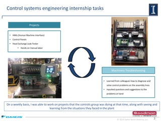
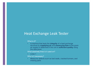
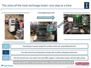
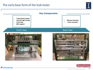
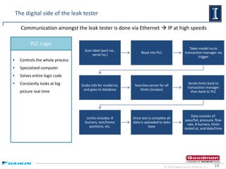
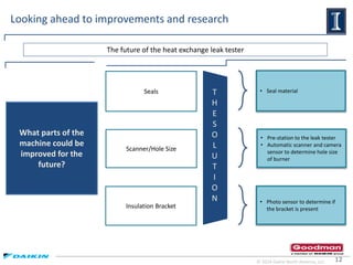
Summer Internship 2016
Goodman
Manufacturing
Friday August 5th 2016
Final Presentation
Overview
Jeremy French
• Education: University of Illinois Urbana-Champaign
• Expected Graduation: May 2018
• B.S. in Industrial and Systems Engineering
• Manufacturing Department- Ray Pitts
• Control Systems- Randy Spaulding
• Controls Engineering Intern
3
On a weekly basis, I was able to work on projects that the controls group was doing at that time, along with seeing and
learning from the situations they faced in the plant
Control systems engineering internship tasks
• HMIs (Human Machine Interface)
• Control Panels
• Heat Exchange Leak Tester
• Hands on manual labor
Projects
• Learned from colleagues how to diagnose and
solve control problems on the assembly lines
• Inputted questions and suggestions to the
problems at hand
Machinery Troubleshooting
© 2014 Daikin North America, LLC
4
Human Machine Interface (HMIs)
Physical Construction
• 80/20 extruded aluminum, bare bone
Key Points
Internal Makeup
• E-stop, Ethernet, RTA module
Mainly used for all testers on Lines 1 and 7
© 2014 Daikin North America, LLC
5
• Neat and clean
• Labels and color code standard
• DC vs. AC
• Terminate wires
Control panels from start to finish and everything in between
Concise statements
with no fluff
Circuit Schematics The Layout
© 2014 Daikin North America, LLC
Heat Exchange Leak Tester
What is it?
• A machine that tests the integrity of a heat exchange
structure by supplying air and measuring flow at the given
air supply to determine if the unit is sufficient quality using
the data given
What assembly lines is it used on?
• Lines 1
Why is it necessary?
• Measures defects such as bad seals, cracked burners, and
missing parts
7
The story of the heat exchange tester: one step at a time
1
2
3
Everything is manual, except for numatics which are controlled by the PLC
The next version has 4 drop down clamps with no other clamping mechanisms
The final version has a rear stop, front stop, 80% support, 7 drop down clamps, left and right clamps
From Beginning to End
© 2014 Daikin North America, LLC
As the machine was updated, the test became more efficient and there were less system leaks
8
The early base form of the leak tester
• 7 drop down clamps
• Left and right clamps
• Front stop
• 80% support
• Shannon Precision
• Linear actuators
Front View Back View
Key Components
© 2014 Daikin North America, LLC
9
The physical components of the leak tester
Linear Control Modules
• Power Control (Pecans)
• Control actuators
Numatics
• Control numatics-actuate
clamps
• Test numatics-actuate tests
• Test, field, solenoid valves
© 2014 Daikin North America, LLC
Control Panel
• Heart of machine
• Controls clamping,
numatics, and all power
• Receives limits
• Collects and sends data
H.M.I.
• Interface with operator
• Master start, E-stop
• Displays test data
10
The digital side of the leak tester
• Controls the whole process
• Specialized computer
• Solves entire logic code
• Constantly looks at big
picture real time
PLC Logic
© 2014 Daikin North America, LLC
Communication amongst the leak tester is done via Ethernet  IP at high speeds
Scan label (part no.,
serial no.)
Read into PLC
Takes model no.to
transaction manager via
trigger
Grabs info for model no.
and goes to database
Searches server for all
limits (recipes)
Sends limits back to
transaction manager
then back to PLC
Limits includes: #
burners, test/home
positions, etc.
Once test is complete all
data is uploaded to data
base
Data consists of:
pass/fail, pressure, flow
rate, # burners, limits
tested at, and date/time
11
The end result and functionality of the leak tester
© 2014 Daikin North America, LLC
Model is selected in
manual or auto mode
Scan specific part
Part is loaded into test
position
User starts test by
placing fingers on the 2
hand control
Machine clamps part
into position
Test begins
Unit is filled with air
from both test and field
valves for a period of
time
Field valve closes, test
valve remains open:
pressure check above .5
in of water column
Test proceeds to adjust
air to 1 in of water
column +/- .5 and that
flow is below the
maximum limit
Machine checks that
flow and pressure are
just right
Send data (model no.,
pressure, flow, date and
time) to database
Machine prints label
and unclamps part
Operator removes part
and places label on part
Cycle repeats again
12
Looking ahead to improvements and research
Seals
Scanner/Hole Size
Insulation Bracket
• Seal material
• Pre-station to the leak tester
• Automatic scanner and camera
sensor to determine hole size
of burner
• Photo sensor to determine if
the bracket is present
The future of the heat exchange leak tester
What parts of the
machine could be
improved for the
future?
© 2014 Daikin North America, LLC
T
H
E
S
O
L
U
T
I
O
N
Special Thanks
• Human Resources
• Blake Miller
• Manufacturing Department
• Ray Pitts-Supervisor
• Controls Engineering Group
• Randy Spaulding-Manager
• Mike Anders
• Don Fenton
• Shanthan Gambhir
• David Haynes

Goodman Final Presentation_French_Jeremy

  • 1.
    Summer Internship 2016 Goodman Manufacturing FridayAugust 5th 2016 Final Presentation
  • 2.
    Overview Jeremy French • Education:University of Illinois Urbana-Champaign • Expected Graduation: May 2018 • B.S. in Industrial and Systems Engineering • Manufacturing Department- Ray Pitts • Control Systems- Randy Spaulding • Controls Engineering Intern
  • 3.
    3 On a weeklybasis, I was able to work on projects that the controls group was doing at that time, along with seeing and learning from the situations they faced in the plant Control systems engineering internship tasks • HMIs (Human Machine Interface) • Control Panels • Heat Exchange Leak Tester • Hands on manual labor Projects • Learned from colleagues how to diagnose and solve control problems on the assembly lines • Inputted questions and suggestions to the problems at hand Machinery Troubleshooting © 2014 Daikin North America, LLC
  • 4.
    4 Human Machine Interface(HMIs) Physical Construction • 80/20 extruded aluminum, bare bone Key Points Internal Makeup • E-stop, Ethernet, RTA module Mainly used for all testers on Lines 1 and 7 © 2014 Daikin North America, LLC
  • 5.
    5 • Neat andclean • Labels and color code standard • DC vs. AC • Terminate wires Control panels from start to finish and everything in between Concise statements with no fluff Circuit Schematics The Layout © 2014 Daikin North America, LLC
  • 6.
    Heat Exchange LeakTester What is it? • A machine that tests the integrity of a heat exchange structure by supplying air and measuring flow at the given air supply to determine if the unit is sufficient quality using the data given What assembly lines is it used on? • Lines 1 Why is it necessary? • Measures defects such as bad seals, cracked burners, and missing parts
  • 7.
    7 The story ofthe heat exchange tester: one step at a time 1 2 3 Everything is manual, except for numatics which are controlled by the PLC The next version has 4 drop down clamps with no other clamping mechanisms The final version has a rear stop, front stop, 80% support, 7 drop down clamps, left and right clamps From Beginning to End © 2014 Daikin North America, LLC As the machine was updated, the test became more efficient and there were less system leaks
  • 8.
    8 The early baseform of the leak tester • 7 drop down clamps • Left and right clamps • Front stop • 80% support • Shannon Precision • Linear actuators Front View Back View Key Components © 2014 Daikin North America, LLC
  • 9.
    9 The physical componentsof the leak tester Linear Control Modules • Power Control (Pecans) • Control actuators Numatics • Control numatics-actuate clamps • Test numatics-actuate tests • Test, field, solenoid valves © 2014 Daikin North America, LLC Control Panel • Heart of machine • Controls clamping, numatics, and all power • Receives limits • Collects and sends data H.M.I. • Interface with operator • Master start, E-stop • Displays test data
  • 10.
    10 The digital sideof the leak tester • Controls the whole process • Specialized computer • Solves entire logic code • Constantly looks at big picture real time PLC Logic © 2014 Daikin North America, LLC Communication amongst the leak tester is done via Ethernet  IP at high speeds Scan label (part no., serial no.) Read into PLC Takes model no.to transaction manager via trigger Grabs info for model no. and goes to database Searches server for all limits (recipes) Sends limits back to transaction manager then back to PLC Limits includes: # burners, test/home positions, etc. Once test is complete all data is uploaded to data base Data consists of: pass/fail, pressure, flow rate, # burners, limits tested at, and date/time
  • 11.
    11 The end resultand functionality of the leak tester © 2014 Daikin North America, LLC Model is selected in manual or auto mode Scan specific part Part is loaded into test position User starts test by placing fingers on the 2 hand control Machine clamps part into position Test begins Unit is filled with air from both test and field valves for a period of time Field valve closes, test valve remains open: pressure check above .5 in of water column Test proceeds to adjust air to 1 in of water column +/- .5 and that flow is below the maximum limit Machine checks that flow and pressure are just right Send data (model no., pressure, flow, date and time) to database Machine prints label and unclamps part Operator removes part and places label on part Cycle repeats again
  • 12.
    12 Looking ahead toimprovements and research Seals Scanner/Hole Size Insulation Bracket • Seal material • Pre-station to the leak tester • Automatic scanner and camera sensor to determine hole size of burner • Photo sensor to determine if the bracket is present The future of the heat exchange leak tester What parts of the machine could be improved for the future? © 2014 Daikin North America, LLC T H E S O L U T I O N
  • 13.
    Special Thanks • HumanResources • Blake Miller • Manufacturing Department • Ray Pitts-Supervisor • Controls Engineering Group • Randy Spaulding-Manager • Mike Anders • Don Fenton • Shanthan Gambhir • David Haynes