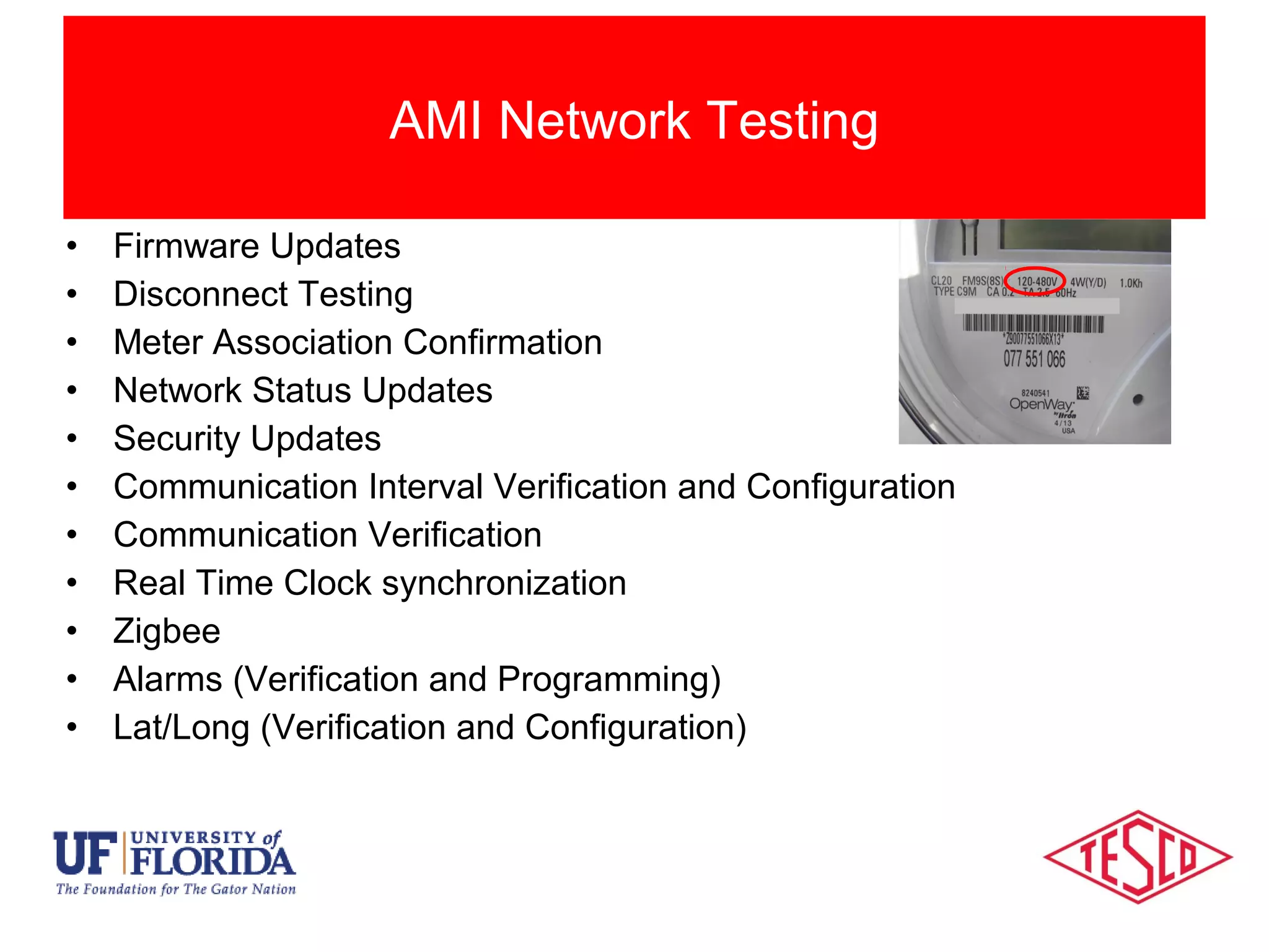
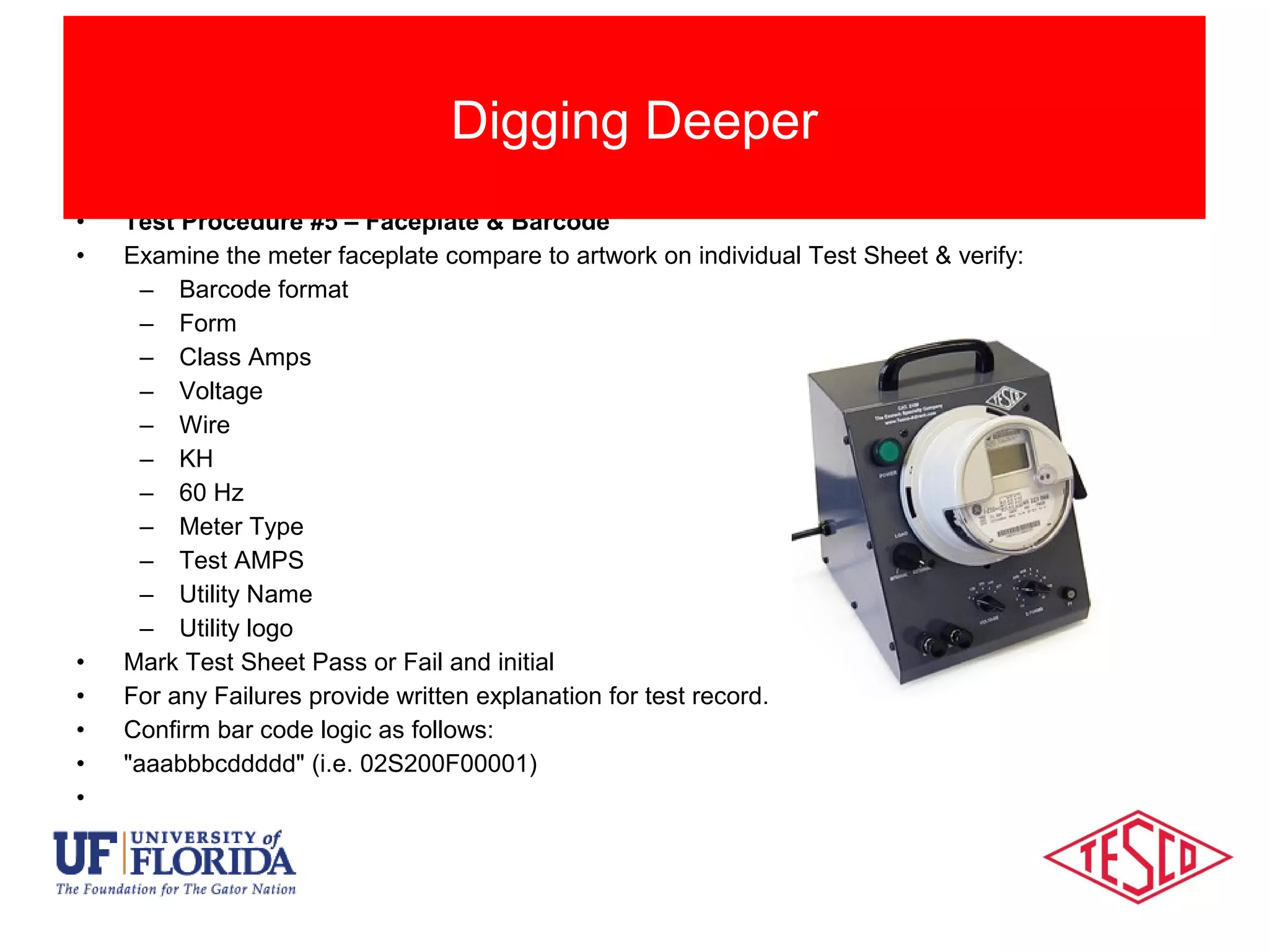
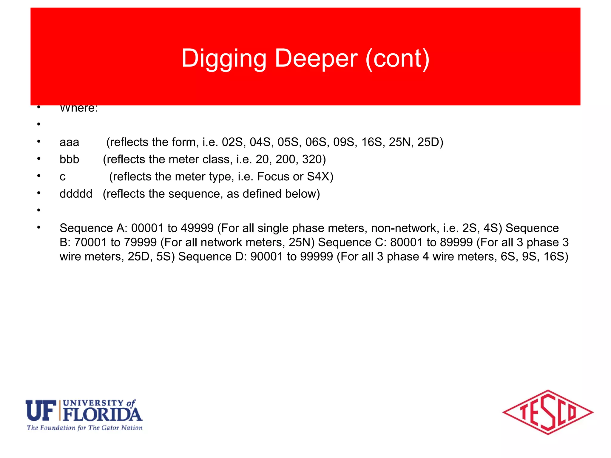
10/02/2012 Slide 1
AMI Meter Certification
Before, During & After Deployment
Notes from the Shop
Prepared by Tom Lawton, TESCO
for the SEMA Conference 2016
Session Objectives
• Initial Certification testing and First Article Testing
• Developing functional testing from initial Certification
protocols
• The need for continued Certification Testing on a regular
basis
• Protocols and frequency for certification testing during
and after deployment
Session Objectives
Session Objectives
Managing change and minimizing risk
Types of Meter Testing
• New meters have many tests specified in ANSI C12.1 and
C12.20, typically performed by the meter vendors.
• These tests only involve what has been traditionally
considered “the meter”
• With AMI meters all meter functionality must be considered
and tested, even where no standard test exists
• Each Utility must develop their own Certification Test protocol
– The First Article Test can be a subset of this Certification
Test or repeat everything in the Certification Test.
Meter Certification
Impact of AMI Devices
• Certification Testing can cover a wide variety of
sins. Initially the meter vendor selected provides
a 2S meter or another relatively common meter
and an entire battery of tests is performed to
“Certify” this meter for this application.
• First Article Testing (FAT) confirms that the first
meter of each type that is delivered meets all
requirements quoted in a satisfactory manner.
Certification vs. First Article Testing
Categories Of Meter Testing
• First Article Testing (cont)
– The FAT protocols may be a subset of the initial
Certification testing or may have all of the same
protocols.
• Certification Testing (cont)
– Once FAT is completed the Certification testing is not
complete. Certification testing begins again with the
first change to the meter’s being delivered. The
changes could be hardware, software, firmware or
even settings. This testing is typically a subset of FAT
protocols.
Traditional Categories of Meter Testing
Categories Of Meter Testing
• Whenever we are aware of a significant design
change or firmware change to the meter
– What is “significant”? This is up to the user.
Significant should be defined as a potential risk.
Potential can be defined as something more than an
“unlikely or remote possibility”.
• On a time based frequency (e.g. once per year) if
there is a stream of small changes and no epic
changes over a short period of time.
– This is not set in stone but is simply a recommended
practice.
How frequently should Certification testing be repeated?
• Inspection
• Error Reporting/Clearing
• Clear/Reset
• Meter Reprogramming
• Program Verification
• Disconnect Testing
• Firmware Updates
• Security Updates
• Password Updates & Verification
• Battery Replacement
AMI Meter Testing
• Firmware Updates
• Disconnect Testing
• Meter Association Confirmation
• Network Status Updates
• Security Updates
• Communication Interval Verification and Configuration
• Communication Verification
• Real Time Clock synchronization
• Zigbee
• Alarms (Verification and Programming)
• Lat/Long (Verification and Configuration)
AMI Network Testing
This testing should be performed and documented by the manufacturer as they have the resources
and labs to perform this testing. The option should be given for the customer to witness some or all
of this testing.
•The following ANSI tests will be conducted by the meter manufacturer in the sequence below using
the same number of meters:
•a. Insulation ANSI C12.20 Test #15
•b. Voltage Interruptions ANSI C12.20 Test #16
•c. Effect of High Voltage Line Surges ANSI C12.20 Test #17
•d. Effect of Fast Transient/Burst ANSI C12.20 Test #25
•e. Effect of Electrostatic Discharge (ESD) ANSI C12.20 Test #28
•f. Effect of Operating Temp. ANSI C12.20 Test #30 but Expand range to -40o
to +80o
C
•g. Effect of Relative Humidity ANSI C12.20 Test #31
•h. Surge Withstand (also known as C12.20 #25a) ANSI C37.90.1
•
Sample Certification and FAT
Tests conducted by the Manufacturer
• The following ANSI tests and other tests will be performed by the meter manufacturer but do not
need to be performed in sequence:
• i. Temperature Rise of current carrying meter parts ANSI C12.20 Test #9
• j. Effect of External Magnetic Field ANSI C12.20 Test #18
• k. Ambient Temperature Variance ANSI C12.20 Test #19
• l. RF interference and emission tests ANSI C12.20 Tests #26 and
• #27
• m. Rain Tightness (UL50) (see note below) ANSI C12.20 Test #38
• n. Sunlight interference test for meter optical port ANSI C12.1 Section 6.3.6
• o. Remote Disconnection and Reconnection of the meter
• Note: Rain tightness test only needs to be performed on the basic meter as long as addition of
NIC module does not change the physical characteristics of the meter.
Sample Certification and FAT Protocol
(Manufacturer cont)
• Test #1 – Box Label – Compare the box label to the sample carton label from the manufacturer.
Make a photocopy of the all the box labels on the FAT meters for record keeping.
•
• Test #2 – Meter Cover – Verify that the meter manufacturer provided the correct meter cover for
the meter.
•
• Test #3 – Battery – Verify that the meter either has a battery or does not have a battery per
Utility specification.
•
• Test #4 – Physical Inspection – Verify meter & box condition, verify attributes & test continuity.
•
• Test #5 – Faceplate & Barcode – Verify that the meter faceplate matches the sample artwork
from the meter manufacturer that was approved by the Utility and the barcode conforms to the
Utility’s conventions.
•
• Test #6 – Accuracy Test - Verify the meter meets ANSI specification. Compare to manufacturer
test results.
•
Sample Certification and FAT Protocol
Performed by the Utility
• Test #7 – Date & Time Set – Prepare meter for optical communication and testing using
1132ComE650.
•
• Test #8 – Normal Meter Display Check – verify that the meter’s normal display correctly scrolls
& displays the desired items.
•
• Test #9 – Verify Program – Use meter manufacturer’s software to verify correct program is in
the meter and use Program Verify feature to ensure program in meter matches program in the
utility's .mdb database
•
• Test #10 – Voltage Check – Set load board to required meter voltage. Communicate with the
meter via software and check the voltage reference in the meter. Observe voltage in ALT display.
• Test #11 – Confirm Internal Meter ID, Serial Number, HW & FW – Verify the internal meter
information matches the information listed on test sheet and faceplate.
•
• Test #12 – Service Disconnect Switch – Operate the meter’s service disconnect switch via the
optical port.
•
Sample Certification and FAT Protocol
(Utility testing cont)
• Test #13 – Network Id – Use the meter manufacturer’s local tool to verify the network id
programmed in the meter’s NIC matches the information listed.
• Test #14 – Radio Binding Check – Confirm the independent communication device is in sync
with the meter and broadcasting the correct data (i.e. meter identification/serial no.). Compare to
marriage file from vendor for wrong ID and duplicate numbers. Meter Manufacturer’s local tool
•
• Test #15 – NIC Hardware & Firmware – using the vendor communication tool verify the NIC
hardware & firmware versions are as specified. Meter Manufacturer’s local tool
•
• Test #16 – NIC Table 12 Settings – Meter Manufacturer’s local tool
•
• Test #17 – Non-Display Error Check – Use meter manufacturer’s software to check for non-
display errors
•
• Test #18 – Master Reset – Perform master reset on meter to set up meter for time run tests.
•
Sample Certification and FAT Protocol
(Utility testing cont)
• Test #19 – KW Demand Test – Compare the measured KWH register data, Demand displayed
and Demand readings to recorded load profile data. Run meters for a full hour (minimum) and
verify results Load Profile against known load (Can use demand readings). Compare 15-minute
Load Profile data vs.15-minute demand for demand meters.
•
• Test #20 – LP Channels & Configuration Check - Use meter manufacturer’s software to verify
that the meter’s recorder channels are configured correctly.
•
• Test #21 – LP Interval Data Read & Data Verification – Read & compare LP data stored in the
meter’s recorder channels to meter’s displayed values. For meters programmed for KVAR (h) use
LP Channel information.
•
• Test #22 – Configuration Changes – test the meter’s ability to change configuration by
modifying register readings and verifying that meter accepts the changes
•
• Test #23 – Capacitor Max Outage Time Check – examine the meter’s internal tables to ensure
the capacitor setting will permit the orderly shutdown of the meter’s electronics during an
extended outage.
•
Sample Certification and FAT Protocol
(Utility testing cont)
• Test #24 – Power Monitoring – Read the voltage log, Event Log, and Gear Box with the
manufacturer software to observe Power Monitoring functions.
•
• Test #25 –Test Mode Functionality – The test mode usage will only be recorded and displayed
in the test display. The normal and alternate displays will not measure or display the test loads.
Sample Certification and FAT Protocol
(Utility testing cont)
• Test Procedure #5 – Faceplate & Barcode
• Examine the meter faceplate compare to artwork on individual Test Sheet & verify:
– Barcode format
– Form
– Class Amps
– Voltage
– Wire
– KH
– 60 Hz
– Meter Type
– Test AMPS
– Utility Name
– Utility logo
• Mark Test Sheet Pass or Fail and initial
• For any Failures provide written explanation for test record.
• Confirm bar code logic as follows:
• "aaabbbcddddd" (i.e. 02S200F00001)
•
Digging Deeper
• Where:
•
• aaa (reflects the form, i.e. 02S, 04S, 05S, 06S, 09S, 16S, 25N, 25D)
• bbb (reflects the meter class, i.e. 20, 200, 320)
• c (reflects the meter type, i.e. Focus or S4X)
• ddddd (reflects the sequence, as defined below)
•
• Sequence A: 00001 to 49999 (For all single phase meters, non-network, i.e. 2S, 4S) Sequence
B: 70001 to 79999 (For all network meters, 25N) Sequence C: 80001 to 89999 (For all 3 phase 3
wire meters, 25D, 5S) Sequence D: 90001 to 99999 (For all 3 phase 4 wire meters, 6S, 9S, 16S)
Digging Deeper (cont)
Session Objectives
• Initial Certification testing and First Article Testing
• Developing functional testing from initial Certification
protocols
• The need for continued Certification Testing on a regular
basis
• Protocols and frequency for certification testing during
and after deployment
Session Objectives
Summary
Managing change and minimizing risk
Questions and Discussion
Tom Lawton
TESCO – The Eastern Specialty Company
Bristol, PA
Tom.Lawton@tescometering.com
Cell: 215-688-0298
This presentation can also be found under Meter Conferences
and Schools on the TESCO web site: www.tesco-advent.com

SEMA 2016 - AMI Certification Before, During and After Deployment

  • 1.
    10/02/2012 Slide 1 AMIMeter Certification Before, During & After Deployment Notes from the Shop Prepared by Tom Lawton, TESCO for the SEMA Conference 2016
  • 2.
    Session Objectives • InitialCertification testing and First Article Testing • Developing functional testing from initial Certification protocols • The need for continued Certification Testing on a regular basis • Protocols and frequency for certification testing during and after deployment Session Objectives Session Objectives Managing change and minimizing risk
  • 3.
    Types of MeterTesting • New meters have many tests specified in ANSI C12.1 and C12.20, typically performed by the meter vendors. • These tests only involve what has been traditionally considered “the meter” • With AMI meters all meter functionality must be considered and tested, even where no standard test exists • Each Utility must develop their own Certification Test protocol – The First Article Test can be a subset of this Certification Test or repeat everything in the Certification Test. Meter Certification
  • 4.
    Impact of AMIDevices • Certification Testing can cover a wide variety of sins. Initially the meter vendor selected provides a 2S meter or another relatively common meter and an entire battery of tests is performed to “Certify” this meter for this application. • First Article Testing (FAT) confirms that the first meter of each type that is delivered meets all requirements quoted in a satisfactory manner. Certification vs. First Article Testing
  • 5.
    Categories Of MeterTesting • First Article Testing (cont) – The FAT protocols may be a subset of the initial Certification testing or may have all of the same protocols. • Certification Testing (cont) – Once FAT is completed the Certification testing is not complete. Certification testing begins again with the first change to the meter’s being delivered. The changes could be hardware, software, firmware or even settings. This testing is typically a subset of FAT protocols. Traditional Categories of Meter Testing
  • 6.
    Categories Of MeterTesting • Whenever we are aware of a significant design change or firmware change to the meter – What is “significant”? This is up to the user. Significant should be defined as a potential risk. Potential can be defined as something more than an “unlikely or remote possibility”. • On a time based frequency (e.g. once per year) if there is a stream of small changes and no epic changes over a short period of time. – This is not set in stone but is simply a recommended practice. How frequently should Certification testing be repeated?
  • 7.
    • Inspection • ErrorReporting/Clearing • Clear/Reset • Meter Reprogramming • Program Verification • Disconnect Testing • Firmware Updates • Security Updates • Password Updates & Verification • Battery Replacement AMI Meter Testing
  • 8.
    • Firmware Updates •Disconnect Testing • Meter Association Confirmation • Network Status Updates • Security Updates • Communication Interval Verification and Configuration • Communication Verification • Real Time Clock synchronization • Zigbee • Alarms (Verification and Programming) • Lat/Long (Verification and Configuration) AMI Network Testing
  • 9.
    This testing shouldbe performed and documented by the manufacturer as they have the resources and labs to perform this testing. The option should be given for the customer to witness some or all of this testing. •The following ANSI tests will be conducted by the meter manufacturer in the sequence below using the same number of meters: •a. Insulation ANSI C12.20 Test #15 •b. Voltage Interruptions ANSI C12.20 Test #16 •c. Effect of High Voltage Line Surges ANSI C12.20 Test #17 •d. Effect of Fast Transient/Burst ANSI C12.20 Test #25 •e. Effect of Electrostatic Discharge (ESD) ANSI C12.20 Test #28 •f. Effect of Operating Temp. ANSI C12.20 Test #30 but Expand range to -40o to +80o C •g. Effect of Relative Humidity ANSI C12.20 Test #31 •h. Surge Withstand (also known as C12.20 #25a) ANSI C37.90.1 • Sample Certification and FAT Tests conducted by the Manufacturer
  • 10.
    • The followingANSI tests and other tests will be performed by the meter manufacturer but do not need to be performed in sequence: • i. Temperature Rise of current carrying meter parts ANSI C12.20 Test #9 • j. Effect of External Magnetic Field ANSI C12.20 Test #18 • k. Ambient Temperature Variance ANSI C12.20 Test #19 • l. RF interference and emission tests ANSI C12.20 Tests #26 and • #27 • m. Rain Tightness (UL50) (see note below) ANSI C12.20 Test #38 • n. Sunlight interference test for meter optical port ANSI C12.1 Section 6.3.6 • o. Remote Disconnection and Reconnection of the meter • Note: Rain tightness test only needs to be performed on the basic meter as long as addition of NIC module does not change the physical characteristics of the meter. Sample Certification and FAT Protocol (Manufacturer cont)
  • 11.
    • Test #1– Box Label – Compare the box label to the sample carton label from the manufacturer. Make a photocopy of the all the box labels on the FAT meters for record keeping. • • Test #2 – Meter Cover – Verify that the meter manufacturer provided the correct meter cover for the meter. • • Test #3 – Battery – Verify that the meter either has a battery or does not have a battery per Utility specification. • • Test #4 – Physical Inspection – Verify meter & box condition, verify attributes & test continuity. • • Test #5 – Faceplate & Barcode – Verify that the meter faceplate matches the sample artwork from the meter manufacturer that was approved by the Utility and the barcode conforms to the Utility’s conventions. • • Test #6 – Accuracy Test - Verify the meter meets ANSI specification. Compare to manufacturer test results. • Sample Certification and FAT Protocol Performed by the Utility
  • 12.
    • Test #7– Date & Time Set – Prepare meter for optical communication and testing using 1132ComE650. • • Test #8 – Normal Meter Display Check – verify that the meter’s normal display correctly scrolls & displays the desired items. • • Test #9 – Verify Program – Use meter manufacturer’s software to verify correct program is in the meter and use Program Verify feature to ensure program in meter matches program in the utility's .mdb database • • Test #10 – Voltage Check – Set load board to required meter voltage. Communicate with the meter via software and check the voltage reference in the meter. Observe voltage in ALT display. • Test #11 – Confirm Internal Meter ID, Serial Number, HW & FW – Verify the internal meter information matches the information listed on test sheet and faceplate. • • Test #12 – Service Disconnect Switch – Operate the meter’s service disconnect switch via the optical port. • Sample Certification and FAT Protocol (Utility testing cont)
  • 13.
    • Test #13– Network Id – Use the meter manufacturer’s local tool to verify the network id programmed in the meter’s NIC matches the information listed. • Test #14 – Radio Binding Check – Confirm the independent communication device is in sync with the meter and broadcasting the correct data (i.e. meter identification/serial no.). Compare to marriage file from vendor for wrong ID and duplicate numbers. Meter Manufacturer’s local tool • • Test #15 – NIC Hardware & Firmware – using the vendor communication tool verify the NIC hardware & firmware versions are as specified. Meter Manufacturer’s local tool • • Test #16 – NIC Table 12 Settings – Meter Manufacturer’s local tool • • Test #17 – Non-Display Error Check – Use meter manufacturer’s software to check for non- display errors • • Test #18 – Master Reset – Perform master reset on meter to set up meter for time run tests. • Sample Certification and FAT Protocol (Utility testing cont)
  • 14.
    • Test #19– KW Demand Test – Compare the measured KWH register data, Demand displayed and Demand readings to recorded load profile data. Run meters for a full hour (minimum) and verify results Load Profile against known load (Can use demand readings). Compare 15-minute Load Profile data vs.15-minute demand for demand meters. • • Test #20 – LP Channels & Configuration Check - Use meter manufacturer’s software to verify that the meter’s recorder channels are configured correctly. • • Test #21 – LP Interval Data Read & Data Verification – Read & compare LP data stored in the meter’s recorder channels to meter’s displayed values. For meters programmed for KVAR (h) use LP Channel information. • • Test #22 – Configuration Changes – test the meter’s ability to change configuration by modifying register readings and verifying that meter accepts the changes • • Test #23 – Capacitor Max Outage Time Check – examine the meter’s internal tables to ensure the capacitor setting will permit the orderly shutdown of the meter’s electronics during an extended outage. • Sample Certification and FAT Protocol (Utility testing cont)
  • 15.
    • Test #24– Power Monitoring – Read the voltage log, Event Log, and Gear Box with the manufacturer software to observe Power Monitoring functions. • • Test #25 –Test Mode Functionality – The test mode usage will only be recorded and displayed in the test display. The normal and alternate displays will not measure or display the test loads. Sample Certification and FAT Protocol (Utility testing cont)
  • 16.
    • Test Procedure#5 – Faceplate & Barcode • Examine the meter faceplate compare to artwork on individual Test Sheet & verify: – Barcode format – Form – Class Amps – Voltage – Wire – KH – 60 Hz – Meter Type – Test AMPS – Utility Name – Utility logo • Mark Test Sheet Pass or Fail and initial • For any Failures provide written explanation for test record. • Confirm bar code logic as follows: • "aaabbbcddddd" (i.e. 02S200F00001) • Digging Deeper
  • 17.
    • Where: • • aaa(reflects the form, i.e. 02S, 04S, 05S, 06S, 09S, 16S, 25N, 25D) • bbb (reflects the meter class, i.e. 20, 200, 320) • c (reflects the meter type, i.e. Focus or S4X) • ddddd (reflects the sequence, as defined below) • • Sequence A: 00001 to 49999 (For all single phase meters, non-network, i.e. 2S, 4S) Sequence B: 70001 to 79999 (For all network meters, 25N) Sequence C: 80001 to 89999 (For all 3 phase 3 wire meters, 25D, 5S) Sequence D: 90001 to 99999 (For all 3 phase 4 wire meters, 6S, 9S, 16S) Digging Deeper (cont)
  • 18.
    Session Objectives • InitialCertification testing and First Article Testing • Developing functional testing from initial Certification protocols • The need for continued Certification Testing on a regular basis • Protocols and frequency for certification testing during and after deployment Session Objectives Summary Managing change and minimizing risk
  • 19.
    Questions and Discussion TomLawton TESCO – The Eastern Specialty Company Bristol, PA Tom.Lawton@tescometering.com Cell: 215-688-0298 This presentation can also be found under Meter Conferences and Schools on the TESCO web site: www.tesco-advent.com