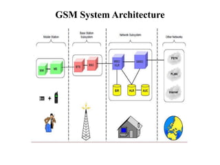
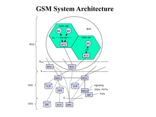
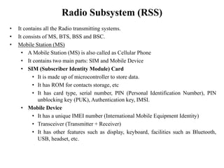
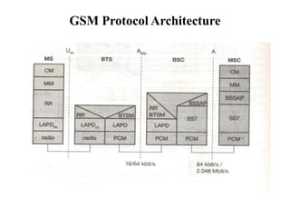
IT8602 Mobile Communication
Unit II - Mobile Telecommunication System
Kaviya.P
Kamaraj College of Engineering & Technology
Unit II – Mobile Telecommunication System
GSM – Architecture – Protocols – Connection
Establishment – Frequency Allocation – Routing –
Mobility Management – Security –GPRS- UMTS-
Architecture
Global System for Mobile Communications (GSM)
• It provides data services in addition to voice services. (2G Technology)
• GSM networks radio operate in four different frequencies.
• Most GSM networks operate either in the 900MHz or in the 1800MHz frequency
bands.
• Some countries in the American continent (especially USA and Canada) use the
850MHz and 1900MHz.
• The relatively rarely used 400MHz and 450MHz frequency bands are assigned in
some countries, notably Scandinavia.
• In the 900MHz band, the uplink frequency band is 890-915MHz, and the downlink
frequency band is 935-960MHz.
GSM Services
• GSM provides three main categories of services. These are:
– Bearer services
– Teleservices
– Supplementary services
GSM Services - Bearer services
• Subscribers can send and receive data to/from remote computers or mobile phones
at 300 - 9600bps.
• These services also enable the transparent transmission of data between GSM and
other networks like PSTN, ISDN, etc.
• They are implemented on lower-three layers of OSI reference model.
• It provides email, voice mailbox, internet access.
• It is also called as GSM data services.
• It permits either transparent (or) non-transparent, synchronous (or) asynchronous
data transmission.
GSM Services - Bearer services
• Transparent bearer services
• Uses functions of physical layer.
• Constant delay and throughput if no transmission errors occur.
• FEC (Forward Error Correction) is used to increase the quality of data
transmission.
• Non-transparent bearer services
• Uses protocols from layer II and III to implement Error correction and Flow
control
• Radio Link Protocol (RLP) is used to provide high level data link control.
GSM Services - Teleservices
• Telephony
– High quality digital voice transmission of bandwidth 3.1 kHz.
– Special codecs are also used for voice transmission.
• Emergency number
– Even when out of coverage area, subscriber can call some emergency
numbers.
– The same number is used throughout an area..
– This service is free of cost and mandatorily provided by all service
providers.
– This connection will automatically be set up with the closest emergency
centre.
• Short Messaging Service
– Using signaling channels, full duplex SMS can be sent and received of size
160 characters.
• Fax
– Analogue fax data can be converted to digital data using MODEM and
transmitted over analog telephone network.
GSM Services - Supplementary services
• User identification, call redirect, call forward, etc.
• Standard ISDN features such as „close user group‟ and „multiparty‟
communication are available. (conference calls)
GSM System Architecture
• A GSM system consists of three main subsystems:
– Radio Subsystem (RSS)
– Networking and Switching Subsystem (NSS)
– Operation Subsystem (OSS)
GSM System Architecture
Radio Subsystem (RSS)
• It contains all the Radio transmitting systems.
• It consists of MS, BTS, BSS and BSC.
• Mobile Station (MS)
• A Mobile Station (MS) is also called as Cellular Phone
• It contains two main parts: SIM and Mobile Device
• SIM (Subscriber Identity Module) Card
• It is made up of microcontroller to store data.
• It has ROM for contacts storage, etc
• It has card type, serial number, PIN (Personal Identification Number), PIN
unblocking key (PUK), Authentication key, IMSI.
• Mobile Device
• It has a unique IMEI number (International Mobile Equipment Identity)
• Transceiver (Transmitter + Receiver)
• It has other features such as display, keyboard, facilities such as Bluetooth,
USB, headset, etc.
Radio Subsystem (RSS)
• Base Station Subsystem (BSS)
• A GSM network has many BSS.
• Each BSS consists of one BSC and many BTS.
• BSS is responsible for maintaining all radio connections to an MS,
coding/decoding of voice.
• Base Transmitter Station (BTS)
• BTS consists of all radio equipment such as antenna, signal processors and
amplifiers for radio transmission.
• It encodes the received signal, modulates it on a carrier wave, and gives RF
signals to the antenna.
• It communicates with both MS and BSC.
• Base Station Controller (BSC)
• BSC assigns frequency and timeslots for all MS in its area.
• It manages handoff from one BTS to another within BSS.
• It performs multiplexing of radio signals onto fixed network connection to
the MSC.
Network and Switching Subsystem (NSS)
• It is the heart of GSM.
• It connects wireless networks to standard public networks.
• It performs amount charging for usage, accounting, roaming.
• It consists of MSC, GMSC, HLR and VLR.
• Mobile Switching Centre (MSC)
• It is the heart of the GSM network.
• It sets up connection to other MSC, and other Public Data Networks (PDN).
• It is responsible for connection setup, connection release, and call handoff to other
MSCs.
• Gateway Mobile Switching Centre (GMSC)
• It performs gateway functions when customers roam to other networks.
• It also provides supplementary services such as call forwarding, conference calls, etc.
Network and Switching Subsystem (NSS)
• Home Location register (HLR)
• It is a database to store important information of each subscriber.
• It contains prepaid (or) postpaid number.
• It contains static information like Mobile Subscriber ISDN Number
(MSISDN), IMSI, Current Location Area (LA) of the MS, Mobile
Subscriber Roaming Number (MSRN).
• Visitor Location Register (VLR)
• It is a temporary database to store information about a new MS when it
enters the coverage area (roaming).
• It gets information about MS from HLR.
• It reduces the number of queries to HLR and make the user feel as if he
were in his home network.
Operation Subsystem (OSS)
• It is needed for all network operations and maintenance.
• It contains OMC, AuC and EIR.
• Operation and Maintenance Center (OMC)
– It checks all other network entities
– It checks traffic, subscribers, security management, customer care,
accounting and billing.
• Authentication Centre (AuC)
– It protects the network against intruders and attackers.
– It has information about user authentication and encryption.
– It is related to HLR
• Equipment Identity Register (EIR)
– It is a database to track handsets using IMEI number.
– It helps to block calls from stolen, unauthorized, or defective mobiles.
GSM Protocol Architecture
Layer 1 - Physical Layer
• Handles all radio-specific functions
• This includes the creation of bursts according to the five different formats:
– Multiplexing of bursts into a TDMA frame
– Synchronization with the BTS
– Detection of idle channels
– Measurement of the channel quality on the downlink
• At Um uses GMSK for digital modulation
• Encryption / decryption not end to end (between BTS / MS)
• To maintain synchronization, always different RTT between MS and BTS
• Channel encoding and Error Detection/Correction - Employs Forward Error
Correction scheme (FEC)
• Voice Activity Detection (VAD): Transmits voice data only when there is a
voice signal. If there silence transmits some comfort noise signal is generated.
GSM Protocol Architecture
Layer 2 - LAPDm
• Signaling between entities in a GSM network requires higher layers.
• Link Access Procedure for the D-channel (LAPD) in ISDN systems, which is a
version of HDLC.
• LAPDm is a lightweight LAPD because it does not need synchronization
flags or checksumming for error detection.
• LAPDm offers reliable data transfer over connections, re-sequencing of data
frames, and flow control.
• Services provided by LAPDm include segmentation and reassembly of data
and acknowledged/unacknowledged data transfer.
GSM Protocol Architecture
Layer 3 - comprises several sublayers.
• Radio Resource Management (RR):
– Main tasks of RR are setup, maintenance, and release of radio channels.
– The functions of RR‟ are supported by the BSC via the BTS management
(BTSM).
• Mobility Management (MM):
– Contains functions for registration, authentication, identification, location
updating, and the provision to replace International Mobile Subscriber
Identity (IMSI) by Temporary Mobile Subscriber Identity (TMSI).
GSM Protocol Architecture
Layer 3 - comprises several sublayers.
• Call Management (CM):
– Contains three entities: call control (CC), short message service (SMS),
and supplementary service (SS).
– Provides a point-to-point connection between two terminals
– Used by higher layers for call establishment, call clearing and change of
call parameters.
– Provides functions to send in-band tones, called dual tone multiple
frequency (DTMF), over the GSM network.
GSM Protocol Architecture
• Pulse Code Modulation (PCM):
– Used for Data transmission at the physical layer.
– While PCM systems offer transparent 64 kbit/s channels, GSM also allows
for the submultiplexing of four 16 kbit/s channels into a single 64 kbit/s
channel.
• LAPD is used for layer two at Abis, BTSM for BTS management.
• Signaling system No. 7 (SS7):
– Used for signaling between an MSC and a BSC.
– Transfers all management information between MSCs, HLR, VLRs, AuC,
EIR, and OMC.
– A MSC can also control a BSS via a BSS application part (BSSAP).
GSM Localization and Calling
• GSM knows where a user currently is, and the same phone number is valid
worldwide.
• To provide this service, GSM performs periodic location updates even if a user
does not use the mobile station.
• The HLR always contains information about the current location (only the
location area, not the precise geographical location).
• The VLR currently responsible for the MS informs the HLR about location
changes.
• As soon as an MS moves into the range of a new VLR (a new location area), the
HLR sends all user data needed to the new VLR.
• Roaming: Changing VLRs with uninterrupted availability of all services.
GSM Localization and Calling
• To locate a MS and to address the MS, several numbers are needed:
– Mobile Station International ISDN Number (MSISDN)
– International Mobile Subscriber Identity (IMSI)
– Temporary Mobile Subscriber Identity (TMSI)
– Mobile Station Roaming Number (MSRN)
GSM Localization and Calling
• There are many systems operating in the background for connecting a call,
maintenance and conclusion of calls.
• Two types of calls TO and FROM the mobile phone.
• The call to a mobile unit from another mobile unit (or) a fixed landline is called
as MTC.
• Call initiated by a Mobile Station to another mobile station or a fixed landline is
called as MOC.
MTC - Mobile Terminated Call - Series of events
GSM Localization and Calling
1. User dials GSM number
2. PSTN identifies that number and forwards the call to GMSC
3. GMSC identifies HLR of the caller and makes call setup
4. HLR checks if the number exist or not, and requests MSRN from current VLR
5. VLR sends MSRN to HLR
6. HLR finds the suitable MSC for completing the call and forwards the information to
GMSC
7. GMSC forwards the call setup request to MSC
8. MSC asks VLR about current status of MS
9. VLR replies MSC about current status of MS
10. If MS is available, MSC initiates paging in all cells
11. BTS broadcasts paging information to all BSS
12. MS answers for paging information to BSS
13. BSS forwards paging information to MSC
MTC - Mobile Terminated Call - Series of events
GSM Localization and Calling
14. MSC forwards paging information to VLR for security check
15. VLR tells MSC to complete the call connection to MS
16. MSC tells BSS to complete the call connection to MS
17. BSS connects call to MS
• Mobile user does not know all these 17 events happening.
• Now the call is cleared for setup.
• Channel access is done through Random Access Channel
• Now the connection is changed to encrypted mode
• User is alerted by Ring tone.
• If user accepts the call, connection is continued.
• After call is disconnected, channel and the connection is released.
MTC - Mobile Terminated Call - Series of events
GSM Localization and Calling
MOC - Mobile Originated Call - Series of Events
GSM Localization and Calling
1. MS sends request to BSS for a new call connection
2. BSS forwards request to MSC
3. MSC asks VLR about callee status
4. VLR replies the status
5. GMSC asks PSTN for availability of callee.
6. Verification is done at PSTN
7. PSTN replies the verification information to GMSC
8. GMSC tells MSC that callee is available
9. MSC sets a connection with BSS
10. BSS sets a connection with MS.
MOC - Mobile Originated Call - Series of Events
GSM Localization and Calling
• Mobile user does not know all these 10 events happening.
• Now the call is cleared for setup.
• Channel access is done through Random Access Channel
• Now the connection is changed to encrypted mode
• User is alerted by Ring tone.
• If user accepts the call, connection is continued.
• Paging is not needed in MOC
• After call is disconnected, channel and the connection is released.
MOC - Mobile Originated Call - Series of Events
GSM Localization and Calling
Message Flow for MTC & MOC
GSM - Localization and Calling
GSM Localization and Calling
• Paging is only necessary for an MTC, then similar message exchanges follow.
• The first step in this context is the channel access via the random access channel
(RACH) with consecutive channel assignment.
• The channel assigned could be a traffic channel (TCH) or a slower signaling
channel SDCCH.
• The next steps, which are needed for communication security, comprise the
authentication of the MS and the switching to encrypted communication.
• The system now assigns TCH and SDCCH for the initial connection setup.
GSM Localization and Calling
• The following steps depend on the use of MTC or MOC.
• If someone is calling the MS, it answers now with ‘alerting’ that the MS is ringing
and with ‘connect’ that the user has pressed the connect button.
• The same actions happen the other way round if the MS has initiated the call. After
connection acknowledgement, both parties can exchange data.
• Closing the connection comprises a user-initiated disconnect message (both sides
can do this), followed by releasing the connection and the radio channel.
• Um Interface:
– Interface between MS and BTS.
– It uses SDMA in combination with TDMA,FDMA, FDD.
GSM Frequency Allocation
• Each of the channel is separated in time using a GSM TDMA frame.
• Duration of each frame – 4.615ms.
• Frame is divided into 8 slots - 577μs.
• Data is transmitted in portions called bursts.
• Guard Space - Prevent overlapping of data.
• Tail = 0 - Enhance receiver Performance.
• S → Flag - User data / Network control data.
• Training - Select strongest signal in Multipath Control.
• Burst - 546.5μs remaining 30.5μs are used as guard space.
GSM Frequency Allocation
• Burst
– Normal Burst - Tail normal user data.
– Frequency Correction Burst – Correct local oscillator to avoid
interference.
– Synchronization Burst - BTS and MS remain synchronization in turns of
link.
– Access Burst - Initial connection setup information between BTS and MS.
– Dummy Burst - No data to transmit.
GSM Frequency Allocation
• Logical Channels: Channel for data transmission
– Traffic Channels (TCH)
• Half rate TCH (11.2 kbps)
• Full rate TCH (22.4 kbps)
– Control Channels (CCH)
• Broadcast CCH (BCCH) - Unidirectional
• Common CCH (CCCH) - Unidirectional
– Paging CH (PCH)
– Random Access Channel (RACH)
– Dedicated CCH (DCCH) - Bidirectional
GSM Frequency Allocation
• BCCH: Uses frequency correction CCH (FCCH) and Synchronization CH (SCH)
sends data common to all MS. (Information & Synchronization Information)
• CCH: For connection setup - Initial connection setup network MS and BTS. PCH
for paging appropriate MS by BTS. RACH - If a MS wants to set up a call & to
send data to BTS.
• DCCH: As long as MS has not established a TCH with the BTS, → If we want to
send signaling information between BTS and MS → Stand alone CCH (SDCCH)
registration, authentication etc.
• If more signaling information need to be transmitted and TCH is already exists,
GSM uses Fast Associated DCCH (FACCH).
• SACCH: Slow associated DCCH used for sending system information like
channel quality and signal power level.
GSM Frequency Allocation
• Frame Hierarchy
GSM Frequency Allocation
GSM Mobility Management
• The mobile (MS) moves out of one cell to another it must be possible to retain
the connection. The process by which this occurs is known as handover or
handoff.
• Handover should not cause a cut-off, also called call drop. GSM aims at
maximum handover duration of 60 ms.
Reasons for a handover
• When MS moves away from BTS, signal strength decrease, increase in error
rate and quality of radio cell diminishes.
• Load balancing - Traffic in one cell is too high and shift some MS to other cells
with a lower load.
Types of Handoff
• Hard handoff: When mobile station is moving, the handoff is made, but call is
disconnected in-between or disturbed.
• Soft handoff: Handoff is made without any disturbance.
GSM Mobility Management
Types of Handover
• Intra cell handover: Changes the carrier frequency since the
narrowband interference makes transmission impossible at certain
range.
• Inter cell, Intra BSC Handover: Moves between cell but stays within
the same BSC.
• Inter BSC, Intra MSC: Moves from one BSC to another but stays
within the same MSC.
• Inter MSC Handover: Moves from one MSC to another.
GSM Mobility Management
Handover Decision
• The BSC collects all values (bit error rate and signal levels from uplink and
downlink) from BTS and MS and calculates average values.
• These values are then compared to thresholds, i.e., the handover margin
(HO_MARGIN), which includes some hysteresis to avoid a ping-pong effect.
• The ping-pong effect may occur in GSM – a value which is too high could
cause a cut-off, and a value which is too low could cause too many
handovers.
GSM Mobility Management
Handover Decision
GSM Mobility Management
Handover Procedure
GSM Mobility Management
Handover Procedure
• The MS sends its periodic measurements reports, the BTSold forwards these
reports to the BSCold together with its own measurements.
• Based on these values, the BSCold may decide to perform a handover and sends
the message HO_required to the MSC.
• The task of the MSC then comprises the request of the resources needed for the
handover from the new BSC, BSCnew.
• This BSC checks if enough resources are available and activates a physical
channel at the BTSnew to prepare for the arrival of the MS.
• The BTSnew acknowledges the successful channel activation, BSCnew
acknowledges the handover request.
GSM Mobility Management
Handover Procedure
• The MSC then issues a handover command that is forwarded to the MS.
• The MS now breaks its old radio link and accesses the new BTS.
• The next steps include the establishment of the link (this includes layer two link
establishment and handover complete messages from the MS).
• Basically, the MS has then finished the handover, but it is important to release
the resources at the old BSC and BTS and to signal the successful handover
using the handover and clear complete messages.
GSM Security
• Access control & Authentication: Setting password (Secret PIN). Challenge -
response scheme.
• Confidentiality: Data passed between BTS & MS are encrypted - no end to end
encryption.
• Anonymity: All user identification are never transmitted through air interface
because IMSI is replaced by TMSI.
• Algorithms
– A3 - Authentication
– A5 - Encryption
– A8 - Cipher key generation
GSM Security
Authentication
GSM Security
Authentication
• Before a subscriber can use any service from the GSM network, he or she must
be authenticated.
• Authentication is based on the SIM, which stores the individual authentication
key Ki, the user identification IMSI, and the algorithm used for authentication
A3.
• Authentication uses a challenge-response method: The access control AC
generates a random number RAND as challenge, and the SIM within the MS
answers with SRES (signed response) as response.
GSM Security
Authentication
• The AuC performs the basic generation of random values RAND, signed
responses SRES, and cipher keys Kc for each IMSI, and then forwards this
information to the HLR.
• The current VLR requests the appropriate values for RAND, SRES, and Kc
form the HLR.
• For authentication, the VLR sends the random value RAND to the SIM.
• Both sides, network and subscriber module, perform the same operation with
RAND and the key Ki, called A3.
• The MS sends back the SRES generated by the SIM; the VLR can now compare
both values. If they are the same, the VLR accepts the subscriber, otherwise the
subscriber is rejected.
GSM Security
Encryption
GSM Security
Encryption
• To ensure privacy, all messages containing user related information are
encrypted is GSM over the air interface.
• After authentication, MS and BSS can start using encryption by applying the
cipher key Kc.
• Kc is generated using the individual key Ki and a random value by applying the
algorithm A8.
• The SIM in the MS and the network both calculate the same Kc based on the
random value RAND.
• The key Kc itself is not transmitted over the air interface.
General Packet Radio Service (GPRS)
• It is combined with GSM for improving internet access.
• Transfers data packets from GSM mobiles to packet data networks (PDN).
• Packets can be directly routed from GPRS mobiles to packet-switched
networks, therefore easy to connect to internet.
• In GSM, it is charged for duration of connection, but in GPRS, it is charged for
amount of data packets transmitted.
• GSM is for voice communication (2G). But then, there was a need for data
communication.
• 9.6 kbps speed of GSM was not sufficient for data communication. Therefore
GPRS has evolved.
• File upload and download, web browsing and email exchanging are some of the
features of GPRS.
GPRS Services
GPRS offers end-to-end packet-switched data transfer services which can be
categorized into the following types:
• Point-to-Point (PTP) service
– The PTP service is between two users and can either be connectionless or
connection-oriented.
• Point-to-Multipoint (PTM) service
– The PTM is a data service from one user to multiple users.
– There are two types of PTM services.
– Multicast PTM - The data packets are broadcast in a certain area.
– Group call PTM - The data packets are addressed to a group of users.
GPRS Architecture
• It is the extension of GSM architecture.
• In GPRS, data is transmitted in packets.
• It is flexible and more powerful.
• It works on packet switching, not circuit switching.
• It gives better QoS (Quality of Service).
• It allows broadband broadcast, multicast and unicast.
• Additional hardware and software is required.
• Data transfer rate up to 150 kbps.
GPRS Architecture
GPRS Architecture
GPRS Architecture
• SGSN and GGSN are the newly introduced elements.
– SGSN – Servicing GRPS Support Node
– GGSN – Gateway GPRS Support Node
• SGSN acts like a router. All SGSN are connected to a standard GSM architecture
• GGSN is the internetworking unit between the GPRS network and PDN.
• GGSN contains routing information for GPRS users, performs address connection and
securely tunnels data to a user through encapsulation.
• GGSN is connected to an external network and it transfers packets to SGSN through IP-
based GPRS backbone network.
• SGSN helps support MS. It is connected to BSC through frame relay. It is at the same
hierarchy level as the MSC.
• The GPRS Register (GR) is a part of HLR which stores all relevant GPRS data.
• Data packets are transmitted to the BSS and finally to MS through GGSN and SGSN.
GPRS Advantages and Limitations
• Advantages
– Machine-to-machine data communication.
– Lower service charges.
– Compatible with E-mail, broadcast services, and web browsing.
– Web-based services, e-Commerce, and advertising is also supported (High
speed packet-switched communication supported by GPRS).
• Limitations
– Reduced cell capacity.
– Transmission delay.
– No storage mechanism.
GPRS Protocol Architecture
apps.
IP/X.25
LLC
GTP
MAC
radio
MAC
radio
FR
RLC BSSGP
IP/X.25
FR
Um Gb Gn
L1/L2 L1/L2
MS BSS SGSN GGSN
UDP/TCP
Gi
SNDCP
RLC BSSGP IP IP
LLC UDP/TCP
SNDCP GTP
GPRS Protocol Architecture
• GPRS Tunneling Protocol (GTP): All the data within GPRS backbone transferred
using GTP.
• GTP can use two different protocols (TCP-reliable / UDP-unreliable).
• Subnetwork Dependent Convergence Protocol (SNDCP): To adapt to the different
characteristics of the underlying networks. Used between an SGSN and the MS.
• Base Station Subsystem GPRS Protocol (BSSGP): Conveys routing information &
QoS related information between BSS and SGSN.
• Frame Relay (FR): Performs error correction.
• Logical Link Protocol (LLC): To achieve a high reliability of packet transfer
between SGSN and MS. Uses ARQ and FEC mechanisms for PTP & PTM services.
• Radio Link Protocol (RLC): Provides reliable link.
• Medium Access Control (MAC): Controls access with signaling procedure.
Universal Mobile Telecommunication
System (UMTS)
• CDMA2000 & UMTS are the 3G standards approved by ITU.
• In these networks, coverage is provided by a combination of various cell sizes,
ranging from “in building” pico cells to global cells provided by satellites, giving
service to the remote regions of the world.
• Advantage: It gives significantly enhanced capacities to operators.
• UMTS systems are compatible with GSM networks. UMTS networks can easily
work with any existing GSM/GPRS network.
• Minimum data rate of 144kbps - rural outdoor access at a speed of 500kmph.
• Minimum data rate of 384kbps - suburban outdoor access at a speed of 120 kmph.
• Maximum data rate of 2Mbps - urban indoor use at a speed of 10kmph.
UMTS Services
• Higher Speech Quality: In addition to speech traffic, it supports advanced data and
information service - true multimedia network.
• Higher Data rate: The UMTS supports 2 Mbps data rate much higher than 2G.
• Virtual Home Environment (VHE): A user roaming from his network to other
UMTS network will not feel any discontinuity or service difference - giving the
feeling of being in the home network. In 2G a user registered to a visitor location and
is also charged a roaming overheads.
UMTS Architecture
• UTRA Network (UTRAN)
– Handles cell level mobility.
– Comprises several radio network subsystems (RNS).
– Radio channel ciphering and deciphering.
– Handover control.
– Radio resource management.
• The UTRAN is connected to the User Equipment (UE) via the radio interface Uu
(which is comparable to the Um interface in GSM).
• UTRAN communicates with the Core Network (CN) via the Iu interface (which is
similar to the A interface in GSM).
UMTS Architecture
• The CN contains functions for
– Inter-system handover
– Gateways to other networks (fixed or wireless)
– Performs location management if there is no dedicated connection between UE
and UTRAN.
• UMTS further subdivides the above simplified architecture into so-called domains.
UMTS Architecture
• User Equipment Domain
– Assigned to a single user in order to access UMTS services.
– Universal Subscriber Identity Module (USIM)
• Contains the SIM for UMTS.
• Performs functions for encryption and authentication of users.
• Stores all the necessary user-related data for UMTS.
– Mobile Equipment Domain
• End Device.
• Performs radio transmission.
• User interface for establishing & maintaining end-to-end connections.
UMTS Architecture
• Infrastructure Domain
– Shared among all users.
– Offers UMTS services to all accepted users.
– Access Network Domain: Contains the radio access networks (RAN).
– Core Network Domain: Contains access network independent functions.
• Serving Network Domain: Comprises all functions currently used by the
user for accessing UMTS services.
• Home Network Domain: All functions related to the home network of a
user. (Eg: User data looks-up)
• Transit Network Domain: May be necessary if, for example, the serving
network cannot directly contact the home network.

IT8602 Mobile Communication Unit II

  • 1.
    IT8602 Mobile Communication UnitII - Mobile Telecommunication System Kaviya.P Kamaraj College of Engineering & Technology
  • 2.
    Unit II –Mobile Telecommunication System GSM – Architecture – Protocols – Connection Establishment – Frequency Allocation – Routing – Mobility Management – Security –GPRS- UMTS- Architecture
  • 3.
    Global System forMobile Communications (GSM) • It provides data services in addition to voice services. (2G Technology) • GSM networks radio operate in four different frequencies. • Most GSM networks operate either in the 900MHz or in the 1800MHz frequency bands. • Some countries in the American continent (especially USA and Canada) use the 850MHz and 1900MHz. • The relatively rarely used 400MHz and 450MHz frequency bands are assigned in some countries, notably Scandinavia. • In the 900MHz band, the uplink frequency band is 890-915MHz, and the downlink frequency band is 935-960MHz.
  • 4.
    GSM Services • GSMprovides three main categories of services. These are: – Bearer services – Teleservices – Supplementary services
  • 5.
    GSM Services -Bearer services • Subscribers can send and receive data to/from remote computers or mobile phones at 300 - 9600bps. • These services also enable the transparent transmission of data between GSM and other networks like PSTN, ISDN, etc. • They are implemented on lower-three layers of OSI reference model. • It provides email, voice mailbox, internet access. • It is also called as GSM data services. • It permits either transparent (or) non-transparent, synchronous (or) asynchronous data transmission.
  • 6.
    GSM Services -Bearer services • Transparent bearer services • Uses functions of physical layer. • Constant delay and throughput if no transmission errors occur. • FEC (Forward Error Correction) is used to increase the quality of data transmission. • Non-transparent bearer services • Uses protocols from layer II and III to implement Error correction and Flow control • Radio Link Protocol (RLP) is used to provide high level data link control.
  • 7.
    GSM Services -Teleservices • Telephony – High quality digital voice transmission of bandwidth 3.1 kHz. – Special codecs are also used for voice transmission. • Emergency number – Even when out of coverage area, subscriber can call some emergency numbers. – The same number is used throughout an area.. – This service is free of cost and mandatorily provided by all service providers. – This connection will automatically be set up with the closest emergency centre. • Short Messaging Service – Using signaling channels, full duplex SMS can be sent and received of size 160 characters. • Fax – Analogue fax data can be converted to digital data using MODEM and transmitted over analog telephone network.
  • 8.
    GSM Services -Supplementary services • User identification, call redirect, call forward, etc. • Standard ISDN features such as „close user group‟ and „multiparty‟ communication are available. (conference calls)
  • 9.
    GSM System Architecture •A GSM system consists of three main subsystems: – Radio Subsystem (RSS) – Networking and Switching Subsystem (NSS) – Operation Subsystem (OSS)
  • 10.
  • 11.
  • 12.
    Radio Subsystem (RSS) •It contains all the Radio transmitting systems. • It consists of MS, BTS, BSS and BSC. • Mobile Station (MS) • A Mobile Station (MS) is also called as Cellular Phone • It contains two main parts: SIM and Mobile Device • SIM (Subscriber Identity Module) Card • It is made up of microcontroller to store data. • It has ROM for contacts storage, etc • It has card type, serial number, PIN (Personal Identification Number), PIN unblocking key (PUK), Authentication key, IMSI. • Mobile Device • It has a unique IMEI number (International Mobile Equipment Identity) • Transceiver (Transmitter + Receiver) • It has other features such as display, keyboard, facilities such as Bluetooth, USB, headset, etc.
  • 13.
    Radio Subsystem (RSS) •Base Station Subsystem (BSS) • A GSM network has many BSS. • Each BSS consists of one BSC and many BTS. • BSS is responsible for maintaining all radio connections to an MS, coding/decoding of voice. • Base Transmitter Station (BTS) • BTS consists of all radio equipment such as antenna, signal processors and amplifiers for radio transmission. • It encodes the received signal, modulates it on a carrier wave, and gives RF signals to the antenna. • It communicates with both MS and BSC. • Base Station Controller (BSC) • BSC assigns frequency and timeslots for all MS in its area. • It manages handoff from one BTS to another within BSS. • It performs multiplexing of radio signals onto fixed network connection to the MSC.
  • 14.
    Network and SwitchingSubsystem (NSS) • It is the heart of GSM. • It connects wireless networks to standard public networks. • It performs amount charging for usage, accounting, roaming. • It consists of MSC, GMSC, HLR and VLR. • Mobile Switching Centre (MSC) • It is the heart of the GSM network. • It sets up connection to other MSC, and other Public Data Networks (PDN). • It is responsible for connection setup, connection release, and call handoff to other MSCs. • Gateway Mobile Switching Centre (GMSC) • It performs gateway functions when customers roam to other networks. • It also provides supplementary services such as call forwarding, conference calls, etc.
  • 15.
    Network and SwitchingSubsystem (NSS) • Home Location register (HLR) • It is a database to store important information of each subscriber. • It contains prepaid (or) postpaid number. • It contains static information like Mobile Subscriber ISDN Number (MSISDN), IMSI, Current Location Area (LA) of the MS, Mobile Subscriber Roaming Number (MSRN). • Visitor Location Register (VLR) • It is a temporary database to store information about a new MS when it enters the coverage area (roaming). • It gets information about MS from HLR. • It reduces the number of queries to HLR and make the user feel as if he were in his home network.
  • 16.
    Operation Subsystem (OSS) •It is needed for all network operations and maintenance. • It contains OMC, AuC and EIR. • Operation and Maintenance Center (OMC) – It checks all other network entities – It checks traffic, subscribers, security management, customer care, accounting and billing. • Authentication Centre (AuC) – It protects the network against intruders and attackers. – It has information about user authentication and encryption. – It is related to HLR • Equipment Identity Register (EIR) – It is a database to track handsets using IMEI number. – It helps to block calls from stolen, unauthorized, or defective mobiles.
  • 17.
  • 18.
    GSM Protocol Architecture Layer1 - Physical Layer • Handles all radio-specific functions • This includes the creation of bursts according to the five different formats: – Multiplexing of bursts into a TDMA frame – Synchronization with the BTS – Detection of idle channels – Measurement of the channel quality on the downlink • At Um uses GMSK for digital modulation • Encryption / decryption not end to end (between BTS / MS) • To maintain synchronization, always different RTT between MS and BTS • Channel encoding and Error Detection/Correction - Employs Forward Error Correction scheme (FEC) • Voice Activity Detection (VAD): Transmits voice data only when there is a voice signal. If there silence transmits some comfort noise signal is generated.
  • 19.
    GSM Protocol Architecture Layer2 - LAPDm • Signaling between entities in a GSM network requires higher layers. • Link Access Procedure for the D-channel (LAPD) in ISDN systems, which is a version of HDLC. • LAPDm is a lightweight LAPD because it does not need synchronization flags or checksumming for error detection. • LAPDm offers reliable data transfer over connections, re-sequencing of data frames, and flow control. • Services provided by LAPDm include segmentation and reassembly of data and acknowledged/unacknowledged data transfer.
  • 20.
    GSM Protocol Architecture Layer3 - comprises several sublayers. • Radio Resource Management (RR): – Main tasks of RR are setup, maintenance, and release of radio channels. – The functions of RR‟ are supported by the BSC via the BTS management (BTSM). • Mobility Management (MM): – Contains functions for registration, authentication, identification, location updating, and the provision to replace International Mobile Subscriber Identity (IMSI) by Temporary Mobile Subscriber Identity (TMSI).
  • 21.
    GSM Protocol Architecture Layer3 - comprises several sublayers. • Call Management (CM): – Contains three entities: call control (CC), short message service (SMS), and supplementary service (SS). – Provides a point-to-point connection between two terminals – Used by higher layers for call establishment, call clearing and change of call parameters. – Provides functions to send in-band tones, called dual tone multiple frequency (DTMF), over the GSM network.
  • 22.
    GSM Protocol Architecture •Pulse Code Modulation (PCM): – Used for Data transmission at the physical layer. – While PCM systems offer transparent 64 kbit/s channels, GSM also allows for the submultiplexing of four 16 kbit/s channels into a single 64 kbit/s channel. • LAPD is used for layer two at Abis, BTSM for BTS management. • Signaling system No. 7 (SS7): – Used for signaling between an MSC and a BSC. – Transfers all management information between MSCs, HLR, VLRs, AuC, EIR, and OMC. – A MSC can also control a BSS via a BSS application part (BSSAP).
  • 23.
    GSM Localization andCalling • GSM knows where a user currently is, and the same phone number is valid worldwide. • To provide this service, GSM performs periodic location updates even if a user does not use the mobile station. • The HLR always contains information about the current location (only the location area, not the precise geographical location). • The VLR currently responsible for the MS informs the HLR about location changes. • As soon as an MS moves into the range of a new VLR (a new location area), the HLR sends all user data needed to the new VLR. • Roaming: Changing VLRs with uninterrupted availability of all services.
  • 24.
    GSM Localization andCalling • To locate a MS and to address the MS, several numbers are needed: – Mobile Station International ISDN Number (MSISDN) – International Mobile Subscriber Identity (IMSI) – Temporary Mobile Subscriber Identity (TMSI) – Mobile Station Roaming Number (MSRN)
  • 25.
    GSM Localization andCalling • There are many systems operating in the background for connecting a call, maintenance and conclusion of calls. • Two types of calls TO and FROM the mobile phone. • The call to a mobile unit from another mobile unit (or) a fixed landline is called as MTC. • Call initiated by a Mobile Station to another mobile station or a fixed landline is called as MOC.
  • 26.
    MTC - MobileTerminated Call - Series of events GSM Localization and Calling
  • 27.
    1. User dialsGSM number 2. PSTN identifies that number and forwards the call to GMSC 3. GMSC identifies HLR of the caller and makes call setup 4. HLR checks if the number exist or not, and requests MSRN from current VLR 5. VLR sends MSRN to HLR 6. HLR finds the suitable MSC for completing the call and forwards the information to GMSC 7. GMSC forwards the call setup request to MSC 8. MSC asks VLR about current status of MS 9. VLR replies MSC about current status of MS 10. If MS is available, MSC initiates paging in all cells 11. BTS broadcasts paging information to all BSS 12. MS answers for paging information to BSS 13. BSS forwards paging information to MSC MTC - Mobile Terminated Call - Series of events GSM Localization and Calling
  • 28.
    14. MSC forwardspaging information to VLR for security check 15. VLR tells MSC to complete the call connection to MS 16. MSC tells BSS to complete the call connection to MS 17. BSS connects call to MS • Mobile user does not know all these 17 events happening. • Now the call is cleared for setup. • Channel access is done through Random Access Channel • Now the connection is changed to encrypted mode • User is alerted by Ring tone. • If user accepts the call, connection is continued. • After call is disconnected, channel and the connection is released. MTC - Mobile Terminated Call - Series of events GSM Localization and Calling
  • 29.
    MOC - MobileOriginated Call - Series of Events GSM Localization and Calling
  • 30.
    1. MS sendsrequest to BSS for a new call connection 2. BSS forwards request to MSC 3. MSC asks VLR about callee status 4. VLR replies the status 5. GMSC asks PSTN for availability of callee. 6. Verification is done at PSTN 7. PSTN replies the verification information to GMSC 8. GMSC tells MSC that callee is available 9. MSC sets a connection with BSS 10. BSS sets a connection with MS. MOC - Mobile Originated Call - Series of Events GSM Localization and Calling
  • 31.
    • Mobile userdoes not know all these 10 events happening. • Now the call is cleared for setup. • Channel access is done through Random Access Channel • Now the connection is changed to encrypted mode • User is alerted by Ring tone. • If user accepts the call, connection is continued. • Paging is not needed in MOC • After call is disconnected, channel and the connection is released. MOC - Mobile Originated Call - Series of Events GSM Localization and Calling
  • 32.
    Message Flow forMTC & MOC GSM - Localization and Calling
  • 33.
    GSM Localization andCalling • Paging is only necessary for an MTC, then similar message exchanges follow. • The first step in this context is the channel access via the random access channel (RACH) with consecutive channel assignment. • The channel assigned could be a traffic channel (TCH) or a slower signaling channel SDCCH. • The next steps, which are needed for communication security, comprise the authentication of the MS and the switching to encrypted communication. • The system now assigns TCH and SDCCH for the initial connection setup.
  • 34.
    GSM Localization andCalling • The following steps depend on the use of MTC or MOC. • If someone is calling the MS, it answers now with ‘alerting’ that the MS is ringing and with ‘connect’ that the user has pressed the connect button. • The same actions happen the other way round if the MS has initiated the call. After connection acknowledgement, both parties can exchange data. • Closing the connection comprises a user-initiated disconnect message (both sides can do this), followed by releasing the connection and the radio channel.
  • 35.
    • Um Interface: –Interface between MS and BTS. – It uses SDMA in combination with TDMA,FDMA, FDD. GSM Frequency Allocation
  • 36.
    • Each ofthe channel is separated in time using a GSM TDMA frame. • Duration of each frame – 4.615ms. • Frame is divided into 8 slots - 577μs. • Data is transmitted in portions called bursts. • Guard Space - Prevent overlapping of data. • Tail = 0 - Enhance receiver Performance. • S → Flag - User data / Network control data. • Training - Select strongest signal in Multipath Control. • Burst - 546.5μs remaining 30.5μs are used as guard space. GSM Frequency Allocation
  • 37.
    • Burst – NormalBurst - Tail normal user data. – Frequency Correction Burst – Correct local oscillator to avoid interference. – Synchronization Burst - BTS and MS remain synchronization in turns of link. – Access Burst - Initial connection setup information between BTS and MS. – Dummy Burst - No data to transmit. GSM Frequency Allocation
  • 38.
    • Logical Channels:Channel for data transmission – Traffic Channels (TCH) • Half rate TCH (11.2 kbps) • Full rate TCH (22.4 kbps) – Control Channels (CCH) • Broadcast CCH (BCCH) - Unidirectional • Common CCH (CCCH) - Unidirectional – Paging CH (PCH) – Random Access Channel (RACH) – Dedicated CCH (DCCH) - Bidirectional GSM Frequency Allocation
  • 39.
    • BCCH: Usesfrequency correction CCH (FCCH) and Synchronization CH (SCH) sends data common to all MS. (Information & Synchronization Information) • CCH: For connection setup - Initial connection setup network MS and BTS. PCH for paging appropriate MS by BTS. RACH - If a MS wants to set up a call & to send data to BTS. • DCCH: As long as MS has not established a TCH with the BTS, → If we want to send signaling information between BTS and MS → Stand alone CCH (SDCCH) registration, authentication etc. • If more signaling information need to be transmitted and TCH is already exists, GSM uses Fast Associated DCCH (FACCH). • SACCH: Slow associated DCCH used for sending system information like channel quality and signal power level. GSM Frequency Allocation
  • 40.
    • Frame Hierarchy GSMFrequency Allocation
  • 41.
    GSM Mobility Management •The mobile (MS) moves out of one cell to another it must be possible to retain the connection. The process by which this occurs is known as handover or handoff. • Handover should not cause a cut-off, also called call drop. GSM aims at maximum handover duration of 60 ms. Reasons for a handover • When MS moves away from BTS, signal strength decrease, increase in error rate and quality of radio cell diminishes. • Load balancing - Traffic in one cell is too high and shift some MS to other cells with a lower load. Types of Handoff • Hard handoff: When mobile station is moving, the handoff is made, but call is disconnected in-between or disturbed. • Soft handoff: Handoff is made without any disturbance.
  • 42.
    GSM Mobility Management Typesof Handover • Intra cell handover: Changes the carrier frequency since the narrowband interference makes transmission impossible at certain range. • Inter cell, Intra BSC Handover: Moves between cell but stays within the same BSC. • Inter BSC, Intra MSC: Moves from one BSC to another but stays within the same MSC. • Inter MSC Handover: Moves from one MSC to another.
  • 43.
  • 44.
    GSM Mobility Management HandoverDecision • The BSC collects all values (bit error rate and signal levels from uplink and downlink) from BTS and MS and calculates average values. • These values are then compared to thresholds, i.e., the handover margin (HO_MARGIN), which includes some hysteresis to avoid a ping-pong effect. • The ping-pong effect may occur in GSM – a value which is too high could cause a cut-off, and a value which is too low could cause too many handovers.
  • 45.
  • 46.
  • 47.
    GSM Mobility Management HandoverProcedure • The MS sends its periodic measurements reports, the BTSold forwards these reports to the BSCold together with its own measurements. • Based on these values, the BSCold may decide to perform a handover and sends the message HO_required to the MSC. • The task of the MSC then comprises the request of the resources needed for the handover from the new BSC, BSCnew. • This BSC checks if enough resources are available and activates a physical channel at the BTSnew to prepare for the arrival of the MS. • The BTSnew acknowledges the successful channel activation, BSCnew acknowledges the handover request.
  • 48.
    GSM Mobility Management HandoverProcedure • The MSC then issues a handover command that is forwarded to the MS. • The MS now breaks its old radio link and accesses the new BTS. • The next steps include the establishment of the link (this includes layer two link establishment and handover complete messages from the MS). • Basically, the MS has then finished the handover, but it is important to release the resources at the old BSC and BTS and to signal the successful handover using the handover and clear complete messages.
  • 49.
    GSM Security • Accesscontrol & Authentication: Setting password (Secret PIN). Challenge - response scheme. • Confidentiality: Data passed between BTS & MS are encrypted - no end to end encryption. • Anonymity: All user identification are never transmitted through air interface because IMSI is replaced by TMSI. • Algorithms – A3 - Authentication – A5 - Encryption – A8 - Cipher key generation
  • 50.
  • 51.
    GSM Security Authentication • Beforea subscriber can use any service from the GSM network, he or she must be authenticated. • Authentication is based on the SIM, which stores the individual authentication key Ki, the user identification IMSI, and the algorithm used for authentication A3. • Authentication uses a challenge-response method: The access control AC generates a random number RAND as challenge, and the SIM within the MS answers with SRES (signed response) as response.
  • 52.
    GSM Security Authentication • TheAuC performs the basic generation of random values RAND, signed responses SRES, and cipher keys Kc for each IMSI, and then forwards this information to the HLR. • The current VLR requests the appropriate values for RAND, SRES, and Kc form the HLR. • For authentication, the VLR sends the random value RAND to the SIM. • Both sides, network and subscriber module, perform the same operation with RAND and the key Ki, called A3. • The MS sends back the SRES generated by the SIM; the VLR can now compare both values. If they are the same, the VLR accepts the subscriber, otherwise the subscriber is rejected.
  • 53.
  • 54.
    GSM Security Encryption • Toensure privacy, all messages containing user related information are encrypted is GSM over the air interface. • After authentication, MS and BSS can start using encryption by applying the cipher key Kc. • Kc is generated using the individual key Ki and a random value by applying the algorithm A8. • The SIM in the MS and the network both calculate the same Kc based on the random value RAND. • The key Kc itself is not transmitted over the air interface.
  • 55.
    General Packet RadioService (GPRS) • It is combined with GSM for improving internet access. • Transfers data packets from GSM mobiles to packet data networks (PDN). • Packets can be directly routed from GPRS mobiles to packet-switched networks, therefore easy to connect to internet. • In GSM, it is charged for duration of connection, but in GPRS, it is charged for amount of data packets transmitted. • GSM is for voice communication (2G). But then, there was a need for data communication. • 9.6 kbps speed of GSM was not sufficient for data communication. Therefore GPRS has evolved. • File upload and download, web browsing and email exchanging are some of the features of GPRS.
  • 56.
    GPRS Services GPRS offersend-to-end packet-switched data transfer services which can be categorized into the following types: • Point-to-Point (PTP) service – The PTP service is between two users and can either be connectionless or connection-oriented. • Point-to-Multipoint (PTM) service – The PTM is a data service from one user to multiple users. – There are two types of PTM services. – Multicast PTM - The data packets are broadcast in a certain area. – Group call PTM - The data packets are addressed to a group of users.
  • 57.
    GPRS Architecture • Itis the extension of GSM architecture. • In GPRS, data is transmitted in packets. • It is flexible and more powerful. • It works on packet switching, not circuit switching. • It gives better QoS (Quality of Service). • It allows broadband broadcast, multicast and unicast. • Additional hardware and software is required. • Data transfer rate up to 150 kbps.
  • 58.
  • 59.
  • 60.
    GPRS Architecture • SGSNand GGSN are the newly introduced elements. – SGSN – Servicing GRPS Support Node – GGSN – Gateway GPRS Support Node • SGSN acts like a router. All SGSN are connected to a standard GSM architecture • GGSN is the internetworking unit between the GPRS network and PDN. • GGSN contains routing information for GPRS users, performs address connection and securely tunnels data to a user through encapsulation. • GGSN is connected to an external network and it transfers packets to SGSN through IP- based GPRS backbone network. • SGSN helps support MS. It is connected to BSC through frame relay. It is at the same hierarchy level as the MSC. • The GPRS Register (GR) is a part of HLR which stores all relevant GPRS data. • Data packets are transmitted to the BSS and finally to MS through GGSN and SGSN.
  • 61.
    GPRS Advantages andLimitations • Advantages – Machine-to-machine data communication. – Lower service charges. – Compatible with E-mail, broadcast services, and web browsing. – Web-based services, e-Commerce, and advertising is also supported (High speed packet-switched communication supported by GPRS). • Limitations – Reduced cell capacity. – Transmission delay. – No storage mechanism.
  • 62.
    GPRS Protocol Architecture apps. IP/X.25 LLC GTP MAC radio MAC radio FR RLCBSSGP IP/X.25 FR Um Gb Gn L1/L2 L1/L2 MS BSS SGSN GGSN UDP/TCP Gi SNDCP RLC BSSGP IP IP LLC UDP/TCP SNDCP GTP
  • 63.
    GPRS Protocol Architecture •GPRS Tunneling Protocol (GTP): All the data within GPRS backbone transferred using GTP. • GTP can use two different protocols (TCP-reliable / UDP-unreliable). • Subnetwork Dependent Convergence Protocol (SNDCP): To adapt to the different characteristics of the underlying networks. Used between an SGSN and the MS. • Base Station Subsystem GPRS Protocol (BSSGP): Conveys routing information & QoS related information between BSS and SGSN. • Frame Relay (FR): Performs error correction. • Logical Link Protocol (LLC): To achieve a high reliability of packet transfer between SGSN and MS. Uses ARQ and FEC mechanisms for PTP & PTM services. • Radio Link Protocol (RLC): Provides reliable link. • Medium Access Control (MAC): Controls access with signaling procedure.
  • 64.
    Universal Mobile Telecommunication System(UMTS) • CDMA2000 & UMTS are the 3G standards approved by ITU. • In these networks, coverage is provided by a combination of various cell sizes, ranging from “in building” pico cells to global cells provided by satellites, giving service to the remote regions of the world. • Advantage: It gives significantly enhanced capacities to operators. • UMTS systems are compatible with GSM networks. UMTS networks can easily work with any existing GSM/GPRS network. • Minimum data rate of 144kbps - rural outdoor access at a speed of 500kmph. • Minimum data rate of 384kbps - suburban outdoor access at a speed of 120 kmph. • Maximum data rate of 2Mbps - urban indoor use at a speed of 10kmph.
  • 65.
    UMTS Services • HigherSpeech Quality: In addition to speech traffic, it supports advanced data and information service - true multimedia network. • Higher Data rate: The UMTS supports 2 Mbps data rate much higher than 2G. • Virtual Home Environment (VHE): A user roaming from his network to other UMTS network will not feel any discontinuity or service difference - giving the feeling of being in the home network. In 2G a user registered to a visitor location and is also charged a roaming overheads.
  • 66.
    UMTS Architecture • UTRANetwork (UTRAN) – Handles cell level mobility. – Comprises several radio network subsystems (RNS). – Radio channel ciphering and deciphering. – Handover control. – Radio resource management. • The UTRAN is connected to the User Equipment (UE) via the radio interface Uu (which is comparable to the Um interface in GSM). • UTRAN communicates with the Core Network (CN) via the Iu interface (which is similar to the A interface in GSM).
  • 67.
    UMTS Architecture • TheCN contains functions for – Inter-system handover – Gateways to other networks (fixed or wireless) – Performs location management if there is no dedicated connection between UE and UTRAN. • UMTS further subdivides the above simplified architecture into so-called domains.
  • 68.
    UMTS Architecture • UserEquipment Domain – Assigned to a single user in order to access UMTS services. – Universal Subscriber Identity Module (USIM) • Contains the SIM for UMTS. • Performs functions for encryption and authentication of users. • Stores all the necessary user-related data for UMTS. – Mobile Equipment Domain • End Device. • Performs radio transmission. • User interface for establishing & maintaining end-to-end connections.
  • 69.
    UMTS Architecture • InfrastructureDomain – Shared among all users. – Offers UMTS services to all accepted users. – Access Network Domain: Contains the radio access networks (RAN). – Core Network Domain: Contains access network independent functions. • Serving Network Domain: Comprises all functions currently used by the user for accessing UMTS services. • Home Network Domain: All functions related to the home network of a user. (Eg: User data looks-up) • Transit Network Domain: May be necessary if, for example, the serving network cannot directly contact the home network.