This document provides information on centrifugal pump classification, installation, maintenance, and troubleshooting. It includes classifications based on ANSI/API standards for overhung, between bearing, and vertically suspended pump designs. The document also details maintenance procedures and checklists for pump systems, mechanical components, electrical systems, diesel engines, and more. Common centrifugal pump problems like low flow are addressed along with potential causes such as air leaks, low speed, and high system head.


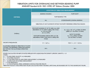


![S.G.= 0.8
Atm. Press
14m Total Line Losses = 5m
Vapor Press = 0.3 kg/cm2
NPSH (A) = [ Z (m) + Atm Press. ] – [Line Losses+ Vapor Press]
= [14 + ( 1.03 x 10/0.8 ) ] –
[ 5 + 0.3 x 10 / 0.8 ) ]
= ?????
NPSH ( A ) Calculation](https://image.slidesharecdn.com/centrifugalpumpstraining-230203132509-a1344987/85/CENTRIFUGAL-PUMPS-TRAINING-pdf-68-320.jpg)