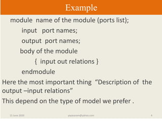
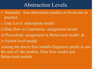
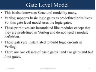
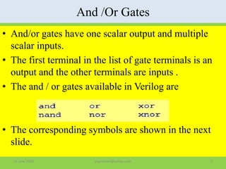
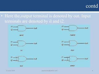
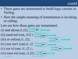
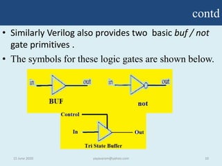
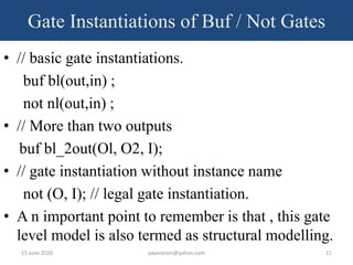
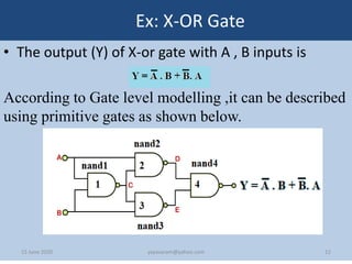
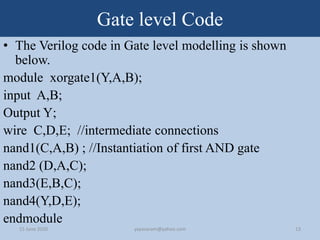
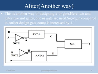
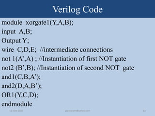
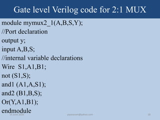
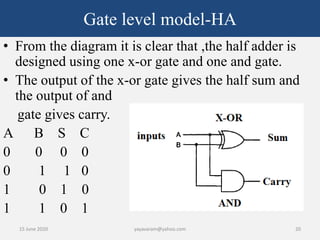
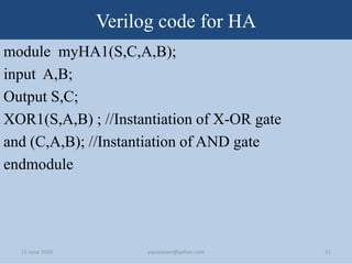
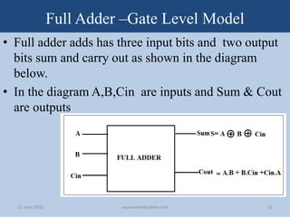
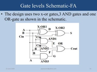
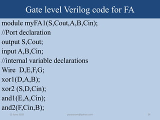
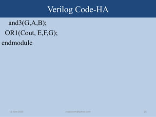
Digital Design Using Verilog -For Absolute Beginners
LECTURE3:GATE LEVEL MODELLING
EPILOGUE
• It’s a very well known fact that Verilog is a popular
HDL language used in the Design and Verification
of Digital Systems.
• HDL-Hardware description Language is a computer
based language that describes the hardware of a
digital system(Like logic gates, Multiplexers ,
Decoders, Adders , Flip-flops, Counters , Registers,
ALU, Memory etc.)
• This Verilog is very much similar to high level
software language ‘C’
15 June 2020 2yayavaram@yahoo.com
contd
• You have learnt in the first video of this series that,
the important part of the Verilog structure is the
Module.
• Every module has two parts . One is Declaration
part and the other is the body.
• The declaration part has the name of the module,
ports list and declaration of the ports.
• The body which is the main part , of the module
represents the input ,output relations.
15 June 2020 3yayavaram@yahoo.com
Example
module name of the module (ports list);
input port names;
output port names;
body of the module
{ input out relations }
endmodule
Here the most important thing “Description of the
output –input relations”
This depend on the type of model we prefer .
15 June 2020 4yayavaram@yahoo.com
Abstraction Levels.
• Normally, four abstraction models or levels are in
practice.
i. Gate Level description model
ii.Data flow or Continuous assignment model
iii.Procedural assignment or Behavioral model &
iv.Switch level model.
Among the above four models Engineers prefer to use
the mix of the models, Data flow model and
Behavioral models .
15 June 2020 5yayavaram@yahoo.com
Gate Level Model
• This is also known as Structural model by many.
• Verilog supports basic logic gates as predefined primitives.
So, this gate level model uses the logic gates.
• These primitives are instantiated like modules except that
they are predefined in Verilog and do not need a module
definition.
• These gates are instantiated to build logic circuits in
Verilog.
• There are two classes of basic gates : and / or gates and buf
/ not gates.
15 June 2020 6yayavaram@yahoo.com
And /Or Gates
• And/or gates have one scalar output and multiple
scalar inputs.
• The first terminal in the list of gate terminals is an
output and the other terminals are inputs .
• The and / or gates available in Verilog are
• The corresponding symbols are shown in the next
slide.
15 June 2020 7yayavaram@yahoo.com
contd
• Here the,output terminal is denoted by out. Input
terminals are denoted by il and i2.
15 June 2020 8yayavaram@yahoo.com
contd
• These gates are instantiated to build logic circuits in
Verilog.
• Here the simple meaning of instantiation is invoking
or calling.
Lets see how these gates are instantiated.
(i) and al(out,i1,i2);
(ii) nand nal (out, i1i2 ) ;
(iii) or orl(out,i1, i2);
(iv) nor nor1 (out,i1, i2 ) ;
(v) xor xl (out, i1, i2 ) ;
(vi) xnor nxl (out, i1,i2) ;
15 June 2020 9yayavaram@yahoo.com
contd
• Similarly Verilog also provides two basic buf / not
gate primitives .
• The symbols for these logic gates are shown below.
15 June 2020 10yayavaram@yahoo.com
Gate Instantiations of Buf / Not Gates
• // basic gate instantiations.
buf bl(out,in) ;
not nl(out,in) ;
• // More than two outputs
buf bl_2out(Ol, O2, I);
• // gate instantiation without instance name
not (O, I); // legal gate instantiation.
• A n important point to remember is that , this gate
level model is also termed as structural modelling.
15 June 2020 11yayavaram@yahoo.com
Ex: X-OR Gate
• The output (Y) of X-or gate with A , B inputs is
According to Gate level modelling ,it can be described
using primitive gates as shown below.
15 June 2020 12yayavaram@yahoo.com
Gate level Code
• The Verilog code in Gate level modelling is shown
below.
module xorgate1(Y,A,B);
input A,B;
Output Y;
wire C,D,E; //intermediate connections
nand1(C,A,B) ; //Instantiation of first AND gate
nand2 (D,A,C);
nand3(E,B,C);
nand4(Y,D,E);
endmodule
15 June 2020 13yayavaram@yahoo.com
Aliter(Another way)
• This is another way of designing x-or gate.Here two and
gates,two not gates, one or gate are used.So,wgen compared
to earlier design gate count is increased by 1.
15 June 2020 14yayavaram@yahoo.com
Verilog Code
module xorgate1(Y,A,B);
input A,B;
Output Y;
wire C,D,E; //intermediate connections
not 1(A’,A) ; //Instantiation of first NOT gate
not2 (B’,B); //Instantiation of second NOT gate
and1(C,B,A’);
and2(D,A,B’);
OR1(Y,C,D);
endmodule
15 June 2020 15yayavaram@yahoo.com
Gate Level Design of Multiplexor(MUX)
• Below diagram denotes a 2:1 Mux in terms of basic
logic gates like And, Or, Not etc.
• A &B are inputs and A1,B1 are intermediate inputs
to or gate. Hence they are declared as ‘wire’. The
out put is
Gate Level Design of Multiplexor(MUX)
• The block diagram of 2:1 Mux is shown below.
Gate level Verilog code for 2:1 MUX
module mymux2_1(A,B,S,Y);
//Port declaration
output y;
input A,B,S;
//internal variable declarations
Wire S1,A1,B1;
not (S1,S);
and1 (A1,A,S1);
and2 (B1,B,S);
Or(Y,A1,B1);
endmodule15 June 2020 18yayavaram@yahoo.com
Gate Level Half-adder
• A half adder adds two binary numbers and outputs
as sum & carry as shown below.
• Here a, b are inputs s and c are outputs.
• This Half adder can be designed at the Gate level
using one XOR gate , one AND gate as shown in
the diagram.15 June 2020 19yayavaram@yahoo.com
Gate level model-HA
15 June 2020 20yayavaram@yahoo.com
• From the diagram it is clear that ,the half adder is
designed using one x-or gate and one and gate.
• The output of the x-or gate gives the half sum and
the output of and
gate gives carry.
A B S C
0 0 0 0
0 1 1 0
1 0 1 0
1 1 0 1
Verilog code for HA
module myHA1(S,C,A,B);
input A,B;
Output S,C;
XOR1(S,A,B) ; //Instantiation of X-OR gate
and (C,A,B); //Instantiation of AND gate
endmodule
15 June 2020 21yayavaram@yahoo.com
Full Adder –Gate Level Model
• Full adder adds has three input bits and two output
bits sum and carry out as shown in the diagram
below.
• In the diagram A,B,Cin are inputs and Sum & Cout
are outputs
15 June 2020 22yayavaram@yahoo.com
Gate levels Schematic-FA
• The design uses two x-or gates,3 AND gates and one
OR-gate as shown in the schematic.
15 June 2020 23yayavaram@yahoo.com
Gate level Verilog code for FA
module myFA1(S,Cout,A,B,Cin);
//Port declaration
output S,Cout;
input A,B,Cin;
//internal variable declarations
Wire D,E,F,G;
xor1(D,A,B);
xor2 (S,D,Cin);
and1(E,A,Cin);
and2(F,Cin,B);
15 June 2020 24yayavaram@yahoo.com
Verilog Code-HA
and3(G,A,B);
OR1(Cout, E,F,G);
endmodule
15 June 2020 25yayavaram@yahoo.com

Gate level design -For beginners

  • 1.
    Digital Design UsingVerilog -For Absolute Beginners LECTURE3:GATE LEVEL MODELLING
  • 2.
    EPILOGUE • It’s avery well known fact that Verilog is a popular HDL language used in the Design and Verification of Digital Systems. • HDL-Hardware description Language is a computer based language that describes the hardware of a digital system(Like logic gates, Multiplexers , Decoders, Adders , Flip-flops, Counters , Registers, ALU, Memory etc.) • This Verilog is very much similar to high level software language ‘C’ 15 June 2020 2yayavaram@yahoo.com
  • 3.
    contd • You havelearnt in the first video of this series that, the important part of the Verilog structure is the Module. • Every module has two parts . One is Declaration part and the other is the body. • The declaration part has the name of the module, ports list and declaration of the ports. • The body which is the main part , of the module represents the input ,output relations. 15 June 2020 3yayavaram@yahoo.com
  • 4.
    Example module name ofthe module (ports list); input port names; output port names; body of the module { input out relations } endmodule Here the most important thing “Description of the output –input relations” This depend on the type of model we prefer . 15 June 2020 4yayavaram@yahoo.com
  • 5.
    Abstraction Levels. • Normally,four abstraction models or levels are in practice. i. Gate Level description model ii.Data flow or Continuous assignment model iii.Procedural assignment or Behavioral model & iv.Switch level model. Among the above four models Engineers prefer to use the mix of the models, Data flow model and Behavioral models . 15 June 2020 5yayavaram@yahoo.com
  • 6.
    Gate Level Model •This is also known as Structural model by many. • Verilog supports basic logic gates as predefined primitives. So, this gate level model uses the logic gates. • These primitives are instantiated like modules except that they are predefined in Verilog and do not need a module definition. • These gates are instantiated to build logic circuits in Verilog. • There are two classes of basic gates : and / or gates and buf / not gates. 15 June 2020 6yayavaram@yahoo.com
  • 7.
    And /Or Gates •And/or gates have one scalar output and multiple scalar inputs. • The first terminal in the list of gate terminals is an output and the other terminals are inputs . • The and / or gates available in Verilog are • The corresponding symbols are shown in the next slide. 15 June 2020 7yayavaram@yahoo.com
  • 8.
    contd • Here the,outputterminal is denoted by out. Input terminals are denoted by il and i2. 15 June 2020 8yayavaram@yahoo.com
  • 9.
    contd • These gatesare instantiated to build logic circuits in Verilog. • Here the simple meaning of instantiation is invoking or calling. Lets see how these gates are instantiated. (i) and al(out,i1,i2); (ii) nand nal (out, i1i2 ) ; (iii) or orl(out,i1, i2); (iv) nor nor1 (out,i1, i2 ) ; (v) xor xl (out, i1, i2 ) ; (vi) xnor nxl (out, i1,i2) ; 15 June 2020 9yayavaram@yahoo.com
  • 10.
    contd • Similarly Verilogalso provides two basic buf / not gate primitives . • The symbols for these logic gates are shown below. 15 June 2020 10yayavaram@yahoo.com
  • 11.
    Gate Instantiations ofBuf / Not Gates • // basic gate instantiations. buf bl(out,in) ; not nl(out,in) ; • // More than two outputs buf bl_2out(Ol, O2, I); • // gate instantiation without instance name not (O, I); // legal gate instantiation. • A n important point to remember is that , this gate level model is also termed as structural modelling. 15 June 2020 11yayavaram@yahoo.com
  • 12.
    Ex: X-OR Gate •The output (Y) of X-or gate with A , B inputs is According to Gate level modelling ,it can be described using primitive gates as shown below. 15 June 2020 12yayavaram@yahoo.com
  • 13.
    Gate level Code •The Verilog code in Gate level modelling is shown below. module xorgate1(Y,A,B); input A,B; Output Y; wire C,D,E; //intermediate connections nand1(C,A,B) ; //Instantiation of first AND gate nand2 (D,A,C); nand3(E,B,C); nand4(Y,D,E); endmodule 15 June 2020 13yayavaram@yahoo.com
  • 14.
    Aliter(Another way) • Thisis another way of designing x-or gate.Here two and gates,two not gates, one or gate are used.So,wgen compared to earlier design gate count is increased by 1. 15 June 2020 14yayavaram@yahoo.com
  • 15.
    Verilog Code module xorgate1(Y,A,B); inputA,B; Output Y; wire C,D,E; //intermediate connections not 1(A’,A) ; //Instantiation of first NOT gate not2 (B’,B); //Instantiation of second NOT gate and1(C,B,A’); and2(D,A,B’); OR1(Y,C,D); endmodule 15 June 2020 15yayavaram@yahoo.com
  • 16.
    Gate Level Designof Multiplexor(MUX) • Below diagram denotes a 2:1 Mux in terms of basic logic gates like And, Or, Not etc. • A &B are inputs and A1,B1 are intermediate inputs to or gate. Hence they are declared as ‘wire’. The out put is
  • 17.
    Gate Level Designof Multiplexor(MUX) • The block diagram of 2:1 Mux is shown below.
  • 18.
    Gate level Verilogcode for 2:1 MUX module mymux2_1(A,B,S,Y); //Port declaration output y; input A,B,S; //internal variable declarations Wire S1,A1,B1; not (S1,S); and1 (A1,A,S1); and2 (B1,B,S); Or(Y,A1,B1); endmodule15 June 2020 18yayavaram@yahoo.com
  • 19.
    Gate Level Half-adder •A half adder adds two binary numbers and outputs as sum & carry as shown below. • Here a, b are inputs s and c are outputs. • This Half adder can be designed at the Gate level using one XOR gate , one AND gate as shown in the diagram.15 June 2020 19yayavaram@yahoo.com
  • 20.
    Gate level model-HA 15June 2020 20yayavaram@yahoo.com • From the diagram it is clear that ,the half adder is designed using one x-or gate and one and gate. • The output of the x-or gate gives the half sum and the output of and gate gives carry. A B S C 0 0 0 0 0 1 1 0 1 0 1 0 1 1 0 1
  • 21.
    Verilog code forHA module myHA1(S,C,A,B); input A,B; Output S,C; XOR1(S,A,B) ; //Instantiation of X-OR gate and (C,A,B); //Instantiation of AND gate endmodule 15 June 2020 21yayavaram@yahoo.com
  • 22.
    Full Adder –GateLevel Model • Full adder adds has three input bits and two output bits sum and carry out as shown in the diagram below. • In the diagram A,B,Cin are inputs and Sum & Cout are outputs 15 June 2020 22yayavaram@yahoo.com
  • 23.
    Gate levels Schematic-FA •The design uses two x-or gates,3 AND gates and one OR-gate as shown in the schematic. 15 June 2020 23yayavaram@yahoo.com
  • 24.
    Gate level Verilogcode for FA module myFA1(S,Cout,A,B,Cin); //Port declaration output S,Cout; input A,B,Cin; //internal variable declarations Wire D,E,F,G; xor1(D,A,B); xor2 (S,D,Cin); and1(E,A,Cin); and2(F,Cin,B); 15 June 2020 24yayavaram@yahoo.com
  • 25.