Downloaded 567 times
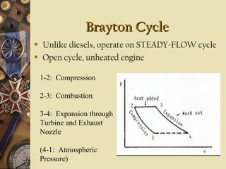
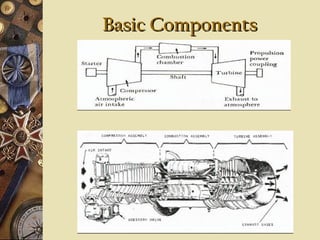

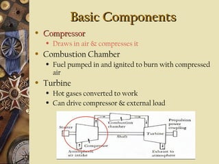
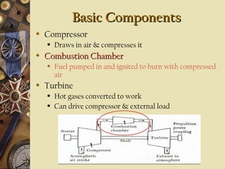
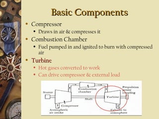
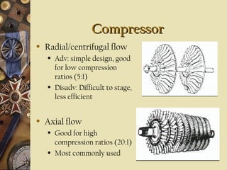
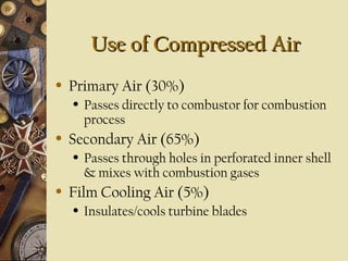
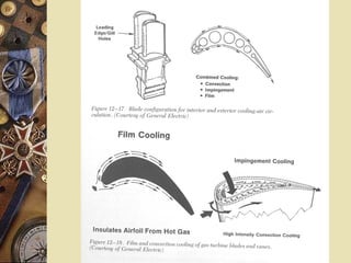
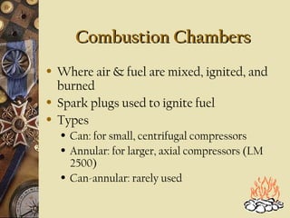
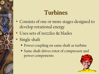
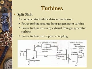
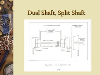
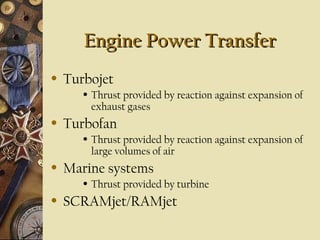


This document provides an overview of gas turbine theory and construction. It describes the basic components and thermodynamic processes of gas turbine engines, including the compressor, combustion chamber, turbine, and support systems. The Brayton cycle of open steady-flow operation is explained. Compression can be achieved through either radial or axial compressors. Fuel is ignited in the combustion chamber along with compressed air. The turbine converts the energy of combustion gases to rotational work to power the compressor and external loads. Support systems include air, fuel, lubrication, starting, and power transmission. Gas turbines are lighter and simpler than steam turbines.


