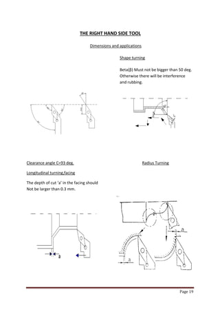
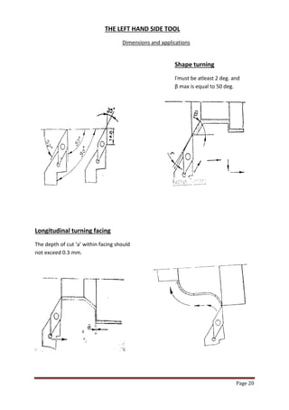
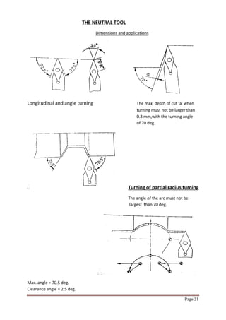
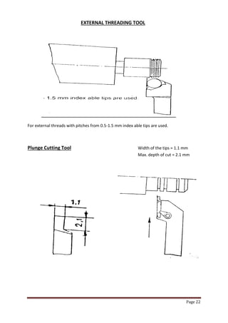
Page 1 
CNC TRAIN MASTER LATHE 
MODEL : CNC T – 100 (S) 
SUBMITTED TO :- SUBMITTED BY :- 
Prof. R.K. Mathur Rajeev Kumar Mandal Prof. O.P. Arora (H.O.D.) Kumar Gaurav DEPARTMENT OF MECHANICAL ENGINEERING FINAL YEAR (ME) BHAGWANT UNIVERSITY,AJMER RAJASTHAN
Page 2 
CAUTION 
1. Proper earth connection for CNC system and machine. 
User should be ensure proper earth connection to the 
equipements. 
2. Safety against input supply variation. 
The machine operates successfully with an input voltage of three 
Phase, 415 Volts +/- 10%, 50 Hz +/- 3% in case of variation in input 
supply voltage beyond the range, user is advised to use a suitable 
voltage stabilizing device like voltage stabilizer/ isolation 
transformer etc.
Page 3 
INDEX 
1. 
INTRODUCTION 
PAGE NO. 
1.1 
Develoment in metal cutting machine tools. 
4 
1.2 
An insight to CNC machine. 
4 
1.3 
CNC programming concept. 
5 
1.4 
Need for training in CNC. 
6 
1.5 
Advantages of CNC machines. 
6 
1.6 
Objectives of CNC machine training. 
6 
1.7 
Training method. 
7 
1.8 
Knowledge level of trainee. 
7 
2. 
SPECIFICATION AND FEATURES 
2.1 
Machine specifications. 
8 
2.2 
CNC system features. 
9 
3. 
MECHANICAL MACHINES DETAILS 
3.1 
Bed. 
10 
3.2 
Saddle and cross slide. 
10 
3.3 
Head stock. 
10 
3.4 
Tail stock. 
10 
3.5 
Tool turret. 
10 
3.6 
AC servo motor and drives. 
10 
4. 
OPERATING OF THE CNC SYSTEM 
4.1 
Putting machine in to operation. 
11 
4.2 
Feed ON control ON. 
11 
4.3 
Manual Movements. 
11 
4.4 
Reference Point approach. 
12 
5. 
PART PROGRAMMING 
5.1 
Coordinate system of CNC lathe. 
13 
5.2 
Programming methods. 
14 
5.3 
Preparatory function (G codes). 
17 
6. 
TOOL SETTING 
6.1 
Work piece reference point setting. 
18 
6.2 
Tool used. 
18 
7. 
PRACTICAL EXERCISES 
7.1 
Description of standard cycles. 
25 
8. 
Material needed for exercises. 
Annexture-1 
9. 
Selection of working parameters for cutting in a lathe. 
Annexture-2 
10. 
Electrical circuit diagrams. 
28
Page 4 
1. INTRODUCTION:- 
1.1 Development in metal cutting machine tools 
The general purpose machine tools like lathe, milling, boring and grinding machine etc, were being operated manually until 1950 components needed in large numbers were catered by automats and special purpose machines. There were no machines available for catering special purpose machines. There were no machine available for catering to the need of batch production, where the higher productivity of special purpose machines is combined with the ease for job change over as in general purpose machine. If the general purpose machines could be operated automatically, and at higher speed, without the operator actually turning the hand wheels it would improve the productivity of these machines. 
Such an automated machines is numerically controlled machine. Numerical control was developed in 1952 in USA and is commercially available since 1960s.In the last two decades rapid development and miniaturization in the field of electronics has made it possible to build controllers which can effectively control basic machine and also their peripheral devices reliably. 
Production of CNC machine is increasing proportion of CNC machines among the total metal cutting machine tools also growing rapidly. 
1.2 An insight to CNC machines 
In manufacturer of part on machine tools, the work piece shape and dimension are achieved either by moving the tool against a rotating work piece or by moving the work piece against a rotating tool. The movement of tool/work piece is commanded manually through the help of hand operated controls through associated kinematics arrangements. This procedure is to be repeated to every piece produced. The dimension obtained by the operator setting have to be verified by measurements and suitable correction made. To produce component of high accuracy the operator must have high skill. 
For complicated components the production cycle time be very large as each dimension must be measured and controlled. Components having special profiles which requires two or more slides to be moved simultaneously cannot be without special profile generation system. These factors are responsible for low production rates one conventional machines. 
In a CNC machine, the slide (axes) movement are controlled by AC servo motors. The main objective is to be able to reach a particular point accurately at the required speed. The spindle speed is selectable according to needs of a particular job.
Page 5 
The selection and usage of the right tool for each of the machining operation as to be repetitively done each work piece by the machine operator on conventional machine. On NC machine, presenting the correct tool to the work piece is automatic by automatic indexing (as commanded) of multi-tool turret or automatic tool changer. 
For achieving higher production rates, multiple activities of the machine such as speed changes, motions of various slides, presentation of the right tool should be made concurrent activities to the maximum extent. This would call for an ability for coordination and execution of multiple activities which is beyond the human capability. Electronics system use in the numerical control system can do this task with the required speed and precision with the development of the computer and microprocessors, the logic control functions are achieved through computers. Such systems are called CNC systems. 
1.3 CNC Programming Concepts 
CNC machines are controlled by CNC systems through the intermediate drive elements like motors, hydraulic actuators etc. in order to execute any particular task. CNC system required are technological like cutting speeds, feeds, dept of cut, type of tool and geometrical data like size and shope of the work piece to be cut. 
The information input to such CNC system is to be in standard format such as 
EIA-RS-274B for positioning and contouring control. 
The programming format contains the letter code for each word with a special out number of digits for each numerical information. The letter codes includes the program the number, preparatory command, direction and distance to be moved for each axis, co-ordinates of the center of segments of circles for profile contouring, the feed rate , the tool number, spindle speed and other miscellaneous functions. 
The general program format is : 
Wkord sequence : 
N…G…X…Y..Z..S..T..D…M.. 
N01G02X4Z8F42M2T6S4 
The details of the format used for the machine is explained in the chapter. 
5- part programming. 
Also refer programming manual of siemens 802s CNC system supplied with machine.
Page 6 
1.4 Need for training in CNC 
As explained in sections 2 and 3 CNC machines are fairly complex with many special functions added to those found on conventional machines to achieve better productivity through automation . these machines require instruction from the machine operator in a different medium then the conventional machines. To facilitate learning of operating CNC machines , it is essential to impart proper training and operating the machine with the prepared part program. 
For preparing the part program, the geometrical information from the part drawing has to be converted to the program format. To get familiarization in program preparation, confidence in its correctness and operation of the CNC machine through th program ‘hand on training ‘ is required. 
A full fledged CNC machine suitable for such a machine is very high making it consequently machine hour rates of such a machine is very high making it uneconomical for usage for training purpose. Any error by the learner in programming or operation of the machine will be expensive to correct as these could damage the machines apart from loss of production time. Trainer machines are built in such a way that there will be no damage to the machine even during the execution of faulty program. Thus the familiarly with CNC machining obtained by training machines will develop the confidence of the learner to a level where he can take up operation for machines. 
1.5 ` Advantages of CNC machines: 
1. High productivity for small/medium batch quantity manufacture. 
2. Requires no special tool setting. 
3. High repeatability and accuracy of work pieces. 
4. Reduction in rejections 
5. Can do complicated jobs not normally possible on conventional machines 
6. Reduction in operator fatigue 
7. Reduction in skill required for machining operations 
8. Ease of product change over 
9. Reduction in lead- time for staring production 
1.6 Objectives of CNC machine training 
1. To understand the operation of CNC control 
2. To operate CNC machines based on the theoretical instructions obtained 
3. Imparting the ability to write program for different parts, which are difficult to cut in conventional machines 
4. To edit and execute these programs for different parts, which are difficult to cut in conventional machines 
5. To reduce the difficulty for change over to production CNC machines 
6. To understand the requirements of other features and peripherals needed for optimum machining.
Page 7 
1.4 Training method 
Following sequential steps are generally to be followed to train person in 
CNC machine operation: 
1. Understanding specifications, features and functions of the machine 
2. Familiarisation with the machine features and control for operation of the machine 
3. Operating the machine through the CNC system 
4. Familiarization with part programming methods 
5. Took setting and tool selection 
6. Practical exercises 
1.8 Knowledge level of Trainee 
The trainee should have the ability to read simple drawings, do simple arithmetical calculations. He must be able to select the cutting parameters such as speed, feed etc. for the machining operations. 
The trainee should also be familiar with the use of a PC.
Page 8 
2. SPECIFICATIONS & FEATURES OF CNC T- 100 (S) LATHE 
CNC T-100 Train Master Lathe is designed for training of operators, methods engineers in CNC turning technology, turning operations involving plain turning taper turning , threading cutting , radius turning can be performed on this lathe. 
2.1 Machine Specifications 
1. Height of centres. mm 100 
2. Distance between centres. mm 310 
3. Swing over bed. mm 150 
4. Swing over cross slide mm 75 
5. Traverse of cross slide mm 75 
6. Max. turning Diameter mm 45 
7. Max. turning length mm 150 
8. Longitudinal traverse mm 180 
HEAD STOCK 
9. Hole through work spindle mm 16 
10. Spindle taper MT 
11. Type of drive AC variable 
12. Speed range (step less) RPM 50 – 3200 
13. Power Kw 0.75 
TAIL STOCK 
14. ` Spindle diameter mm 22 
15. Spindle taper MT 1 
16. Sleeve stroke mm 35 
FEED RATE 
17. Type of drive for both axis AC Servo motor 
18. Rapid traverse rate mm/min 700 
19. Programmable feed rate mm/min 0-0.700 
CNC System 
20. No. of axis 2 
21. Type Siemens 80 2C 
22. Weight of the machine (approx.) Kg. 250 
23. Tool (Turret model, Pragati make) BTP 40 
24. Tools stations Nos. 8 
25. Turret indexing position - 8 
26. Turning tool shank size mm 12*12
Page 9 
2.2 CNC system Features 
 Table top model suitable for machining of non ferrous material, 
however light cut of 0.2 mm on diameter without coolant can be 
taken on mild steel. 
 Step less AC drive. 
 Antifriction preloaded high precision spindle bearing. 
 Precision slide motion through for recirculating ball screw/ nut 
arrangement for longitudinal and cross direction. 
 Number of axes 2. 
 Incremental and continuous JOG. 
 Reference point approach. 
 MDI/SINGLE BLOCK/AUTOMATIC execution. 
 Axis homing. 
 Feed hold. 
 Feed rate over ride 0 to 120%. 
 Standard G&M codes as per ISO. 
 Linear and circular interpolation. 
 Dwell time. 
 Rapid feed rate 700mm/min. 
 Thread cutting. 
 Turning and threading cycles. 
 Inch/metric mode of input. 
 Feed programmable in per minutes and per revolution. 
 Zero off sets. 
 Tool nose radius compensation. 
 Full screen editor. 
 Cursor motions to selected block delete. 
 Program handling function like dir.del.copy.remane. 
 Block move, copy and delete. 
 Graphic simulation. 
 Block skip. 
 MPG. 
 A/C Panel
Page 10 
3. Mechanical Machine Details 
The mechanical machine has the following: 
1. Bed 
2. Saddle and cross slide 
3. Head stock 
4. Tail stock 
5. Tool turret 
6. Axes drive system. 
7. Spindle drive system. 
3.1 BED 
Bed is built with projected high quality cast iron and has V and flat 
guideways & without side keeper plate. The head stock is mounted 
on the left hand side of the bed. The bed is fixed on the base plate. 
3.2 SADDLE AND CROSS SLIDE 
The saddle is fitted over the bed guide ways using two keeper plates 
lined with Turcite. The saddle is moved over the bed using the Z-axis 
ball screw nut mechanism. The feed movement is obtained by a Stepper 
motor and ball screw. It also houses the ball screw connected to the X 
axis stepper motor through a timing belt. The cross slide carries the 
tool turret on which the external turning tools and boring tools are mounted. 
3.3 HEAD STOCK 
The head stock contains the spindle of the machine. The spindle has a 
MT2 taper and a adopter flange can be fixed for mounting three or four 
jaw chucks. 
3.3 TAIL STOCK 
The tail stock can be fixed at any point along the bed guide ways using 
a keeper plate. The tail stock has a sleeve with MT1 taper and can be 
moved in or out using the small hand wheel. This can also be used for 
mounting drills and centering bits. 
3.5 TOOL TURRET 
The auto tool turret having 4 internal and 4 external tools is mounted in 
the cross sleeve. The turret is in directional drives in 24V DC motor. 
3.6 MOTOR DRIVE 
Stepper motor and drive are used in both the axes of siemens make. 
Spindle drives with AC servo motor.
Page 11 
4. OPERATION OF THE SYSTEM 
In the following pages the main operations are described. The operator is 
advised to study earlier chapters regarding the location of the control and description of the control and be familiar with all controls to prepare for 
this section. 
To prepare part programme vis manual input mode observe guidelines of the programming and operating instructions of the CNC system manual supplied along with this manual. 
Refer to appropriate operating manual of the CNC system supplied with the machine for the specific operation of the system control. 
4.1 PUTTING MACHINE INTO OPERATION: 
- Keep the emergency push button athe conrrol post pressed This - latches on its own and will remain closed. - Switch on the man incoming single phase supply. - Turn the mains switch at the control post to ON position(1S1). - Mains ON indication light on control post will be ON. - The emergency push button is now released and machine is ready for operation. 
4.2 Feed ON/Control ON 
Preconditions: 
- Emergency push button EPM is not pressed. 
- Light LTO is ON. 
START: 
- Press control ON push on machine control panel. 
- Relay CRI will be ON. 
- Message “NOT READY ON CNC SCREEN WILL GO AND AXES 
DRIVE WILL BE ENABLES.” 
4.3 Manual movement: a. Job mode Preconditions: 
- Jog mode is selected on CRT 
- Control/Feed ON 
- Axes drives are healthy. 
Note :- TOOL TURRET CAN BE INDEXED BY ONE POSITION BY PRESSING 
TURRET INDEX KEY.
Page 12 
Start: 
A) 
- Select feed rate by feed over-ride switch. 
- To move the X-axis slide towards inward,press - X key and 
towards operator side,press + X key. - Rapid jog movement is effective by pressing two keys 
simultaneously i.e. rapid movement key alongwith respective jog 
movement key. 
- To move Z axis slide towards left side, press –Z key and to move 
- Towards right side,press +Z key. 
B) Incremental mode : Preconditions ` - Select increment jog mode. - Select incremental mode on CRT as per requirement i.e. inc 1 or Inc 10 or inc 100. - Slide will move 0.001,0.01 and 0.100 mm respectively by selecting inc1, inc10 and 100. - Inc 1000 and inc 10000 are not effective. 
C) Manual pulse generators MPG - Select MPG on CRT. - Manual pulse generator is provided for X and Z axis Slides depending upon selection and correction factor. Individual respective slide will move by the selected inc 1 or 10 per pulse desired direction. 
4.4 Reference point approach : - Control/Feed ON - Drive for axes are enable i.e. CR1+ - Home mode selected on CRT, X and Z soft keys starts blinking. - Feed over-ride switch not at zero position. X-Axis - Select X axis by pressing +X key. - Slide X moves to reference position. Z-Axis - Select Z axis by pressing +Z key. - Slide Z mode to reference position, now X and Z axes are reference. 
TOOL TURRET REFERENCE Press TURRET REFERENCE Key Turret moves to reference position.
Page 13 
PART PROGRAMMING 
As explained in chapter 1.3 the part program provides the instructions to the CNC 
control the execute the machine operations.The coordinate system of the machine has been explained is in the chapter.The programming methods program structure and explanation of each operating codes have also been provided. 
5.1 Coordinate system of CNC lathe 
The information “move the longitudinal slide in the head stock direction” is a very long one. besides, in each language, it would be different that’s why the traverse path movements in machine tools are described within the coordinate system. Coordinate system on a NC lathe is shown below. 
Z-axis - Axis parallel to the turning axis 
X- axis - Axis perpendicular to the turning axis 
-Z movement - Movement of the longitudinal slide towards the 
direction of the head stock. 
+Z movement - Movement of the longitudinal slide away from 
the head stock. 
-X movement - Movement of the cross slide towards the spindle 
axis. 
+X movement - Movement of the cross slide away from the spindle 
axis.
Page 14 
5.2 Programming methods 
There are two method to describe the path of motion in a CNC machine: 
1.Absolute programming method. 
2.Incremental programming method. 
In absolute programming method,the next point on the work piece is Taken as a reference or zero point and all the other dimensions are represented with respect to that point. 
In incremental programming method,the next point dimension in each block is referred with respect to the final point on the previous block. 
The system of dimensioning in each method is shown in the Illustrations. 
ABSOLUTE SYSTEM OF DIMENSIONING 
INCREMENTAL SYSTEM OF DIMENSIONING
Page 15 
Programming method comparison 
Absolute system Incremental system 
The path information given to the turning The zero reference point for Tools is always calculated from a definite each path information is the Starting point. Current position of the tool Itself. 
Path X Z Path X Z 
A -3 0 A -3 0 
B -3 -2.5 B 0 2.5 
C -2 -2.5 C 1 0 
D -2 -4 D 0 -1.5 
E 0 -0 E 2 -2 
Only point 0 is the reference Point 0,1,2,3,4 are all new reference point.
Page 16 
Absolute system Incremental system 
If you have to change the position of a If you have to change position Point all other points still remain of one point,all the Following Unchanged. Ones will have to be changed As well. 
Point 1 has to be changed to point 1 since point 1 was changed, the The description for point 2 and 3 description for point 2&3 also Changes. remains unchanged. 
Path X Z Path X Z 
A -1 -1 A -1 1 
B -1 -2.5 B 0 1.5 
C 0 -2.5 C 1 0 
D -1.5 -0.5 D -1.5 -0.5 
E 0 -2.5 E 1 0 
Effective until cancelled by G00,G01
Page 17 
5.3 PREPARATORY FUNCTION (G FUNCTION) 
G code Table : 
G CODE 
FUNCTION 
G00 
Positioning (Rapid traverse) 
G01 
Linear interpolation (Feed) 
G02 
Circular interpolation CW 
G03 
Circular interpolation CCW 
G04 
Dwell time 
G9 
Non-model exact stop 
G17 
(Required for center drilling) 
G18 
Z/X Plane selection 
G22 
Radius input 
G23 
Diameter input 
G25 
Lower spindle speed limit 
G26 
Upper spindle speed limit 
G40 
Tool radius compensation off 
G41 
Tool radius compensation left of cotour 
G42 
Tool radius compensation right of cotour 
G53 
Non-model suppression of settable of zero offset 
G54 
1st settable zero offset 
G55 
2nd settable zero offset 
G56 
3rd settable zero offset 
G57 
4th settable zero offset 
G60 
Exact positioning 
G64 
Contineous path mode 
G70 
Dimensions in inches 
G71 
Dimensions in metric values 
G74 
Reference point approach 
G75 
Fixed point approach 
G90 
Absolute dimensions 
G91 
Incremental dimensions 
G94 
Feed rate F in mm/min. 
G95 
Feed rate F in mm/rev of spindle 
G96 
Constant cutting speed for turning on (F in mm/rev,S in m/min) 
G97 
Constant cutting speed of turning off 
G158 
Programmable offset 
G450 
Transition circle 
G451 
Point of intersection 
G500 
Settable zero offset off 
G601 
Exact positioning window fine for G60,G9 
G602 
Exact positioning window coarse for G60,G9
Page 18 
6. Tool Setting 
6.1 Work piece reference point setting 
Switch the spindle on set the spindle RPM ` By joggong the X and Z axis bring the tool to the desired position (i.e. when the tool just scratches the work piece). Using PRESET mode preset X and Z axis value to zero. 
6.2 Tool used on this lathe 
Depending upon the operation and configuration of the components 
Following tools can be used on the machine. 
1. Right hand side tool 
2. Left hand side tool 
3. Neutral tool 
4. External threading tool 
5. External grooving tool 
6. Parting off tool 
7. Internal threading tool 
8. Boring tool 
The detailed application of the above tools is given in the following 
pages.
Page 19 
THE RIGHT HAND SIDE TOOL 
Dimensions and applications 
Shape turning 
Beta(β) Must not be bigger than 50 deg. 
Otherwise there will be interference 
and rubbing. 
Clearance angle C=93 deg. Radius Turning 
Longitudinal turning,facing 
The depth of cut ‘a’ in the facing should Not be larger than 0.3 mm.
Page 20 
THE LEFT HAND SIDE TOOL 
Dimensions and applications 
Shape turning 
Γmust be atleast 2 deg. and β max is equal to 50 deg. 
Longitudinal turning facing 
The depth of cut ‘a’ within facing should not exceed 0.3 mm.
Page 21 
THE NEUTRAL TOOL 
Dimensions and applications 
Longitudinal and angle turning The max. depth of cut ‘a’ when turning must not be larger than 0.3 mm,with the turning angle of 70 deg. Turning of partial radius turning 
The angle of the arc must not be largest than 70 deg. 
Max. angle = 70.5 deg. Clearance angle = 2.5 deg.
Page 22 
EXTERNAL THREADING TOOL 
For external threads with pitches from 0.5-1.5 mm index able tips are used. 
Plunge Cutting Tool Width of the tips = 1.1 mm Max. depth of cut = 2.1 mm
Page 23 
PARTING – OFF TOOL HSS 
INTERNAL THREADING TOOL 
Internal threading can be done on jobs with minor thread diameter of 20 mm or more. Inexorable tips of pitches from 0.5 to 1 mm can be used. 
Note : Alternatively, brazed internal threading tools may be used.
Page 24 
INSIDE TURNING TOOL 
Inside turning (Boring) can be performed on jobs with internal diameter more than 16 mm. 
Dimensions : Max. clearance angle when turning inwards = 90 deg. Max. depth of cut (Facing) is 0.3 mm.
Page 25 
7. Practical Exercises 
Please refer chapter 9 of programming manual of SIEMENS 802S CNC 
System supplied with the machine, containing following standards cycles: 
7-1 Drilling, Spot-facing. - LCYC82 
7-2 Deep hole drilling - LCYC83 
7-3 Tapping with compensation chuck. - LCYC840 
7-4 Boring. - LCYC85 
7-5 Recess. - LCYC93 
7-6 Undercut (Forms E and F to DIN) - LCYC94 
7-7 Stock removal with relief cuts. - LCYC95 
7-8 Thread cutting. - LCYC97
Page 26 
Annexure – 1 
Material needed for training 
SL. 
No. 
Description 
Specification 
No. off 
Remarks 
1. 
Raw material 
A1 rod 
IS D734-1975 Dsgn,22588 
45*65mm & dia 45*30mm 
2 
2. 
Raw material 
Mild steel 
IS 1732-1971 
45*65mm 
2 
3. 
Chuck 
3 Jaw self centering chuck 
1 
4. 
Tools 
Rt. Hand turning tool with inserts 
1 
Lt. Hand turning tool with inserts 
1 
Neutral tirning tool with insert 
1 
Parting off tool 
1 
External thread cutting tool 
1 
Internal thread cutting tool 
1 
Boring tool with inserts 
1 
5. 
Standard tools 
Spanners 7*8,8*10,13*17 Allen key 
3,4,5,6 
1 set
Page 27 
Annexure – 2 
Selection of working parameters for cutting in a lathe 
1. Cutting speed (Vs) 
Vs (M/min)= ( ) ( ) ⁄ 
d = Diameter of the work piece 
s = Spindle speed (RPM) 
Cutting speed to be used in this lathe 
For turning : 150 to 200 M/min. 
For parting off : 60 to 80 M/min. 
2. Calculation of spindle speed 
S(Revolution/min)= ( ) ⁄ ( ) 
3. Cutting of feed F 
F (mm/min.)= S(Rev/Min.) * F (mm/Rev) 
For normally used for turning : 0.02 to 0.1 mm/Rev. 
For used for parting off : 0.01 to 0.02 mm/Rev.
Page 28 
10. Electrical circuit diagrams.
Page 29
Page 30
Page 31
Page 32
Page 33
Page 34
Page 35
Page 36
Page 37
Page 38

Cnc t 100

  • 1.
    Page 1 CNCTRAIN MASTER LATHE MODEL : CNC T – 100 (S) SUBMITTED TO :- SUBMITTED BY :- Prof. R.K. Mathur Rajeev Kumar Mandal Prof. O.P. Arora (H.O.D.) Kumar Gaurav DEPARTMENT OF MECHANICAL ENGINEERING FINAL YEAR (ME) BHAGWANT UNIVERSITY,AJMER RAJASTHAN
  • 2.
    Page 2 CAUTION 1. Proper earth connection for CNC system and machine. User should be ensure proper earth connection to the equipements. 2. Safety against input supply variation. The machine operates successfully with an input voltage of three Phase, 415 Volts +/- 10%, 50 Hz +/- 3% in case of variation in input supply voltage beyond the range, user is advised to use a suitable voltage stabilizing device like voltage stabilizer/ isolation transformer etc.
  • 3.
    Page 3 INDEX 1. INTRODUCTION PAGE NO. 1.1 Develoment in metal cutting machine tools. 4 1.2 An insight to CNC machine. 4 1.3 CNC programming concept. 5 1.4 Need for training in CNC. 6 1.5 Advantages of CNC machines. 6 1.6 Objectives of CNC machine training. 6 1.7 Training method. 7 1.8 Knowledge level of trainee. 7 2. SPECIFICATION AND FEATURES 2.1 Machine specifications. 8 2.2 CNC system features. 9 3. MECHANICAL MACHINES DETAILS 3.1 Bed. 10 3.2 Saddle and cross slide. 10 3.3 Head stock. 10 3.4 Tail stock. 10 3.5 Tool turret. 10 3.6 AC servo motor and drives. 10 4. OPERATING OF THE CNC SYSTEM 4.1 Putting machine in to operation. 11 4.2 Feed ON control ON. 11 4.3 Manual Movements. 11 4.4 Reference Point approach. 12 5. PART PROGRAMMING 5.1 Coordinate system of CNC lathe. 13 5.2 Programming methods. 14 5.3 Preparatory function (G codes). 17 6. TOOL SETTING 6.1 Work piece reference point setting. 18 6.2 Tool used. 18 7. PRACTICAL EXERCISES 7.1 Description of standard cycles. 25 8. Material needed for exercises. Annexture-1 9. Selection of working parameters for cutting in a lathe. Annexture-2 10. Electrical circuit diagrams. 28
  • 4.
    Page 4 1.INTRODUCTION:- 1.1 Development in metal cutting machine tools The general purpose machine tools like lathe, milling, boring and grinding machine etc, were being operated manually until 1950 components needed in large numbers were catered by automats and special purpose machines. There were no machines available for catering special purpose machines. There were no machine available for catering to the need of batch production, where the higher productivity of special purpose machines is combined with the ease for job change over as in general purpose machine. If the general purpose machines could be operated automatically, and at higher speed, without the operator actually turning the hand wheels it would improve the productivity of these machines. Such an automated machines is numerically controlled machine. Numerical control was developed in 1952 in USA and is commercially available since 1960s.In the last two decades rapid development and miniaturization in the field of electronics has made it possible to build controllers which can effectively control basic machine and also their peripheral devices reliably. Production of CNC machine is increasing proportion of CNC machines among the total metal cutting machine tools also growing rapidly. 1.2 An insight to CNC machines In manufacturer of part on machine tools, the work piece shape and dimension are achieved either by moving the tool against a rotating work piece or by moving the work piece against a rotating tool. The movement of tool/work piece is commanded manually through the help of hand operated controls through associated kinematics arrangements. This procedure is to be repeated to every piece produced. The dimension obtained by the operator setting have to be verified by measurements and suitable correction made. To produce component of high accuracy the operator must have high skill. For complicated components the production cycle time be very large as each dimension must be measured and controlled. Components having special profiles which requires two or more slides to be moved simultaneously cannot be without special profile generation system. These factors are responsible for low production rates one conventional machines. In a CNC machine, the slide (axes) movement are controlled by AC servo motors. The main objective is to be able to reach a particular point accurately at the required speed. The spindle speed is selectable according to needs of a particular job.
  • 5.
    Page 5 Theselection and usage of the right tool for each of the machining operation as to be repetitively done each work piece by the machine operator on conventional machine. On NC machine, presenting the correct tool to the work piece is automatic by automatic indexing (as commanded) of multi-tool turret or automatic tool changer. For achieving higher production rates, multiple activities of the machine such as speed changes, motions of various slides, presentation of the right tool should be made concurrent activities to the maximum extent. This would call for an ability for coordination and execution of multiple activities which is beyond the human capability. Electronics system use in the numerical control system can do this task with the required speed and precision with the development of the computer and microprocessors, the logic control functions are achieved through computers. Such systems are called CNC systems. 1.3 CNC Programming Concepts CNC machines are controlled by CNC systems through the intermediate drive elements like motors, hydraulic actuators etc. in order to execute any particular task. CNC system required are technological like cutting speeds, feeds, dept of cut, type of tool and geometrical data like size and shope of the work piece to be cut. The information input to such CNC system is to be in standard format such as EIA-RS-274B for positioning and contouring control. The programming format contains the letter code for each word with a special out number of digits for each numerical information. The letter codes includes the program the number, preparatory command, direction and distance to be moved for each axis, co-ordinates of the center of segments of circles for profile contouring, the feed rate , the tool number, spindle speed and other miscellaneous functions. The general program format is : Wkord sequence : N…G…X…Y..Z..S..T..D…M.. N01G02X4Z8F42M2T6S4 The details of the format used for the machine is explained in the chapter. 5- part programming. Also refer programming manual of siemens 802s CNC system supplied with machine.
  • 6.
    Page 6 1.4Need for training in CNC As explained in sections 2 and 3 CNC machines are fairly complex with many special functions added to those found on conventional machines to achieve better productivity through automation . these machines require instruction from the machine operator in a different medium then the conventional machines. To facilitate learning of operating CNC machines , it is essential to impart proper training and operating the machine with the prepared part program. For preparing the part program, the geometrical information from the part drawing has to be converted to the program format. To get familiarization in program preparation, confidence in its correctness and operation of the CNC machine through th program ‘hand on training ‘ is required. A full fledged CNC machine suitable for such a machine is very high making it consequently machine hour rates of such a machine is very high making it uneconomical for usage for training purpose. Any error by the learner in programming or operation of the machine will be expensive to correct as these could damage the machines apart from loss of production time. Trainer machines are built in such a way that there will be no damage to the machine even during the execution of faulty program. Thus the familiarly with CNC machining obtained by training machines will develop the confidence of the learner to a level where he can take up operation for machines. 1.5 ` Advantages of CNC machines: 1. High productivity for small/medium batch quantity manufacture. 2. Requires no special tool setting. 3. High repeatability and accuracy of work pieces. 4. Reduction in rejections 5. Can do complicated jobs not normally possible on conventional machines 6. Reduction in operator fatigue 7. Reduction in skill required for machining operations 8. Ease of product change over 9. Reduction in lead- time for staring production 1.6 Objectives of CNC machine training 1. To understand the operation of CNC control 2. To operate CNC machines based on the theoretical instructions obtained 3. Imparting the ability to write program for different parts, which are difficult to cut in conventional machines 4. To edit and execute these programs for different parts, which are difficult to cut in conventional machines 5. To reduce the difficulty for change over to production CNC machines 6. To understand the requirements of other features and peripherals needed for optimum machining.
  • 7.
    Page 7 1.4Training method Following sequential steps are generally to be followed to train person in CNC machine operation: 1. Understanding specifications, features and functions of the machine 2. Familiarisation with the machine features and control for operation of the machine 3. Operating the machine through the CNC system 4. Familiarization with part programming methods 5. Took setting and tool selection 6. Practical exercises 1.8 Knowledge level of Trainee The trainee should have the ability to read simple drawings, do simple arithmetical calculations. He must be able to select the cutting parameters such as speed, feed etc. for the machining operations. The trainee should also be familiar with the use of a PC.
  • 8.
    Page 8 2.SPECIFICATIONS & FEATURES OF CNC T- 100 (S) LATHE CNC T-100 Train Master Lathe is designed for training of operators, methods engineers in CNC turning technology, turning operations involving plain turning taper turning , threading cutting , radius turning can be performed on this lathe. 2.1 Machine Specifications 1. Height of centres. mm 100 2. Distance between centres. mm 310 3. Swing over bed. mm 150 4. Swing over cross slide mm 75 5. Traverse of cross slide mm 75 6. Max. turning Diameter mm 45 7. Max. turning length mm 150 8. Longitudinal traverse mm 180 HEAD STOCK 9. Hole through work spindle mm 16 10. Spindle taper MT 11. Type of drive AC variable 12. Speed range (step less) RPM 50 – 3200 13. Power Kw 0.75 TAIL STOCK 14. ` Spindle diameter mm 22 15. Spindle taper MT 1 16. Sleeve stroke mm 35 FEED RATE 17. Type of drive for both axis AC Servo motor 18. Rapid traverse rate mm/min 700 19. Programmable feed rate mm/min 0-0.700 CNC System 20. No. of axis 2 21. Type Siemens 80 2C 22. Weight of the machine (approx.) Kg. 250 23. Tool (Turret model, Pragati make) BTP 40 24. Tools stations Nos. 8 25. Turret indexing position - 8 26. Turning tool shank size mm 12*12
  • 9.
    Page 9 2.2CNC system Features  Table top model suitable for machining of non ferrous material, however light cut of 0.2 mm on diameter without coolant can be taken on mild steel.  Step less AC drive.  Antifriction preloaded high precision spindle bearing.  Precision slide motion through for recirculating ball screw/ nut arrangement for longitudinal and cross direction.  Number of axes 2.  Incremental and continuous JOG.  Reference point approach.  MDI/SINGLE BLOCK/AUTOMATIC execution.  Axis homing.  Feed hold.  Feed rate over ride 0 to 120%.  Standard G&M codes as per ISO.  Linear and circular interpolation.  Dwell time.  Rapid feed rate 700mm/min.  Thread cutting.  Turning and threading cycles.  Inch/metric mode of input.  Feed programmable in per minutes and per revolution.  Zero off sets.  Tool nose radius compensation.  Full screen editor.  Cursor motions to selected block delete.  Program handling function like dir.del.copy.remane.  Block move, copy and delete.  Graphic simulation.  Block skip.  MPG.  A/C Panel
  • 10.
    Page 10 3.Mechanical Machine Details The mechanical machine has the following: 1. Bed 2. Saddle and cross slide 3. Head stock 4. Tail stock 5. Tool turret 6. Axes drive system. 7. Spindle drive system. 3.1 BED Bed is built with projected high quality cast iron and has V and flat guideways & without side keeper plate. The head stock is mounted on the left hand side of the bed. The bed is fixed on the base plate. 3.2 SADDLE AND CROSS SLIDE The saddle is fitted over the bed guide ways using two keeper plates lined with Turcite. The saddle is moved over the bed using the Z-axis ball screw nut mechanism. The feed movement is obtained by a Stepper motor and ball screw. It also houses the ball screw connected to the X axis stepper motor through a timing belt. The cross slide carries the tool turret on which the external turning tools and boring tools are mounted. 3.3 HEAD STOCK The head stock contains the spindle of the machine. The spindle has a MT2 taper and a adopter flange can be fixed for mounting three or four jaw chucks. 3.3 TAIL STOCK The tail stock can be fixed at any point along the bed guide ways using a keeper plate. The tail stock has a sleeve with MT1 taper and can be moved in or out using the small hand wheel. This can also be used for mounting drills and centering bits. 3.5 TOOL TURRET The auto tool turret having 4 internal and 4 external tools is mounted in the cross sleeve. The turret is in directional drives in 24V DC motor. 3.6 MOTOR DRIVE Stepper motor and drive are used in both the axes of siemens make. Spindle drives with AC servo motor.
  • 11.
    Page 11 4.OPERATION OF THE SYSTEM In the following pages the main operations are described. The operator is advised to study earlier chapters regarding the location of the control and description of the control and be familiar with all controls to prepare for this section. To prepare part programme vis manual input mode observe guidelines of the programming and operating instructions of the CNC system manual supplied along with this manual. Refer to appropriate operating manual of the CNC system supplied with the machine for the specific operation of the system control. 4.1 PUTTING MACHINE INTO OPERATION: - Keep the emergency push button athe conrrol post pressed This - latches on its own and will remain closed. - Switch on the man incoming single phase supply. - Turn the mains switch at the control post to ON position(1S1). - Mains ON indication light on control post will be ON. - The emergency push button is now released and machine is ready for operation. 4.2 Feed ON/Control ON Preconditions: - Emergency push button EPM is not pressed. - Light LTO is ON. START: - Press control ON push on machine control panel. - Relay CRI will be ON. - Message “NOT READY ON CNC SCREEN WILL GO AND AXES DRIVE WILL BE ENABLES.” 4.3 Manual movement: a. Job mode Preconditions: - Jog mode is selected on CRT - Control/Feed ON - Axes drives are healthy. Note :- TOOL TURRET CAN BE INDEXED BY ONE POSITION BY PRESSING TURRET INDEX KEY.
  • 12.
    Page 12 Start: A) - Select feed rate by feed over-ride switch. - To move the X-axis slide towards inward,press - X key and towards operator side,press + X key. - Rapid jog movement is effective by pressing two keys simultaneously i.e. rapid movement key alongwith respective jog movement key. - To move Z axis slide towards left side, press –Z key and to move - Towards right side,press +Z key. B) Incremental mode : Preconditions ` - Select increment jog mode. - Select incremental mode on CRT as per requirement i.e. inc 1 or Inc 10 or inc 100. - Slide will move 0.001,0.01 and 0.100 mm respectively by selecting inc1, inc10 and 100. - Inc 1000 and inc 10000 are not effective. C) Manual pulse generators MPG - Select MPG on CRT. - Manual pulse generator is provided for X and Z axis Slides depending upon selection and correction factor. Individual respective slide will move by the selected inc 1 or 10 per pulse desired direction. 4.4 Reference point approach : - Control/Feed ON - Drive for axes are enable i.e. CR1+ - Home mode selected on CRT, X and Z soft keys starts blinking. - Feed over-ride switch not at zero position. X-Axis - Select X axis by pressing +X key. - Slide X moves to reference position. Z-Axis - Select Z axis by pressing +Z key. - Slide Z mode to reference position, now X and Z axes are reference. TOOL TURRET REFERENCE Press TURRET REFERENCE Key Turret moves to reference position.
  • 13.
    Page 13 PARTPROGRAMMING As explained in chapter 1.3 the part program provides the instructions to the CNC control the execute the machine operations.The coordinate system of the machine has been explained is in the chapter.The programming methods program structure and explanation of each operating codes have also been provided. 5.1 Coordinate system of CNC lathe The information “move the longitudinal slide in the head stock direction” is a very long one. besides, in each language, it would be different that’s why the traverse path movements in machine tools are described within the coordinate system. Coordinate system on a NC lathe is shown below. Z-axis - Axis parallel to the turning axis X- axis - Axis perpendicular to the turning axis -Z movement - Movement of the longitudinal slide towards the direction of the head stock. +Z movement - Movement of the longitudinal slide away from the head stock. -X movement - Movement of the cross slide towards the spindle axis. +X movement - Movement of the cross slide away from the spindle axis.
  • 14.
    Page 14 5.2Programming methods There are two method to describe the path of motion in a CNC machine: 1.Absolute programming method. 2.Incremental programming method. In absolute programming method,the next point on the work piece is Taken as a reference or zero point and all the other dimensions are represented with respect to that point. In incremental programming method,the next point dimension in each block is referred with respect to the final point on the previous block. The system of dimensioning in each method is shown in the Illustrations. ABSOLUTE SYSTEM OF DIMENSIONING INCREMENTAL SYSTEM OF DIMENSIONING
  • 15.
    Page 15 Programmingmethod comparison Absolute system Incremental system The path information given to the turning The zero reference point for Tools is always calculated from a definite each path information is the Starting point. Current position of the tool Itself. Path X Z Path X Z A -3 0 A -3 0 B -3 -2.5 B 0 2.5 C -2 -2.5 C 1 0 D -2 -4 D 0 -1.5 E 0 -0 E 2 -2 Only point 0 is the reference Point 0,1,2,3,4 are all new reference point.
  • 16.
    Page 16 Absolutesystem Incremental system If you have to change the position of a If you have to change position Point all other points still remain of one point,all the Following Unchanged. Ones will have to be changed As well. Point 1 has to be changed to point 1 since point 1 was changed, the The description for point 2 and 3 description for point 2&3 also Changes. remains unchanged. Path X Z Path X Z A -1 -1 A -1 1 B -1 -2.5 B 0 1.5 C 0 -2.5 C 1 0 D -1.5 -0.5 D -1.5 -0.5 E 0 -2.5 E 1 0 Effective until cancelled by G00,G01
  • 17.
    Page 17 5.3PREPARATORY FUNCTION (G FUNCTION) G code Table : G CODE FUNCTION G00 Positioning (Rapid traverse) G01 Linear interpolation (Feed) G02 Circular interpolation CW G03 Circular interpolation CCW G04 Dwell time G9 Non-model exact stop G17 (Required for center drilling) G18 Z/X Plane selection G22 Radius input G23 Diameter input G25 Lower spindle speed limit G26 Upper spindle speed limit G40 Tool radius compensation off G41 Tool radius compensation left of cotour G42 Tool radius compensation right of cotour G53 Non-model suppression of settable of zero offset G54 1st settable zero offset G55 2nd settable zero offset G56 3rd settable zero offset G57 4th settable zero offset G60 Exact positioning G64 Contineous path mode G70 Dimensions in inches G71 Dimensions in metric values G74 Reference point approach G75 Fixed point approach G90 Absolute dimensions G91 Incremental dimensions G94 Feed rate F in mm/min. G95 Feed rate F in mm/rev of spindle G96 Constant cutting speed for turning on (F in mm/rev,S in m/min) G97 Constant cutting speed of turning off G158 Programmable offset G450 Transition circle G451 Point of intersection G500 Settable zero offset off G601 Exact positioning window fine for G60,G9 G602 Exact positioning window coarse for G60,G9
  • 18.
    Page 18 6.Tool Setting 6.1 Work piece reference point setting Switch the spindle on set the spindle RPM ` By joggong the X and Z axis bring the tool to the desired position (i.e. when the tool just scratches the work piece). Using PRESET mode preset X and Z axis value to zero. 6.2 Tool used on this lathe Depending upon the operation and configuration of the components Following tools can be used on the machine. 1. Right hand side tool 2. Left hand side tool 3. Neutral tool 4. External threading tool 5. External grooving tool 6. Parting off tool 7. Internal threading tool 8. Boring tool The detailed application of the above tools is given in the following pages.
  • 19.
    Page 19 THERIGHT HAND SIDE TOOL Dimensions and applications Shape turning Beta(β) Must not be bigger than 50 deg. Otherwise there will be interference and rubbing. Clearance angle C=93 deg. Radius Turning Longitudinal turning,facing The depth of cut ‘a’ in the facing should Not be larger than 0.3 mm.
  • 20.
    Page 20 THELEFT HAND SIDE TOOL Dimensions and applications Shape turning Γmust be atleast 2 deg. and β max is equal to 50 deg. Longitudinal turning facing The depth of cut ‘a’ within facing should not exceed 0.3 mm.
  • 21.
    Page 21 THENEUTRAL TOOL Dimensions and applications Longitudinal and angle turning The max. depth of cut ‘a’ when turning must not be larger than 0.3 mm,with the turning angle of 70 deg. Turning of partial radius turning The angle of the arc must not be largest than 70 deg. Max. angle = 70.5 deg. Clearance angle = 2.5 deg.
  • 22.
    Page 22 EXTERNALTHREADING TOOL For external threads with pitches from 0.5-1.5 mm index able tips are used. Plunge Cutting Tool Width of the tips = 1.1 mm Max. depth of cut = 2.1 mm
  • 23.
    Page 23 PARTING– OFF TOOL HSS INTERNAL THREADING TOOL Internal threading can be done on jobs with minor thread diameter of 20 mm or more. Inexorable tips of pitches from 0.5 to 1 mm can be used. Note : Alternatively, brazed internal threading tools may be used.
  • 24.
    Page 24 INSIDETURNING TOOL Inside turning (Boring) can be performed on jobs with internal diameter more than 16 mm. Dimensions : Max. clearance angle when turning inwards = 90 deg. Max. depth of cut (Facing) is 0.3 mm.
  • 25.
    Page 25 7.Practical Exercises Please refer chapter 9 of programming manual of SIEMENS 802S CNC System supplied with the machine, containing following standards cycles: 7-1 Drilling, Spot-facing. - LCYC82 7-2 Deep hole drilling - LCYC83 7-3 Tapping with compensation chuck. - LCYC840 7-4 Boring. - LCYC85 7-5 Recess. - LCYC93 7-6 Undercut (Forms E and F to DIN) - LCYC94 7-7 Stock removal with relief cuts. - LCYC95 7-8 Thread cutting. - LCYC97
  • 26.
    Page 26 Annexure– 1 Material needed for training SL. No. Description Specification No. off Remarks 1. Raw material A1 rod IS D734-1975 Dsgn,22588 45*65mm & dia 45*30mm 2 2. Raw material Mild steel IS 1732-1971 45*65mm 2 3. Chuck 3 Jaw self centering chuck 1 4. Tools Rt. Hand turning tool with inserts 1 Lt. Hand turning tool with inserts 1 Neutral tirning tool with insert 1 Parting off tool 1 External thread cutting tool 1 Internal thread cutting tool 1 Boring tool with inserts 1 5. Standard tools Spanners 7*8,8*10,13*17 Allen key 3,4,5,6 1 set
  • 27.
    Page 27 Annexure– 2 Selection of working parameters for cutting in a lathe 1. Cutting speed (Vs) Vs (M/min)= ( ) ( ) ⁄ d = Diameter of the work piece s = Spindle speed (RPM) Cutting speed to be used in this lathe For turning : 150 to 200 M/min. For parting off : 60 to 80 M/min. 2. Calculation of spindle speed S(Revolution/min)= ( ) ⁄ ( ) 3. Cutting of feed F F (mm/min.)= S(Rev/Min.) * F (mm/Rev) For normally used for turning : 0.02 to 0.1 mm/Rev. For used for parting off : 0.01 to 0.02 mm/Rev.
  • 28.
    Page 28 10.Electrical circuit diagrams.
  • 29.
  • 30.
  • 31.
  • 32.
  • 33.
  • 34.
  • 35.
  • 36.
  • 37.
  • 38.