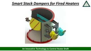
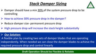
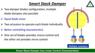
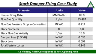
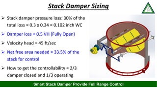
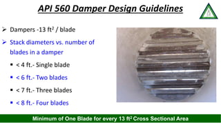
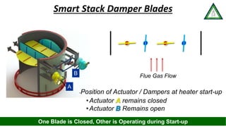
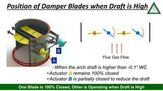
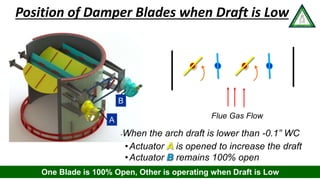
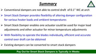
www.heatflux.com
Smart Stack Dampers for Fired Heaters
An Innovative Technology to Control Heater Draft
www.heatflux.com
 Major sections- Radiant , Convection & Stack
 Burn fuel gas with combustion air to generate heat
 Heat is transferred to the process in radiant and
convection section
 Flue gases are vented to the atmosphere safely
through stack
Fired Heaters
Fired Heaters are Major Consumers of Energy in the Petroleum Refineries
Radiant
Convection
Stack
Damper
www.heatflux.com
 Strive for perfect combustion
 Fuel side control: flowmeters, densitometers etc.
 Combustion air flow is dependent on:
 Burner air registers opening
 Stack damper opening
 Both are manually operated
 Air side control is basically missing??
Efficient Combustion
Inadequate Amount of Air Leads to Inefficiency
Combustion
www.heatflux.com
Excess O2 and Draft
 Excess air is measured by excess oxygen
 Oxygen Measurement: Major developments in the last 50 years
 Draft i.e. the negative pressure inside the heater
 Draft is maintained about 3-4 times the recommended value
 High draft causes considerable loss of energy
 Dampers are used to control the draft generated by the stack
Damper is the Final Control Element in the Fired Heater
www.heatflux.com
Dampers
 Why talk about dampers?
 Very little attention has been paid to
draft control
 Manually operated dampers
 Poor design and quality of stack damper
 Very few dampers operate properly in
the Industry
 Mostly dampers are left fully open
Damper is Very Insignificant but Important Component of the Fired Heater
www.heatflux.com
Fired Heater Draft Profile
 Flue gas pressure drop:
 Convection Section (Pb)
 Stack entry loss
 Damper loss
 Stack friction loss
 Stack exit loss
 Damper loss
 1.5 velocity heads (used in design calc)
 0.5 velocity head (fully open)
Pc
(SE)a STACK
EFFECT
IN STACK
(SE)c
NEGATIVE PRESSURE
0.05"- 0.1" W.G. AT
TOP OF RADIANT
SECTION
Pb
(SE)r
Pa
NEGATIVE
PRESSURE
POSITIVE
PRESSURE
0
STACK
EXIT LOSS
Pc
Fired Heaters has Negative Pressure Inside : Safe Equipment
www.heatflux.com
 Flue gas temperature is typically constant through out
the operation (may change by 50-100 °F at the most)
 Flue gas draft is dependent on ambient temperature
 Ambient temperature fluctuates 20-30 °F every day
 Flue gas pressure drop is proportional to (Firing Rate)2
 Excess draft available has to be used in the damper
CONVECTION
SECTION
STACK
________
BURNERS
0.05"- 0.1"
W.G. DRAFT
DRAFT AT RADIANT
SECTION OUTLET,
R0
RADIANTSECTION
Stack Design
Higher the Stack Temperature More is the Draft Available
www.heatflux.com
Available Pressure Drop Across Damper
0.00
0.20
0.40
0.60
0.80
1.00
1.20
30 46 62 78 94 110
PressureDrop,inchesWC
Heater Load, %
Draft Losses & Stack Effect Vs Heater Load
Stack Effect at 105F
Stack Effect at 60F
Stack Effect at 30F
Flue Gas Pressure Drop
Damper must consume more pressure drop
Heater Draft Availability Increases at Low Ambient Air Temp. & Reduced Load
Damper Must Consume More Pressure Drop
www.heatflux.com
 Designers provide ample margin( 10-20%) in
specifying fired heater heat duty
 API 560 standard specifies 120% overdesign on
the stack
 Stacks are designed for maximum summer
ambient temperatures 95-105°F
 Stack dia. and height are often decided by
structural stability & min. height considerations
Stacks and Dampers are Oversized
Consideration of Safety Margin is Always Good
www.heatflux.com
Conventional Stack Dampers
 Parallel or Opposed blade
operation
 All the blades are operated with a
single actuator
 All the damper blades move at the
same angle
 Non-Linear damper flow
characteristics
 10-15% area provided as clearance
around the blades
Parallel Blade
Dampers
Opposed Blade
Dampers
Conventional Dampers are not Good Enough to Provide Full Range Control
www.heatflux.com
 Needs to be adjusted continuously
 Dampers have non linear characteristics
 First 50% of damper opening controls 85%
of fluid flow
 System sensitivity changes throughout the
operating range
 Higher sensitivity - difficult damper
operation - poor draft control
HIGH
SENSIVITY
LOW
SENSIVITY
OVERSIZED
DAMPER
CURVE
LINEAR
(IDEAL)
CURVE
% DAMPER OPENING
%FULLFLOW
100
0
0
100
TYPICAL
Stack Dampers Controls
Draft Control Needs to be Continuous in Real Time
www.heatflux.com
 Damper should have a min 30% of the system pressure drop to be
controlling
 How to achieve 30% pressure drop in the damper?
 Reduce damper size- permanent pressure drop
 High pressure drop will increase the stack height substantially
 Our Solution:
A flexible plan by creating two sets of damper blades that are operating
independently. When needed we can close the damper blades to achieve the
required pressure drop and control linearly
Stack Damper Sizing
Draft Operation Should be Flexible & Reliable
www.heatflux.com
Smart Stack Damper
 Two damper blades configuration, multiple
blade dampers also possible
 Equal blade areas
 Two actuators to operate each blade individually
 Better controlling characteristics
 One set of blades provides macro control and
the other set provides micro control
Multiple Actuators
Smart Stack Damper has Linear Control Characteristics
www.heatflux.com
Stack Damper Sizing Case Study
Parameter Units Value
Heater Firing Rate MMBtu/hr 88.0
Flue Gas Quantity lb/hr 85,467
Flue Gas Pressure Drop in Convection IN WC 0.214
Stack Diameter ft 8.0
Stack Flue Gas Velocity ft/sec 15.0
Damper Loss (1.5 VH) In WC 0.036
Stack Loss In WC 0.092
Total System Losses In WC 0.342
1.5 Velocity Head Corresponds to 40% Opening Area
www.heatflux.com
 Stack damper pressure loss: 30% of the
total loss = 0.3 x 0.34 = 0.102 inch WC
 Damper loss = 0.5 VH (Fully Open)
 Velocity head = 45 ft/sec
 Net free area needed = 33.5% of the
stack for control
 How to get the controllability = 2/3
damper closed and 1/3 operating
Stack Damper Sizing
Smart Stack Damper Provide Full Range Control
www.heatflux.com
 Dampers -13 ft2 / blade
 Stack diameters vs. number of
blades in a damper
 < 4 ft.- Single blade
 < 6 ft.- Two blades
 < 7 ft.- Three blades
 < 8 ft.- Four blades
API 560 Damper Design Guidelines
Minimum of One Blade for every 13 ft2 Cross Sectional Area
www.heatflux.com
Flue Gas Flow
A
•Actuator remains closed
•Actuator Remains open
-Position of Actuator / Dampers at heater start-up
B
Smart Stack Damper Blades
One Blade is Closed, Other is Operating during Start-up
www.heatflux.com
•Actuator remains 100% closed
•Actuator is partially closed to reduce the draft
-When the arch draft is higher than -0.1” WC
Flue Gas Flow
A
B
Position of Damper Blades when Draft is High
One Blade is 100% Closed, Other is Operating when Draft is High
www.heatflux.com
Flue Gas Flow
•Actuator is opened to increase the draft
•Actuator remains 100% open
-When the arch draft is lower than -0.1” WC
Position of Damper Blades when Draft is Low
A
B
One Blade is 100% Open, Other is operating when Draft is Low
www.heatflux.com
Summary
 Conventional dampers are not able to control draft of 0.1” WC at arch
 Smart Stack Damper provides flexibility of altering damper configuration
for various heater loads and ambient temperatures
 Smart Stack Damper enables one actuator could be used for major load
adjustments and other actuator for minor temperature adjustments
 With flexibility to operate the blades individually, efficient and accurate
control over draft can be obtained
 Existing dampers can be converted to smart stack dampers
Pay Out for Smart Stack Dampers is Typically in Weeks
www.heatflux.com
Thank You!

Furnace Improvement (FIS): Smart Stack Damper

  • 2.
    www.heatflux.com Smart Stack Dampersfor Fired Heaters An Innovative Technology to Control Heater Draft
  • 3.
    www.heatflux.com  Major sections-Radiant , Convection & Stack  Burn fuel gas with combustion air to generate heat  Heat is transferred to the process in radiant and convection section  Flue gases are vented to the atmosphere safely through stack Fired Heaters Fired Heaters are Major Consumers of Energy in the Petroleum Refineries Radiant Convection Stack Damper
  • 4.
    www.heatflux.com  Strive forperfect combustion  Fuel side control: flowmeters, densitometers etc.  Combustion air flow is dependent on:  Burner air registers opening  Stack damper opening  Both are manually operated  Air side control is basically missing?? Efficient Combustion Inadequate Amount of Air Leads to Inefficiency Combustion
  • 5.
    www.heatflux.com Excess O2 andDraft  Excess air is measured by excess oxygen  Oxygen Measurement: Major developments in the last 50 years  Draft i.e. the negative pressure inside the heater  Draft is maintained about 3-4 times the recommended value  High draft causes considerable loss of energy  Dampers are used to control the draft generated by the stack Damper is the Final Control Element in the Fired Heater
  • 6.
    www.heatflux.com Dampers  Why talkabout dampers?  Very little attention has been paid to draft control  Manually operated dampers  Poor design and quality of stack damper  Very few dampers operate properly in the Industry  Mostly dampers are left fully open Damper is Very Insignificant but Important Component of the Fired Heater
  • 7.
    www.heatflux.com Fired Heater DraftProfile  Flue gas pressure drop:  Convection Section (Pb)  Stack entry loss  Damper loss  Stack friction loss  Stack exit loss  Damper loss  1.5 velocity heads (used in design calc)  0.5 velocity head (fully open) Pc (SE)a STACK EFFECT IN STACK (SE)c NEGATIVE PRESSURE 0.05"- 0.1" W.G. AT TOP OF RADIANT SECTION Pb (SE)r Pa NEGATIVE PRESSURE POSITIVE PRESSURE 0 STACK EXIT LOSS Pc Fired Heaters has Negative Pressure Inside : Safe Equipment
  • 8.
    www.heatflux.com  Flue gastemperature is typically constant through out the operation (may change by 50-100 °F at the most)  Flue gas draft is dependent on ambient temperature  Ambient temperature fluctuates 20-30 °F every day  Flue gas pressure drop is proportional to (Firing Rate)2  Excess draft available has to be used in the damper CONVECTION SECTION STACK ________ BURNERS 0.05"- 0.1" W.G. DRAFT DRAFT AT RADIANT SECTION OUTLET, R0 RADIANTSECTION Stack Design Higher the Stack Temperature More is the Draft Available
  • 9.
    www.heatflux.com Available Pressure DropAcross Damper 0.00 0.20 0.40 0.60 0.80 1.00 1.20 30 46 62 78 94 110 PressureDrop,inchesWC Heater Load, % Draft Losses & Stack Effect Vs Heater Load Stack Effect at 105F Stack Effect at 60F Stack Effect at 30F Flue Gas Pressure Drop Damper must consume more pressure drop Heater Draft Availability Increases at Low Ambient Air Temp. & Reduced Load Damper Must Consume More Pressure Drop
  • 10.
    www.heatflux.com  Designers provideample margin( 10-20%) in specifying fired heater heat duty  API 560 standard specifies 120% overdesign on the stack  Stacks are designed for maximum summer ambient temperatures 95-105°F  Stack dia. and height are often decided by structural stability & min. height considerations Stacks and Dampers are Oversized Consideration of Safety Margin is Always Good
  • 11.
    www.heatflux.com Conventional Stack Dampers Parallel or Opposed blade operation  All the blades are operated with a single actuator  All the damper blades move at the same angle  Non-Linear damper flow characteristics  10-15% area provided as clearance around the blades Parallel Blade Dampers Opposed Blade Dampers Conventional Dampers are not Good Enough to Provide Full Range Control
  • 12.
    www.heatflux.com  Needs tobe adjusted continuously  Dampers have non linear characteristics  First 50% of damper opening controls 85% of fluid flow  System sensitivity changes throughout the operating range  Higher sensitivity - difficult damper operation - poor draft control HIGH SENSIVITY LOW SENSIVITY OVERSIZED DAMPER CURVE LINEAR (IDEAL) CURVE % DAMPER OPENING %FULLFLOW 100 0 0 100 TYPICAL Stack Dampers Controls Draft Control Needs to be Continuous in Real Time
  • 13.
    www.heatflux.com  Damper shouldhave a min 30% of the system pressure drop to be controlling  How to achieve 30% pressure drop in the damper?  Reduce damper size- permanent pressure drop  High pressure drop will increase the stack height substantially  Our Solution: A flexible plan by creating two sets of damper blades that are operating independently. When needed we can close the damper blades to achieve the required pressure drop and control linearly Stack Damper Sizing Draft Operation Should be Flexible & Reliable
  • 14.
    www.heatflux.com Smart Stack Damper Two damper blades configuration, multiple blade dampers also possible  Equal blade areas  Two actuators to operate each blade individually  Better controlling characteristics  One set of blades provides macro control and the other set provides micro control Multiple Actuators Smart Stack Damper has Linear Control Characteristics
  • 15.
    www.heatflux.com Stack Damper SizingCase Study Parameter Units Value Heater Firing Rate MMBtu/hr 88.0 Flue Gas Quantity lb/hr 85,467 Flue Gas Pressure Drop in Convection IN WC 0.214 Stack Diameter ft 8.0 Stack Flue Gas Velocity ft/sec 15.0 Damper Loss (1.5 VH) In WC 0.036 Stack Loss In WC 0.092 Total System Losses In WC 0.342 1.5 Velocity Head Corresponds to 40% Opening Area
  • 16.
    www.heatflux.com  Stack damperpressure loss: 30% of the total loss = 0.3 x 0.34 = 0.102 inch WC  Damper loss = 0.5 VH (Fully Open)  Velocity head = 45 ft/sec  Net free area needed = 33.5% of the stack for control  How to get the controllability = 2/3 damper closed and 1/3 operating Stack Damper Sizing Smart Stack Damper Provide Full Range Control
  • 17.
    www.heatflux.com  Dampers -13ft2 / blade  Stack diameters vs. number of blades in a damper  < 4 ft.- Single blade  < 6 ft.- Two blades  < 7 ft.- Three blades  < 8 ft.- Four blades API 560 Damper Design Guidelines Minimum of One Blade for every 13 ft2 Cross Sectional Area
  • 18.
    www.heatflux.com Flue Gas Flow A •Actuatorremains closed •Actuator Remains open -Position of Actuator / Dampers at heater start-up B Smart Stack Damper Blades One Blade is Closed, Other is Operating during Start-up
  • 19.
    www.heatflux.com •Actuator remains 100%closed •Actuator is partially closed to reduce the draft -When the arch draft is higher than -0.1” WC Flue Gas Flow A B Position of Damper Blades when Draft is High One Blade is 100% Closed, Other is Operating when Draft is High
  • 20.
    www.heatflux.com Flue Gas Flow •Actuatoris opened to increase the draft •Actuator remains 100% open -When the arch draft is lower than -0.1” WC Position of Damper Blades when Draft is Low A B One Blade is 100% Open, Other is operating when Draft is Low
  • 21.
    www.heatflux.com Summary  Conventional dampersare not able to control draft of 0.1” WC at arch  Smart Stack Damper provides flexibility of altering damper configuration for various heater loads and ambient temperatures  Smart Stack Damper enables one actuator could be used for major load adjustments and other actuator for minor temperature adjustments  With flexibility to operate the blades individually, efficient and accurate control over draft can be obtained  Existing dampers can be converted to smart stack dampers Pay Out for Smart Stack Dampers is Typically in Weeks
  • 22.

Editor's Notes

  • #3 Smart Stack damper is an innovative technology to control heater draft
  • #4 Fired Heaters consists of radiant, convection and stack. Combustion takes place in the firebox, heat generated is transferred to the process fluid in the radiant and convection section and the flue gases are vented to the atmosphere through the stack.
  • #5 Combustion is basically reaction of fuel gas and air. If we talk about the efficiency of combustion, it depends on the proper amount of air available for combustion. In fuel gas side we do have instruments for measuring the flowrate, density and variations. We are spending million of dollars in upgrading the instruments to achieve reliability. but the combustion air is controlled manually
  • #6 Though we have dampers to control the heater draft but as it is manually operated by the operators, mostly it is left fully open. Due to this the heater has more negative draft at the arch level. It leads to the tramp air leakage into the heater which reduces the efficiency by 1 or 2%.
  • #7 Even though the damper is very insignificant component of the heater but it plays a very important role. Most of the times its operation is overlooked by the operators. Very few dampers operate properly in the industry.
  • #8 Fired Heaters are inherently safe equipment and that is where we have negative pressure inside the fired heaters. Flue gases flowing through heaters encounter pressure drops which need to be provided by the stack height.
  • #9 Stacks provide draft due to density difference. If the stack temperature goes up or the ambient temperature goes down the density difference increases which increases the draft availability
  • #11 When we are designing fired heaters, we tend try to overdesign everything including stacks. Safety margin is considered good . Large stack diameter and height ensures overfiring of the heaters. Our smart damper provides variable resistance to provide you with  flexibility.
  • #12 There are two types of dampers : Parallel Blade Opposed Blade Opposed blade dampers have better control characteristics but still not good enough to provide full range control.
  • #13 Draft control needs to be continuous in real time. Current situation of stack dampers is very poor. Most of them are manually operated. Draft indication is generally local. Plant operators give up on stack dampers as they find the stack dampers cannot control stack draft effectively.
  • #15 Change the control characteristics of damper, It Introduce Resistance Reliability- Very high, properly engineered, Operator friendly, Avoid tramp air leakage, Can be controlled from the control room