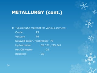
FIRED HEATER
DESIGN
1
PROCESS
CONSIDERATIONS:
Maintain hydraulic symmetry:-Pipe lengths,
fittings shall be same for all passes.
Vaporizing Fluids Min.no. of passes.
Min. radiation loss ( based on LHV):
Without APH=1.5% With APH=2.5%
Arch pressure:
Normal Value -2.5 MMWG
2
PROCESS CONSIDERATIONS
(cont.)
 Min. excess air:
(A) Natural Draft:-
Gas Firing 10%
Oil Firing 15%
(B) Forced Draft:-
Gas Firing 5%
Oil Firing 10%
3
RADIANT SECTION DESIGN
 Radiant average flux ( Kcal/Hr/M2 ):
Crude 32500
Vacuum / Naphtha / DHDS 27100
Delayed coker / Visbreaker 25000
 Maximum film temp shall not be exceeded.
 Maximum metal temp shall not be exceeded.
 Max. volumetric heat release:
Oil Firing 107 Kcal/M3
Gas Firing 142 Kcal/M3
4
RADIANT SECTION DESIGN
(cont.)
 Vertical cylindrical heaters:
H / D < 2.75
 Horizontal tube heaters:
H / W < 2.75
 Max. length for Vertical tubes = 18.3 M
 Max. unsupported length for Horizontal tubes = lesser of 35
OD or 6M
 Min. distance b/w refractory & tube center = 1.5Xnominal
diameter
 Duty absorbed in radiant = 60-70% of total absorbed duty
 Normal Bridge wall temp = 600 - 800 deg C
 Min design temp for tube support = 871 deg C
5
CONVECTION SECTION
DESIGN
 Flue gas mass velocity ( Kg/S/M2):
Natural draft : 1.5 - 3.0
Forced draft : 3.0 - 4.5
 Process mass velocity = 1220 - 1710 Kg/S/M2
 Typical flue gas side heat transfer coefficient is between
15 - 25 Kcal/Hr/M2/K.
 Types of extended surfaces:
Studs : for heavy fuels ( viz. Fuel oil )
Fins : for lighter fuels ( viz. Fuel gas, Bio gas)
6
CONVECTION SECTION DESIGN
(cont.)
 Normally first 3 rows are considered as shield tubes.
Hence no extended surfaces are provided to prevent
overheating of these tubes.
 Never exceed critical velocity.
 Maximum film temp shall not be exceeded.
 Maximum metal (tube & extended surfaces) temp shall
not be exceeded.
7
STACK DESIGN
 Stack is designed to maintain -2.5 MMWG pressure at
minimum 120% of design heat release with design excess
air & max. ambient temp.
 Draft Analysis:
Draft = 0.1203 * Pa * ( ( Mwa / Ta ) - ( MWf / Tf ) ) * ( Z2-
Z1 )
Where,
Pa = Ambient air pressure @ grade level (KPa)
Ta, Tf = Ambient air & Flue gas temp respectively ( K)
Mwa , MWf = Mol. Wt. of air & flue gas respectively ( Kg/Kg
mol )
Z2, Z1 = Elevation of point 1 & 2 respectively (M)
8
STACK DESIGN (cont.)
 Total draft Gain = draft gain in convection + draft gain in
stack.
 Total pressure loss = pressure loss in convection ( entry
loss, loss across tubes & exit loss ) +
pressure loss in stack ( entry loss,damper
loss, friction loss & exit loss )
 For viable design,
Arch pressure - Total pressure loss = Total draft gain
 Normal Flue gas velocity in stack:
Natural draft 8 M / S
Induced draft 15 - 20 M / S
9
STACK DESIGN (cont.)
 Flue gas condensation:
Sulfur dioxide produced as a result of combustion converts
into SO3 and reacts with water vapor present in the flue gas
to form sulfuric acid. This sulfuric acid at low temperature
condenses on the inside surface of the refractory. This is
harmful for both the refractory & the casing.
Flue gas dew point depends on:
(A) Fuel sulfur content
(B) Flue gas O2 content
(C) Flue gas moisture content
(D) Combustion temp
(E) Fuel & flue gas additives
To avoid flue gas condensation, the flue gas temp is kept min
20-30 deg C above the flue gas dew point.
10
FORCED DRAFT FAN
 FD fans are designed with min 15 % margin over air flow rate
corresponding to design heat release.
 FD fan discharge pressure should be capable enough to over
come:
(A)Combustion air duct pressure loss ( straight & fittings )
(B)APH
(C)Burners
 Design velocities in combustion air duct:
Straight, Tee, Turns ~15 M / S
Burner air supply & Plenum duct 7.5 - 10.5 M / S
 Normally Centrifugal fan with fixed speed drive are used.
Capacity control is done by either Inlet guide vans / Inlet /
Outlet damper.
11
FORCED DRAFT FAN (cont.)
 For critical applications ( viz. CDU/VDU etc.) 2 FD fans
are provided.
 Two options are used in case of 2 FD fans provided:
(A) 1 fan is running, other is standby - simple & cheaper
but less reliable.
(B) Both the fans are running at 50 % load - costly but
more reliable.
 MOC of casing - CS
MOC of Impeller - CS
12
FORCED DRAFT FAN (cont.)
 Following parameters to be specified for the selection of
FD fan:
(A) Flow rate: Min / Nor / Max
(B) Temp: Min / Nor / Max / Design
(C) Inlet Pressure: Min / Nor
(D) Outlet Pressure : Nor / Max
(E) Air composition
(F) Driver : Motor / Steam turbine
(G) Spares
13
INDUCED DRAFT FAN
 ID fans are designed with min 20 % margin over flue
gas flow rate corresponding to design heat release.
 Normal discharge pressure of ID fan is ambient
pressure.
 Suction pressure = arch pressure - total pressure loss in
convection -
total pressure loss in off take duct- pressure
drop in inlet damper.
 Design velocities in off take duct:
Straight, Tee, Turns ~12 M / S
 MOC of casing - CS / SS
MOC of Impeller - CS / SS / Corten Steel A
14
INDUCED DRAFT FAN (cont.)
 Types of drive:
( A) Fixed speed drive (1000 or 1500 rpm ) - Capacity
control by Inlet guide vans/ Inlet damper
(B) Variable speed drive ( Fluid coupling, VFD ) -
Capacity control by varying speed.
Q  n , H  n2 , P  n3
 Care must be taken to avoid flue gas condensation on
the Impeller. Hence the minimum temperature at ID fan
inlet shall be about 25-30 deg C above dew point.
15
INDUCED DRAFT FAN (cont.)
 Following parameters to be specified for the selection of
ID fan:
(A) Flow rate: Min / Nor / Max
(B) Temp: Min / Nor / Max / Design
(C) Inlet Pressure: Min / Nor
(D) Outlet Pressure : Nor / Max
(E) Flue gas composition
(F) Driver : Motor / Steam turbine
(G) Spares
16
BURNERS
 Types of Burners:
(A) Gas Firing
(B) Oil Firing
(C) Combination Firing
 No. of burners required for a given heat release shall be
optimized based on following criteria:
(A) In normal cases, max heat release per burner shall not
exceed 3.0 MMKCal/Hr.
(B) Turndown requirements
(C) Flame dimension: ( Flame impingement on tubes,
refractory & adjacent burners shall be avoided )
(D) Heat distribution requirements
17
BURNERS (cont.)
 Component of Burner:
Main Gas/Oil tips , Pilot tip , Main flame scanner ( IR / UV ) ,
Pilot flame scanner ( Ionization rod ) , Igniter , Sight ports.
 No. of Burners Max./Nor. Heat Release
<5 1.25
6-7 1.20
>8 1.15
 Min Pilot heat release 20000 Kcal/Hr
 Type of Oil atomization:
(A) Pressure atomization = min oil pr. ~ 10 Kg/Cm2g
(B) Steam atomization = steam/oil ~ 0.3 Kg/Kg & Delta P
~2.1 Kg/Cm2
 For Oil fired burners, max. viscosity is 43 CSt.
18
BURNERS (cont.)
 Generation of pollutants from Burner:
(A) SOx : Sox (SO2 & SO3 ) generation chiefly depends on
the sulfur content of the fuel.
(B) NOx : NOx (NO & NO2 ) is generated thermally by the
reaction occurring above 700-800 deg C. Methods of NOx
reduction are:
Splitting fuel within burner
Splitting combustion air within burner
Diluting air-fuel mixture by flue gas mixing.
Normal limit is 50-125 ppmv for gas firing & 200-250 ppmv
for oil firing.
(C) Unburnt hydrocarbon: Result of improper mixing of fuel
with air.
(D) SPM: Soot, ash etc. Refraction method is used to monitor
the SPM content in flue gas.
19
BURNERS (cont.)
 Min parameters required for burner selection:
(A) Heat release : Min / Nor / Max
(B) Type of burner : Natural draft, Forced Draft, Low
Nox, Combination.
(C) Fuel details : Composition, LHV, Pressure,
Temperature
(D) Combustion air details: Temperature, Pressure,
Relative humidity
(E) Nos. of burners, Ignition details.
(F) Emission requirements: SOx, NOx, UHC, SPM, CO
etc.
(G) Noise limitation: 85 dBA A 1M from burner.
20
AIR PREHEATER
 Advantages of APH :
(A) Enhance efficiency ( up 92-93 %).
(B) To enhance air-fuel mixing ( High air velocity ).
(C) Reduce oil burner fouling
(D) More complete combustion of difficult fuels.
 Disadvantages of APH:
(A) Increases potential of SO3 & NOx generation as
adiabatic flame temperature is high.
(B) Reduces the stack temp., so either ID fan or taller
stack will be required.
21
AIR PREHEATER (cont.)
 Steam air preheater (SAPH) is used when ambient air temp.
falls to a very low value.
 Type of Air preheaters (recuperative type ) normally used in
refinery services:
(A) Tube Type: Tubes made of cast iron or glass. When cast
iron tubes are provided, the min. metal temp is kept 10-15
deg above dew point.
Adv: Very low leakage, Easy to design & fabricate, normally
Low unit cost, easy for maintainence.
Disadv: Higher pressure drop as compared to plate type,
Heavy so increases the structural cost if placed onboard,
glass tubes may damage during transportation..
22
AIR PREHEATER (cont.)
(B) Plate Type: Typically it contains carbon steel
plates(typically 2mm thick) assembled in a frame. These
modules are standard in size and required capacity is
obtained by increasing the number of modules.
Adv: Low pressure drop, Light in weight & compact, so
mostly used as onboard unit.
Disadv: Costly maintenance, easy to foul &
corrode(sometimes porcelain enameled plates are used
), high unit cost.
23
AIR PREHEATERS (cont.)
 Min data required for air preheater specification:
(A) Air / Flue gas flowrates : Min / Nor / Max
(B) Air / Flue gas temperatures (in/out): Min / Nor / Max
/ Des
(C) Air / Flue gas pressures (in) : Min / Nor / Max / Des
(D) Type of APH
(E) Duty : Nor/ Max
(F) Allowable pressure drop ( Air side / Flue gas side )
(G) Sulfur dew point of flue gas
(H) Flue gas composition
(I) Requirements of tube skin thermocouple.
24
SOOTBLOWERS
 Soot is generated as a result of improper combustion in
burners.
 Soot has to be removed to maintain heat transfer
coefficient.
 Type of soot blowers:
(A) Retractable type: Mostly use for high temperature
& dirtier fuel application. It is more costly but has better
cleaning characteristics.
Normally it is used in fully automatic sequential mode.
(B) Fixed Rotary type: It is cheaper than Retractable
type but can not be used in high temperature or dirty
fuel services.
(C) Vibration type: Ultrasound waves are used in this
type to create vibration to disengage the soot from the
coils. Very limited experience is available for this type.
25
SOOT BLOWERS (cont.)
 Min steam flowrate required : 4535 Kg/Hr
 Min steam pressure required : 10 Kg/Cm2 g
 Each soot blower should cover maximum 1.2M or 5
rows, whichever is less.
 Some times steam lancing nozzles are provided to
remove soot for smaller installations.
26
DAMPERS
 Type of Dampers:
(A) Control damper: It controls the draft in the heater.
It can be either manual or automatic in operation. It
always has some leakage ( ~3%). It can be single blade
( like butterfly damper ) or multiple blade ( like louver
damper ). Multiple blade damper can have parallel blade
opening or opposed blade opening ( better control but
complex in operation).
No. of Blades ~ inside area of the duct or stack (M2) /
1.2
Control damper is normally use in stack, FD/ID fan and
combustion air bypass around the APH.
27
DAMPERS (cont.)
(B) Shut off damper:It is used to prevent the flow
through a duct. It can be operable manually by chain &
pulley arrangement ( as in Guillotine blind ) or by an
electric motor ( as in swing gate ). It is designed for a
very high sealing efficiency ( 99.9%).
(C) Diverter damper: It is used to divert the flow of air or
flue gas from one duct to another duct.
28
INSTRUMENTATIONS
 Applicable code is OISD 111.
 Following instruments are normally provided:
Draft gauge for radiant, convection, stack.
High / low arch pressure ( trip / alarm ).
High arch temperature ( alarm ).
Oxygen / CO analyzer in arch ( Alarm ).
Convection outlet temperature / pressure.
Stack outlet temperature / pressure.
SPM / NOx / SOx analyzers.
29
INSTRUMENTATIONS (cont.)
Nozzles for pollution monitoring.
Tube skin temperatures in coil / APH.
Process fluid inlet & outlet temperature / pressure.
30
REFRACTORIES
 Type of refractories:
(A) High Density Fire Bricks(HDFB): These are normally
placed on the floor to protect the mechanically weak castables
/ bricks. They have excellent mechanical strength but very
poor thermal insulation properties.They are laid loose on the
floor. Exp. AC30 etc.
(B) Insulating Fire Bricks(IFB): These are normally placed
on radiant floor (below HDFB), radiant wall and sometimes in
vertical flue gas ducts. They are lighter than HDFB and hence
mechanically poor. Application of IFB requires more time than
castables / ceramic fibres. They are laid with mortar and
expansion gaps are provided to accommodate the thermal
expansion of the bricks. Exp. JM 23, JM 26 etc.
31
REFRACTORIES (cont.)
(C) Castables: Castable are placed in all parts of fired
heater. They can be mechanically very strong ( as
Insulyte 15Li ) or thermally very superior ( like Firelite
124). They are applied on the surface by pouring or
gunning. Anchors (CS or SS-304, depending on the tip
temperature) are used to hold the castable with the
casing. Normally V, Y or chain link type anchors are
used.
Castable can be applied in dual layer also. In dual layer
construction, a mechanically superior castable is used on
hot face & thermally superior castable on cold surface.
Sometimes ceramic blocks are used in place of
castables. Exp. Cerablok-800 etc.
32
REFRACTORIES (cont.)
(D) Ceramic Fibres: These refractory materials are
very light weight, thermally superior but mechanically
poor material. They are used as loose fibres for filling
gaps, blankets or module for application on casing
plates. They can not be used where the flue gas velocity
is 40fps ( for blankets) or 80fps( for modules). Further,
they can not be applied where the total metal content
exceeds 100 ppm. They are fixed to the casing by studs
& nuts. Application is very fast. Due to their low weight,
they can potentially reduce the structural cost. Normally
a vapour barrier (0.1 mm SS-304 foil) and an
anticorrosive paint are used to avert the flue gas
condensation on the casing plate. Exp: Cerablanket
1260, Cerablanket 1450 etc.
33
METALLURGY
 Process affects the material selection:
(A) Oxidation at high temperature.
(B) Vanadium & sodium attack in presence of sulfur.
(C) Attack by H2S.
(D) Attack by Polythionic acid.
(E) Attack by Chlorine.
(F) Attack by H2.
(G) Carburisation.
34
METALLURGY (cont.)
 Following tube materials are normally used:
Carbon Steel - 525 deg C
Low alloy steel (P11,P22) - 525 deg C
High alloy steel ( P5, P9) -600 deg C
Austenitic Stainless Steel
( SS304 / 310 / 321 / 347) -820 deg C
 Following support materials are normally used:
CS : 427oC, 25Cr-20Ni : 871oC, 50Cr-50Ni-Cb : 982oC
 Heater casing is always made of carbon steel.
35
METALLURGY (cont.)
 Typical tube material for various services:
Crude P5
Vacuum P9
Delayed coker / Visbreaker P9
Hydrotreater SS 321 / SS 347
Hot Oil Heater CS
Reboilers CS
36

fired heater design , fired heater design

  • 1.
  • 2.
    PROCESS CONSIDERATIONS: Maintain hydraulic symmetry:-Pipelengths, fittings shall be same for all passes. Vaporizing Fluids Min.no. of passes. Min. radiation loss ( based on LHV): Without APH=1.5% With APH=2.5% Arch pressure: Normal Value -2.5 MMWG 2
  • 3.
    PROCESS CONSIDERATIONS (cont.)  Min.excess air: (A) Natural Draft:- Gas Firing 10% Oil Firing 15% (B) Forced Draft:- Gas Firing 5% Oil Firing 10% 3
  • 4.
    RADIANT SECTION DESIGN Radiant average flux ( Kcal/Hr/M2 ): Crude 32500 Vacuum / Naphtha / DHDS 27100 Delayed coker / Visbreaker 25000  Maximum film temp shall not be exceeded.  Maximum metal temp shall not be exceeded.  Max. volumetric heat release: Oil Firing 107 Kcal/M3 Gas Firing 142 Kcal/M3 4
  • 5.
    RADIANT SECTION DESIGN (cont.) Vertical cylindrical heaters: H / D < 2.75  Horizontal tube heaters: H / W < 2.75  Max. length for Vertical tubes = 18.3 M  Max. unsupported length for Horizontal tubes = lesser of 35 OD or 6M  Min. distance b/w refractory & tube center = 1.5Xnominal diameter  Duty absorbed in radiant = 60-70% of total absorbed duty  Normal Bridge wall temp = 600 - 800 deg C  Min design temp for tube support = 871 deg C 5
  • 6.
    CONVECTION SECTION DESIGN  Fluegas mass velocity ( Kg/S/M2): Natural draft : 1.5 - 3.0 Forced draft : 3.0 - 4.5  Process mass velocity = 1220 - 1710 Kg/S/M2  Typical flue gas side heat transfer coefficient is between 15 - 25 Kcal/Hr/M2/K.  Types of extended surfaces: Studs : for heavy fuels ( viz. Fuel oil ) Fins : for lighter fuels ( viz. Fuel gas, Bio gas) 6
  • 7.
    CONVECTION SECTION DESIGN (cont.) Normally first 3 rows are considered as shield tubes. Hence no extended surfaces are provided to prevent overheating of these tubes.  Never exceed critical velocity.  Maximum film temp shall not be exceeded.  Maximum metal (tube & extended surfaces) temp shall not be exceeded. 7
  • 8.
    STACK DESIGN  Stackis designed to maintain -2.5 MMWG pressure at minimum 120% of design heat release with design excess air & max. ambient temp.  Draft Analysis: Draft = 0.1203 * Pa * ( ( Mwa / Ta ) - ( MWf / Tf ) ) * ( Z2- Z1 ) Where, Pa = Ambient air pressure @ grade level (KPa) Ta, Tf = Ambient air & Flue gas temp respectively ( K) Mwa , MWf = Mol. Wt. of air & flue gas respectively ( Kg/Kg mol ) Z2, Z1 = Elevation of point 1 & 2 respectively (M) 8
  • 9.
    STACK DESIGN (cont.) Total draft Gain = draft gain in convection + draft gain in stack.  Total pressure loss = pressure loss in convection ( entry loss, loss across tubes & exit loss ) + pressure loss in stack ( entry loss,damper loss, friction loss & exit loss )  For viable design, Arch pressure - Total pressure loss = Total draft gain  Normal Flue gas velocity in stack: Natural draft 8 M / S Induced draft 15 - 20 M / S 9
  • 10.
    STACK DESIGN (cont.) Flue gas condensation: Sulfur dioxide produced as a result of combustion converts into SO3 and reacts with water vapor present in the flue gas to form sulfuric acid. This sulfuric acid at low temperature condenses on the inside surface of the refractory. This is harmful for both the refractory & the casing. Flue gas dew point depends on: (A) Fuel sulfur content (B) Flue gas O2 content (C) Flue gas moisture content (D) Combustion temp (E) Fuel & flue gas additives To avoid flue gas condensation, the flue gas temp is kept min 20-30 deg C above the flue gas dew point. 10
  • 11.
    FORCED DRAFT FAN FD fans are designed with min 15 % margin over air flow rate corresponding to design heat release.  FD fan discharge pressure should be capable enough to over come: (A)Combustion air duct pressure loss ( straight & fittings ) (B)APH (C)Burners  Design velocities in combustion air duct: Straight, Tee, Turns ~15 M / S Burner air supply & Plenum duct 7.5 - 10.5 M / S  Normally Centrifugal fan with fixed speed drive are used. Capacity control is done by either Inlet guide vans / Inlet / Outlet damper. 11
  • 12.
    FORCED DRAFT FAN(cont.)  For critical applications ( viz. CDU/VDU etc.) 2 FD fans are provided.  Two options are used in case of 2 FD fans provided: (A) 1 fan is running, other is standby - simple & cheaper but less reliable. (B) Both the fans are running at 50 % load - costly but more reliable.  MOC of casing - CS MOC of Impeller - CS 12
  • 13.
    FORCED DRAFT FAN(cont.)  Following parameters to be specified for the selection of FD fan: (A) Flow rate: Min / Nor / Max (B) Temp: Min / Nor / Max / Design (C) Inlet Pressure: Min / Nor (D) Outlet Pressure : Nor / Max (E) Air composition (F) Driver : Motor / Steam turbine (G) Spares 13
  • 14.
    INDUCED DRAFT FAN ID fans are designed with min 20 % margin over flue gas flow rate corresponding to design heat release.  Normal discharge pressure of ID fan is ambient pressure.  Suction pressure = arch pressure - total pressure loss in convection - total pressure loss in off take duct- pressure drop in inlet damper.  Design velocities in off take duct: Straight, Tee, Turns ~12 M / S  MOC of casing - CS / SS MOC of Impeller - CS / SS / Corten Steel A 14
  • 15.
    INDUCED DRAFT FAN(cont.)  Types of drive: ( A) Fixed speed drive (1000 or 1500 rpm ) - Capacity control by Inlet guide vans/ Inlet damper (B) Variable speed drive ( Fluid coupling, VFD ) - Capacity control by varying speed. Q  n , H  n2 , P  n3  Care must be taken to avoid flue gas condensation on the Impeller. Hence the minimum temperature at ID fan inlet shall be about 25-30 deg C above dew point. 15
  • 16.
    INDUCED DRAFT FAN(cont.)  Following parameters to be specified for the selection of ID fan: (A) Flow rate: Min / Nor / Max (B) Temp: Min / Nor / Max / Design (C) Inlet Pressure: Min / Nor (D) Outlet Pressure : Nor / Max (E) Flue gas composition (F) Driver : Motor / Steam turbine (G) Spares 16
  • 17.
    BURNERS  Types ofBurners: (A) Gas Firing (B) Oil Firing (C) Combination Firing  No. of burners required for a given heat release shall be optimized based on following criteria: (A) In normal cases, max heat release per burner shall not exceed 3.0 MMKCal/Hr. (B) Turndown requirements (C) Flame dimension: ( Flame impingement on tubes, refractory & adjacent burners shall be avoided ) (D) Heat distribution requirements 17
  • 18.
    BURNERS (cont.)  Componentof Burner: Main Gas/Oil tips , Pilot tip , Main flame scanner ( IR / UV ) , Pilot flame scanner ( Ionization rod ) , Igniter , Sight ports.  No. of Burners Max./Nor. Heat Release <5 1.25 6-7 1.20 >8 1.15  Min Pilot heat release 20000 Kcal/Hr  Type of Oil atomization: (A) Pressure atomization = min oil pr. ~ 10 Kg/Cm2g (B) Steam atomization = steam/oil ~ 0.3 Kg/Kg & Delta P ~2.1 Kg/Cm2  For Oil fired burners, max. viscosity is 43 CSt. 18
  • 19.
    BURNERS (cont.)  Generationof pollutants from Burner: (A) SOx : Sox (SO2 & SO3 ) generation chiefly depends on the sulfur content of the fuel. (B) NOx : NOx (NO & NO2 ) is generated thermally by the reaction occurring above 700-800 deg C. Methods of NOx reduction are: Splitting fuel within burner Splitting combustion air within burner Diluting air-fuel mixture by flue gas mixing. Normal limit is 50-125 ppmv for gas firing & 200-250 ppmv for oil firing. (C) Unburnt hydrocarbon: Result of improper mixing of fuel with air. (D) SPM: Soot, ash etc. Refraction method is used to monitor the SPM content in flue gas. 19
  • 20.
    BURNERS (cont.)  Minparameters required for burner selection: (A) Heat release : Min / Nor / Max (B) Type of burner : Natural draft, Forced Draft, Low Nox, Combination. (C) Fuel details : Composition, LHV, Pressure, Temperature (D) Combustion air details: Temperature, Pressure, Relative humidity (E) Nos. of burners, Ignition details. (F) Emission requirements: SOx, NOx, UHC, SPM, CO etc. (G) Noise limitation: 85 dBA A 1M from burner. 20
  • 21.
    AIR PREHEATER  Advantagesof APH : (A) Enhance efficiency ( up 92-93 %). (B) To enhance air-fuel mixing ( High air velocity ). (C) Reduce oil burner fouling (D) More complete combustion of difficult fuels.  Disadvantages of APH: (A) Increases potential of SO3 & NOx generation as adiabatic flame temperature is high. (B) Reduces the stack temp., so either ID fan or taller stack will be required. 21
  • 22.
    AIR PREHEATER (cont.) Steam air preheater (SAPH) is used when ambient air temp. falls to a very low value.  Type of Air preheaters (recuperative type ) normally used in refinery services: (A) Tube Type: Tubes made of cast iron or glass. When cast iron tubes are provided, the min. metal temp is kept 10-15 deg above dew point. Adv: Very low leakage, Easy to design & fabricate, normally Low unit cost, easy for maintainence. Disadv: Higher pressure drop as compared to plate type, Heavy so increases the structural cost if placed onboard, glass tubes may damage during transportation.. 22
  • 23.
    AIR PREHEATER (cont.) (B)Plate Type: Typically it contains carbon steel plates(typically 2mm thick) assembled in a frame. These modules are standard in size and required capacity is obtained by increasing the number of modules. Adv: Low pressure drop, Light in weight & compact, so mostly used as onboard unit. Disadv: Costly maintenance, easy to foul & corrode(sometimes porcelain enameled plates are used ), high unit cost. 23
  • 24.
    AIR PREHEATERS (cont.) Min data required for air preheater specification: (A) Air / Flue gas flowrates : Min / Nor / Max (B) Air / Flue gas temperatures (in/out): Min / Nor / Max / Des (C) Air / Flue gas pressures (in) : Min / Nor / Max / Des (D) Type of APH (E) Duty : Nor/ Max (F) Allowable pressure drop ( Air side / Flue gas side ) (G) Sulfur dew point of flue gas (H) Flue gas composition (I) Requirements of tube skin thermocouple. 24
  • 25.
    SOOTBLOWERS  Soot isgenerated as a result of improper combustion in burners.  Soot has to be removed to maintain heat transfer coefficient.  Type of soot blowers: (A) Retractable type: Mostly use for high temperature & dirtier fuel application. It is more costly but has better cleaning characteristics. Normally it is used in fully automatic sequential mode. (B) Fixed Rotary type: It is cheaper than Retractable type but can not be used in high temperature or dirty fuel services. (C) Vibration type: Ultrasound waves are used in this type to create vibration to disengage the soot from the coils. Very limited experience is available for this type. 25
  • 26.
    SOOT BLOWERS (cont.) Min steam flowrate required : 4535 Kg/Hr  Min steam pressure required : 10 Kg/Cm2 g  Each soot blower should cover maximum 1.2M or 5 rows, whichever is less.  Some times steam lancing nozzles are provided to remove soot for smaller installations. 26
  • 27.
    DAMPERS  Type ofDampers: (A) Control damper: It controls the draft in the heater. It can be either manual or automatic in operation. It always has some leakage ( ~3%). It can be single blade ( like butterfly damper ) or multiple blade ( like louver damper ). Multiple blade damper can have parallel blade opening or opposed blade opening ( better control but complex in operation). No. of Blades ~ inside area of the duct or stack (M2) / 1.2 Control damper is normally use in stack, FD/ID fan and combustion air bypass around the APH. 27
  • 28.
    DAMPERS (cont.) (B) Shutoff damper:It is used to prevent the flow through a duct. It can be operable manually by chain & pulley arrangement ( as in Guillotine blind ) or by an electric motor ( as in swing gate ). It is designed for a very high sealing efficiency ( 99.9%). (C) Diverter damper: It is used to divert the flow of air or flue gas from one duct to another duct. 28
  • 29.
    INSTRUMENTATIONS  Applicable codeis OISD 111.  Following instruments are normally provided: Draft gauge for radiant, convection, stack. High / low arch pressure ( trip / alarm ). High arch temperature ( alarm ). Oxygen / CO analyzer in arch ( Alarm ). Convection outlet temperature / pressure. Stack outlet temperature / pressure. SPM / NOx / SOx analyzers. 29
  • 30.
    INSTRUMENTATIONS (cont.) Nozzles forpollution monitoring. Tube skin temperatures in coil / APH. Process fluid inlet & outlet temperature / pressure. 30
  • 31.
    REFRACTORIES  Type ofrefractories: (A) High Density Fire Bricks(HDFB): These are normally placed on the floor to protect the mechanically weak castables / bricks. They have excellent mechanical strength but very poor thermal insulation properties.They are laid loose on the floor. Exp. AC30 etc. (B) Insulating Fire Bricks(IFB): These are normally placed on radiant floor (below HDFB), radiant wall and sometimes in vertical flue gas ducts. They are lighter than HDFB and hence mechanically poor. Application of IFB requires more time than castables / ceramic fibres. They are laid with mortar and expansion gaps are provided to accommodate the thermal expansion of the bricks. Exp. JM 23, JM 26 etc. 31
  • 32.
    REFRACTORIES (cont.) (C) Castables:Castable are placed in all parts of fired heater. They can be mechanically very strong ( as Insulyte 15Li ) or thermally very superior ( like Firelite 124). They are applied on the surface by pouring or gunning. Anchors (CS or SS-304, depending on the tip temperature) are used to hold the castable with the casing. Normally V, Y or chain link type anchors are used. Castable can be applied in dual layer also. In dual layer construction, a mechanically superior castable is used on hot face & thermally superior castable on cold surface. Sometimes ceramic blocks are used in place of castables. Exp. Cerablok-800 etc. 32
  • 33.
    REFRACTORIES (cont.) (D) CeramicFibres: These refractory materials are very light weight, thermally superior but mechanically poor material. They are used as loose fibres for filling gaps, blankets or module for application on casing plates. They can not be used where the flue gas velocity is 40fps ( for blankets) or 80fps( for modules). Further, they can not be applied where the total metal content exceeds 100 ppm. They are fixed to the casing by studs & nuts. Application is very fast. Due to their low weight, they can potentially reduce the structural cost. Normally a vapour barrier (0.1 mm SS-304 foil) and an anticorrosive paint are used to avert the flue gas condensation on the casing plate. Exp: Cerablanket 1260, Cerablanket 1450 etc. 33
  • 34.
    METALLURGY  Process affectsthe material selection: (A) Oxidation at high temperature. (B) Vanadium & sodium attack in presence of sulfur. (C) Attack by H2S. (D) Attack by Polythionic acid. (E) Attack by Chlorine. (F) Attack by H2. (G) Carburisation. 34
  • 35.
    METALLURGY (cont.)  Followingtube materials are normally used: Carbon Steel - 525 deg C Low alloy steel (P11,P22) - 525 deg C High alloy steel ( P5, P9) -600 deg C Austenitic Stainless Steel ( SS304 / 310 / 321 / 347) -820 deg C  Following support materials are normally used: CS : 427oC, 25Cr-20Ni : 871oC, 50Cr-50Ni-Cb : 982oC  Heater casing is always made of carbon steel. 35
  • 36.
    METALLURGY (cont.)  Typicaltube material for various services: Crude P5 Vacuum P9 Delayed coker / Visbreaker P9 Hydrotreater SS 321 / SS 347 Hot Oil Heater CS Reboilers CS 36