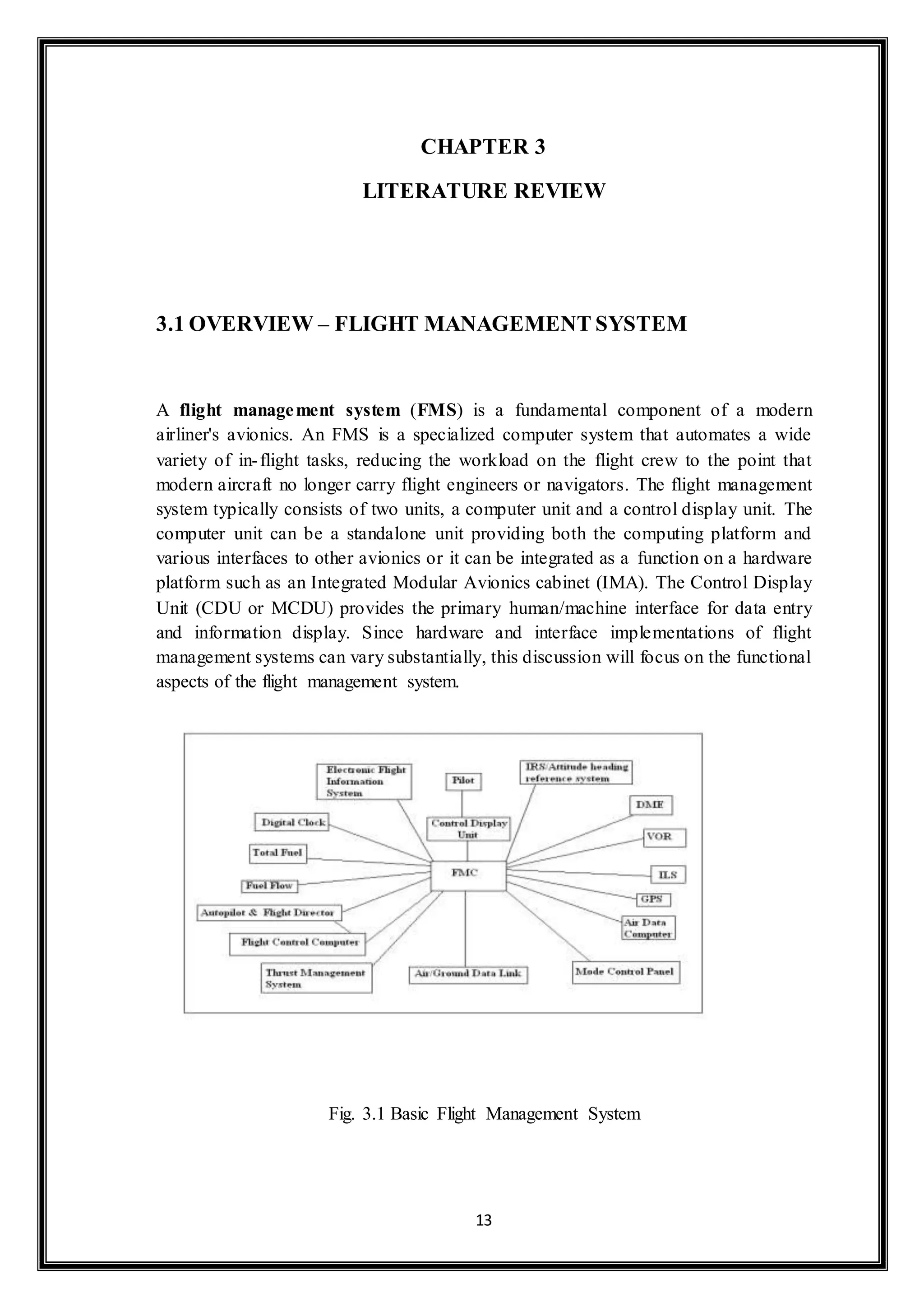
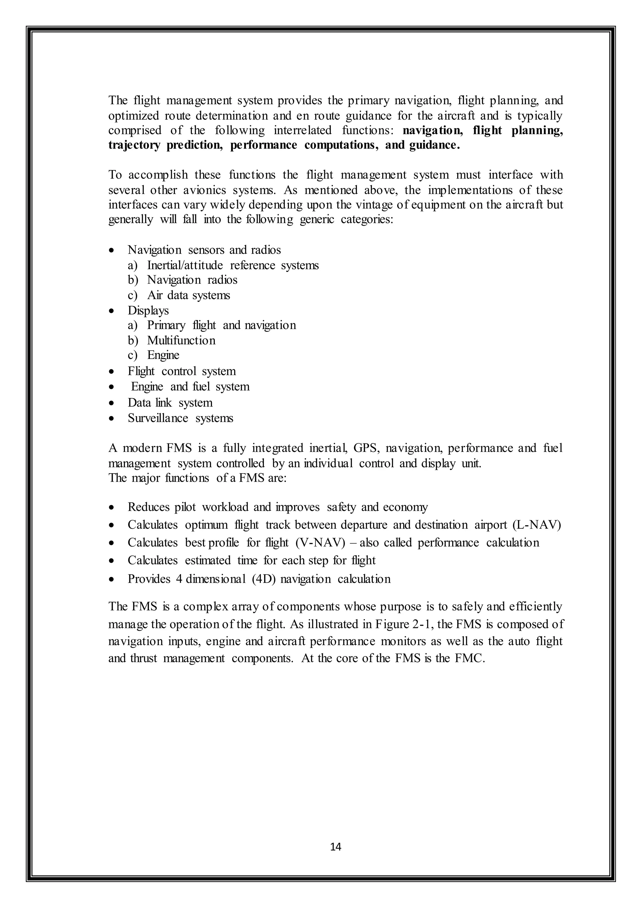
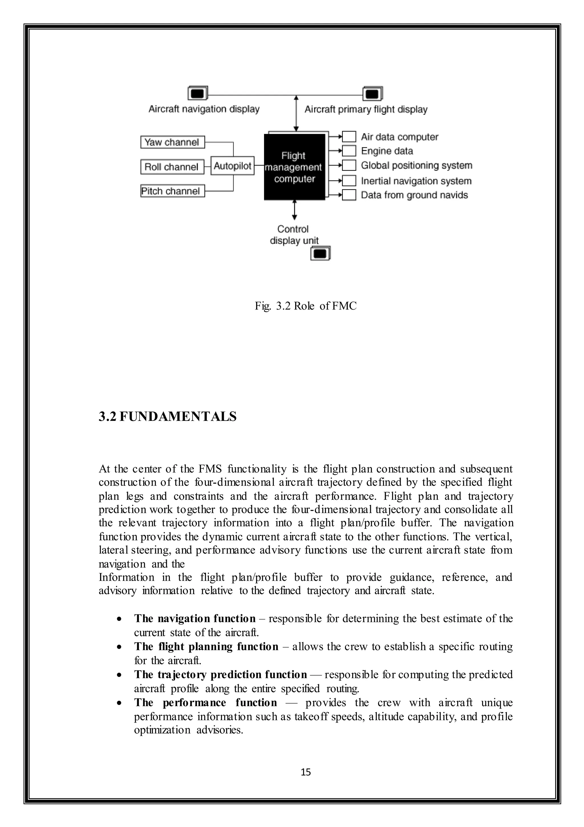
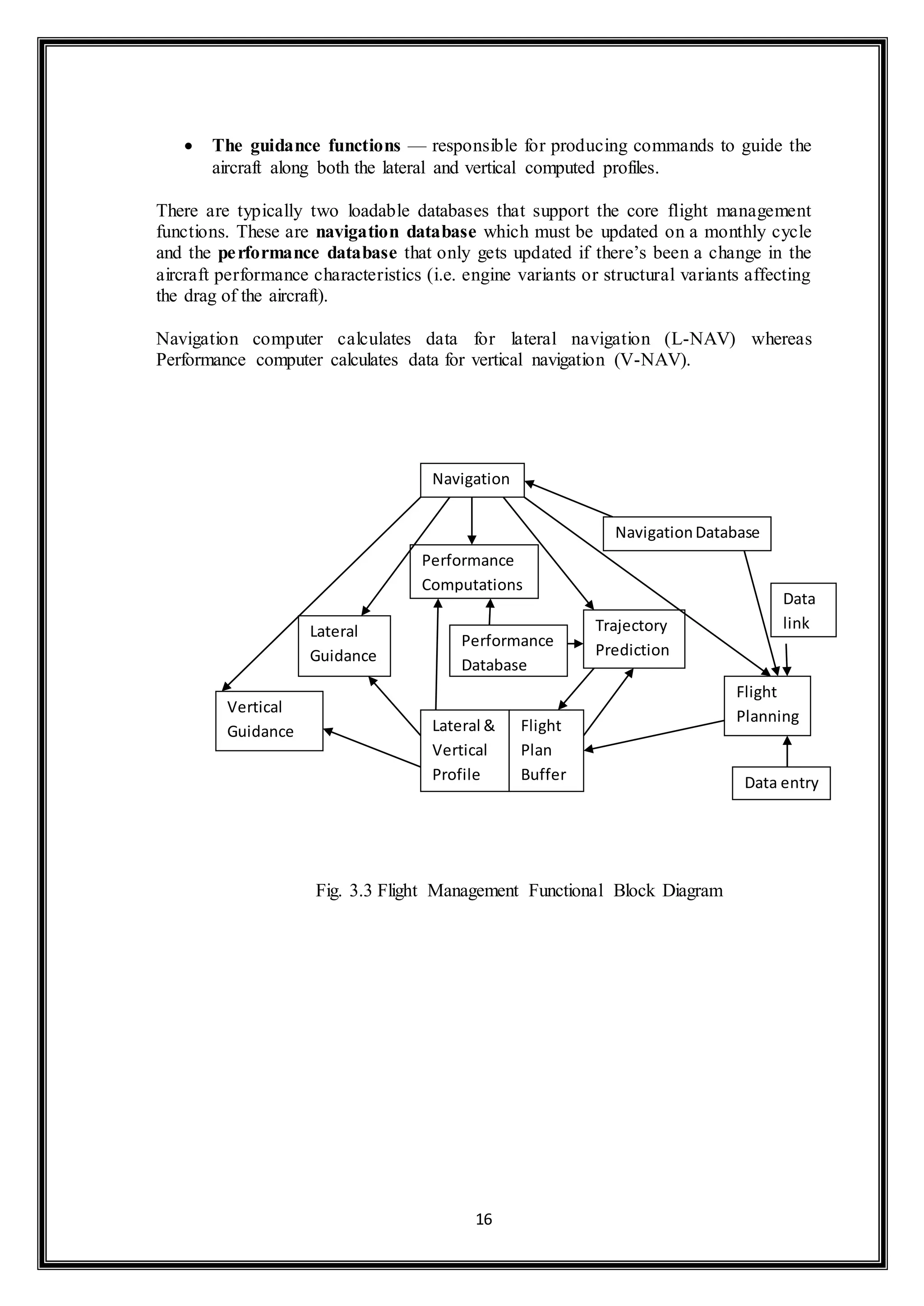
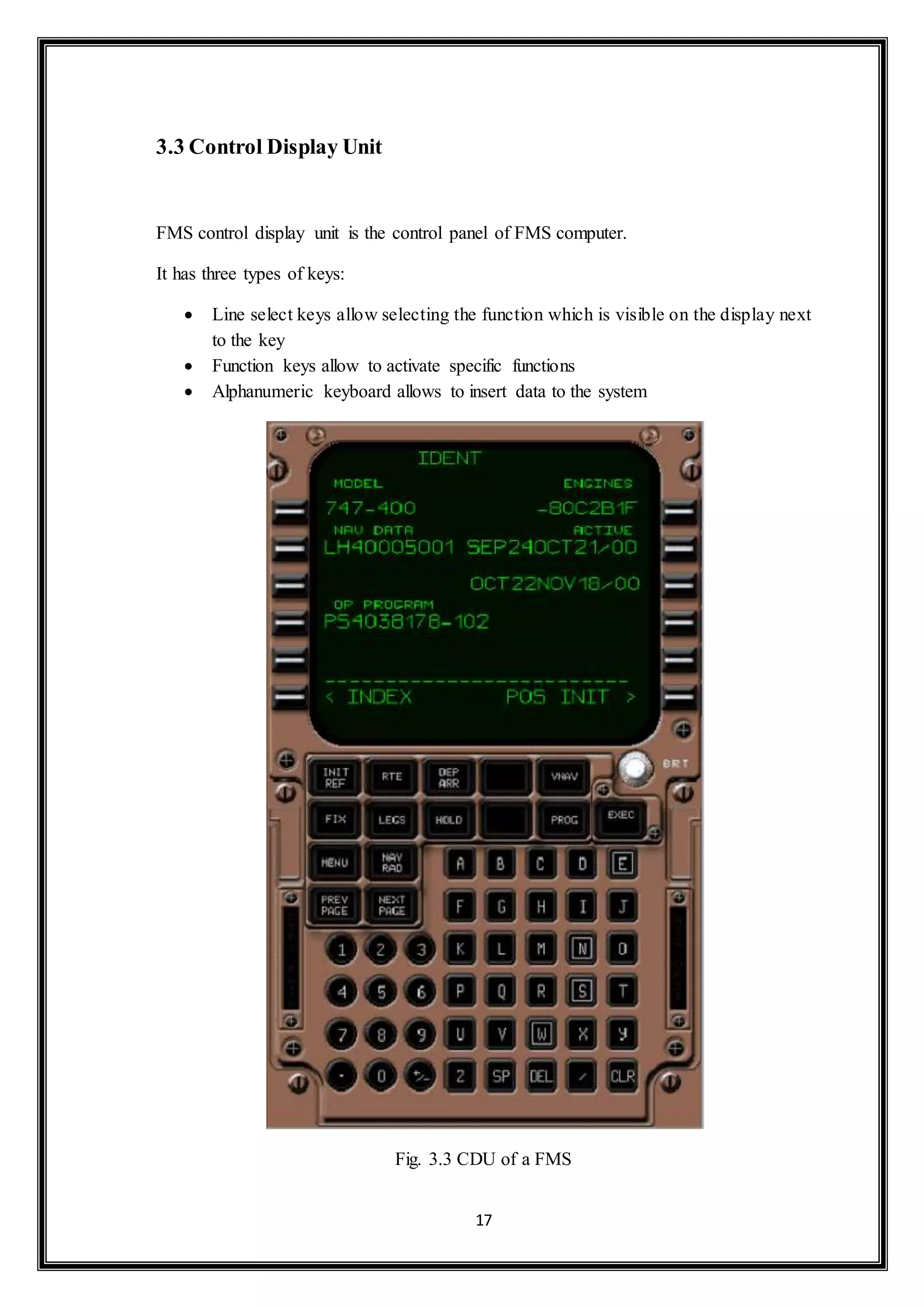
An FMS is a computer system that automates many flight tasks, reducing crew workload. It helps navigate the aircraft along the flight plan using sensors like GPS. From the cockpit, the FMS is controlled through a display unit with a screen and keyboard. The FMS calculates the optimal flight route and sends the flight plan to displays. Modern FMS units integrate navigation, performance, and fuel management and are controlled through a single display unit.
A Technical Study and Industrial Report on the various Electrical and Communication Systems used in choppers manufactured and Overhauled by Hindustan Aeronautics Limited.
INDUSTRIAL TRAINING AT HINDUSTAN AERONAUTICS LIMITED, LUCKNOWAdrija Chowdhury
reviewed overall ACCESSORIES DIVISION, HAL, LUCKNOW. Emphasized major points on HAL history, their motto...how the industrial training can be fruitful to the aspiring engineers
This is a Summer Internship Report submitted by RAHUL KUMAR pursuing B.tech in Mechanical Engineering from Dr. A P J Abdul Kalam Technical University. Student done his internship from HAL Lucknow.
Blended Wing Body (BWB) - Future Of AviationAsim Ghatak
What is Blended Wing Body, History, Advantages And Disadvantages, Design and Structure, How airplanes Fly, Conventional airplanes vs. BWB, Future Scope And Challenges.
This is a power point intended to allow groups to talk about space considerations when building or changing their museum building. It is only an orientation and not a complete one but gets staff to understand that architectural space planning is really a common sense narrative that they can accomplish with the aid of a sympathetic architect.
The great challenge to museum architecture lies in providing for the often conflicting uses of the building. On one hand, the important objects in the collection must be preserved, and preservation often requires very specific environments. On the other hand, museums make parts of their collection available to the public, so the environment must be comfortable for people, enabling their movement through the space and providing for their safety.
COLLEGE BUS MANAGEMENT SYSTEM PROJECT REPORT.pdfKamal Acharya
The College Bus Management system is completely developed by Visual Basic .NET Version. The application is connect with most secured database language MS SQL Server. The application is develop by using best combination of front-end and back-end languages. The application is totally design like flat user interface. This flat user interface is more attractive user interface in 2017. The application is gives more important to the system functionality. The application is to manage the student’s details, driver’s details, bus details, bus route details, bus fees details and more. The application has only one unit for admin. The admin can manage the entire application. The admin can login into the application by using username and password of the admin. The application is develop for big and small colleges. It is more user friendly for non-computer person. Even they can easily learn how to manage the application within hours. The application is more secure by the admin. The system will give an effective output for the VB.Net and SQL Server given as input to the system. The compiled java program given as input to the system, after scanning the program will generate different reports. The application generates the report for users. The admin can view and download the report of the data. The application deliver the excel format reports. Because, excel formatted reports is very easy to understand the income and expense of the college bus. This application is mainly develop for windows operating system users. In 2017, 73% of people enterprises are using windows operating system. So the application will easily install for all the windows operating system users. The application-developed size is very low. The application consumes very low space in disk. Therefore, the user can allocate very minimum local disk space for this application.
Immunizing Image Classifiers Against Localized Adversary Attacksgerogepatton
This paper addresses the vulnerability of deep learning models, particularly convolutional neural networks
(CNN)s, to adversarial attacks and presents a proactive training technique designed to counter them. We
introduce a novel volumization algorithm, which transforms 2D images into 3D volumetric representations.
When combined with 3D convolution and deep curriculum learning optimization (CLO), itsignificantly improves
the immunity of models against localized universal attacks by up to 40%. We evaluate our proposed approach
using contemporary CNN architectures and the modified Canadian Institute for Advanced Research (CIFAR-10
and CIFAR-100) and ImageNet Large Scale Visual Recognition Challenge (ILSVRC12) datasets, showcasing
accuracy improvements over previous techniques. The results indicate that the combination of the volumetric
input and curriculum learning holds significant promise for mitigating adversarial attacks without necessitating
adversary training.
Welcome to WIPAC Monthly the magazine brought to you by the LinkedIn Group Water Industry Process Automation & Control.
In this month's edition, along with this month's industry news to celebrate the 13 years since the group was created we have articles including
A case study of the used of Advanced Process Control at the Wastewater Treatment works at Lleida in Spain
A look back on an article on smart wastewater networks in order to see how the industry has measured up in the interim around the adoption of Digital Transformation in the Water Industry.
CFD Simulation of By-pass Flow in a HRSG module by R&R Consult.pptxR&R Consult
CFD analysis is incredibly effective at solving mysteries and improving the performance of complex systems!
Here's a great example: At a large natural gas-fired power plant, where they use waste heat to generate steam and energy, they were puzzled that their boiler wasn't producing as much steam as expected.
R&R and Tetra Engineering Group Inc. were asked to solve the issue with reduced steam production.
An inspection had shown that a significant amount of hot flue gas was bypassing the boiler tubes, where the heat was supposed to be transferred.
R&R Consult conducted a CFD analysis, which revealed that 6.3% of the flue gas was bypassing the boiler tubes without transferring heat. The analysis also showed that the flue gas was instead being directed along the sides of the boiler and between the modules that were supposed to capture the heat. This was the cause of the reduced performance.
Based on our results, Tetra Engineering installed covering plates to reduce the bypass flow. This improved the boiler's performance and increased electricity production.
It is always satisfying when we can help solve complex challenges like this. Do your systems also need a check-up or optimization? Give us a call!
Work done in cooperation with James Malloy and David Moelling from Tetra Engineering.
More examples of our work https://www.r-r-consult.dk/en/cases-en/
Saudi Arabia stands as a titan in the global energy landscape, renowned for its abundant oil and gas resources. It's the largest exporter of petroleum and holds some of the world's most significant reserves. Let's delve into the top 10 oil and gas projects shaping Saudi Arabia's energy future in 2024.
Democratizing Fuzzing at Scale by Abhishek Aryaabh.arya
Presented at NUS: Fuzzing and Software Security Summer School 2024
This keynote talks about the democratization of fuzzing at scale, highlighting the collaboration between open source communities, academia, and industry to advance the field of fuzzing. It delves into the history of fuzzing, the development of scalable fuzzing platforms, and the empowerment of community-driven research. The talk will further discuss recent advancements leveraging AI/ML and offer insights into the future evolution of the fuzzing landscape.
Hybrid optimization of pumped hydro system and solar- Engr. Abdul-Azeez.pdffxintegritypublishin
Advancements in technology unveil a myriad of electrical and electronic breakthroughs geared towards efficiently harnessing limited resources to meet human energy demands. The optimization of hybrid solar PV panels and pumped hydro energy supply systems plays a pivotal role in utilizing natural resources effectively. This initiative not only benefits humanity but also fosters environmental sustainability. The study investigated the design optimization of these hybrid systems, focusing on understanding solar radiation patterns, identifying geographical influences on solar radiation, formulating a mathematical model for system optimization, and determining the optimal configuration of PV panels and pumped hydro storage. Through a comparative analysis approach and eight weeks of data collection, the study addressed key research questions related to solar radiation patterns and optimal system design. The findings highlighted regions with heightened solar radiation levels, showcasing substantial potential for power generation and emphasizing the system's efficiency. Optimizing system design significantly boosted power generation, promoted renewable energy utilization, and enhanced energy storage capacity. The study underscored the benefits of optimizing hybrid solar PV panels and pumped hydro energy supply systems for sustainable energy usage. Optimizing the design of solar PV panels and pumped hydro energy supply systems as examined across diverse climatic conditions in a developing country, not only enhances power generation but also improves the integration of renewable energy sources and boosts energy storage capacities, particularly beneficial for less economically prosperous regions. Additionally, the study provides valuable insights for advancing energy research in economically viable areas. Recommendations included conducting site-specific assessments, utilizing advanced modeling tools, implementing regular maintenance protocols, and enhancing communication among system components.
Cosmetic shop management system project report.pdfKamal Acharya
Buying new cosmetic products is difficult. It can even be scary for those who have sensitive skin and are prone to skin trouble. The information needed to alleviate this problem is on the back of each product, but it's thought to interpret those ingredient lists unless you have a background in chemistry.
Instead of buying and hoping for the best, we can use data science to help us predict which products may be good fits for us. It includes various function programs to do the above mentioned tasks.
Data file handling has been effectively used in the program.
The automated cosmetic shop management system should deal with the automation of general workflow and administration process of the shop. The main processes of the system focus on customer's request where the system is able to search the most appropriate products and deliver it to the customers. It should help the employees to quickly identify the list of cosmetic product that have reached the minimum quantity and also keep a track of expired date for each cosmetic product. It should help the employees to find the rack number in which the product is placed.It is also Faster and more efficient way.
Overview of the fundamental roles in Hydropower generation and the components involved in wider Electrical Engineering.
This paper presents the design and construction of hydroelectric dams from the hydrologist’s survey of the valley before construction, all aspects and involved disciplines, fluid dynamics, structural engineering, generation and mains frequency regulation to the very transmission of power through the network in the United Kingdom.
Author: Robbie Edward Sayers
Collaborators and co editors: Charlie Sims and Connor Healey.
(C) 2024 Robbie E. Sayers
Final project report on grocery store management system..pdfKamal Acharya
In today’s fast-changing business environment, it’s extremely important to be able to respond to client needs in the most effective and timely manner. If your customers wish to see your business online and have instant access to your products or services.
Online Grocery Store is an e-commerce website, which retails various grocery products. This project allows viewing various products available enables registered users to purchase desired products instantly using Paytm, UPI payment processor (Instant Pay) and also can place order by using Cash on Delivery (Pay Later) option. This project provides an easy access to Administrators and Managers to view orders placed using Pay Later and Instant Pay options.
In order to develop an e-commerce website, a number of Technologies must be studied and understood. These include multi-tiered architecture, server and client-side scripting techniques, implementation technologies, programming language (such as PHP, HTML, CSS, JavaScript) and MySQL relational databases. This is a project with the objective to develop a basic website where a consumer is provided with a shopping cart website and also to know about the technologies used to develop such a website.
This document will discuss each of the underlying technologies to create and implement an e- commerce website.
Automobile Management System Project Report.pdfKamal Acharya
The proposed project is developed to manage the automobile in the automobile dealer company. The main module in this project is login, automobile management, customer management, sales, complaints and reports. The first module is the login. The automobile showroom owner should login to the project for usage. The username and password are verified and if it is correct, next form opens. If the username and password are not correct, it shows the error message.
When a customer search for a automobile, if the automobile is available, they will be taken to a page that shows the details of the automobile including automobile name, automobile ID, quantity, price etc. “Automobile Management System” is useful for maintaining automobiles, customers effectively and hence helps for establishing good relation between customer and automobile organization. It contains various customized modules for effectively maintaining automobiles and stock information accurately and safely.
When the automobile is sold to the customer, stock will be reduced automatically. When a new purchase is made, stock will be increased automatically. While selecting automobiles for sale, the proposed software will automatically check for total number of available stock of that particular item, if the total stock of that particular item is less than 5, software will notify the user to purchase the particular item.
Also when the user tries to sale items which are not in stock, the system will prompt the user that the stock is not enough. Customers of this system can search for a automobile; can purchase a automobile easily by selecting fast. On the other hand the stock of automobiles can be maintained perfectly by the automobile shop manager overcoming the drawbacks of existing system.
Quality defects in TMT Bars, Possible causes and Potential Solutions.PrashantGoswami42
Maintaining high-quality standards in the production of TMT bars is crucial for ensuring structural integrity in construction. Addressing common defects through careful monitoring, standardized processes, and advanced technology can significantly improve the quality of TMT bars. Continuous training and adherence to quality control measures will also play a pivotal role in minimizing these defects.
About
Indigenized remote control interface card suitable for MAFI system CCR equipment. Compatible for IDM8000 CCR. Backplane mounted serial and TCP/Ethernet communication module for CCR remote access. IDM 8000 CCR remote control on serial and TCP protocol.
• Remote control: Parallel or serial interface.
• Compatible with MAFI CCR system.
• Compatible with IDM8000 CCR.
• Compatible with Backplane mount serial communication.
• Compatible with commercial and Defence aviation CCR system.
• Remote control system for accessing CCR and allied system over serial or TCP.
• Indigenized local Support/presence in India.
• Easy in configuration using DIP switches.
Technical Specifications
Indigenized remote control interface card suitable for MAFI system CCR equipment. Compatible for IDM8000 CCR. Backplane mounted serial and TCP/Ethernet communication module for CCR remote access. IDM 8000 CCR remote control on serial and TCP protocol.
Key Features
Indigenized remote control interface card suitable for MAFI system CCR equipment. Compatible for IDM8000 CCR. Backplane mounted serial and TCP/Ethernet communication module for CCR remote access. IDM 8000 CCR remote control on serial and TCP protocol.
• Remote control: Parallel or serial interface
• Compatible with MAFI CCR system
• Copatiable with IDM8000 CCR
• Compatible with Backplane mount serial communication.
• Compatible with commercial and Defence aviation CCR system.
• Remote control system for accessing CCR and allied system over serial or TCP.
• Indigenized local Support/presence in India.
Application
• Remote control: Parallel or serial interface.
• Compatible with MAFI CCR system.
• Compatible with IDM8000 CCR.
• Compatible with Backplane mount serial communication.
• Compatible with commercial and Defence aviation CCR system.
• Remote control system for accessing CCR and allied system over serial or TCP.
• Indigenized local Support/presence in India.
• Easy in configuration using DIP switches.
1. FLIGHT MANAGEMENT SYSTEM
ABSTRACT
A flight management system (FMS) is a fundamental component of a modern
airliner's avionics. An FMS is a specialized computer system that automates a wide
variety of in-flight tasks, reducing the workload on the flight crew to the point that
modern aircraft no longer carry flight engineers or navigators. It helps in air traffic
control. A primary function is in-flight management of the flight plan. Using various
sensors (such as GPS and INS often backed up by radio navigation) to determine the
aircraft's position, the FMS can guide the aircraft along the flight plan. From the
cockpit, the FMS is normally controlled through a Control Display Unit (CDU) which
incorporates a small screen and keyboard or touch screen. The FMS sends the flight
plan for display on the EFIS, Navigation Display (ND) or Multifunction Display
(MFD).
The modern FMS was introduced on the Boeing 767, though earlier navigation
computers did exist. Now, systems similar to FMS exist on aircraft as small as the
Cessna 182. In its evolution an FMS has had many different sizes, capabilities and
controls.
A modern FMS is a fully integrated inertial, GPS, navigation, performance and fuel
management system controlled by an individual control and display unit.
Keywords: Flight Management System, Control Display Unit, Air Traffic Control
1
2. CHAPTER 1
INTRODUCTION
2
1.1 HISTORY OF HAL
Hindustan Aeronautics Limited (HAL) came into existence on 1st Octobe r
1964. The Company was formed by the merger of Hindustan Aircraft Limited with
Aeronautics India Limited and Aircraft Manufacturing Depot, Kanpur.
The Company traces its roots to the pioneering efforts of an industrialist with
extraordinary vision, the late Seth Walchand Hirachand, who set up Hindustan Aircraft
Limited at Bangalore in association with the erstwhile princely State of Mysore in
December 1940. The Government of India became a shareholder in March 1941 and
took over the Management in 1942.
Today, HAL has 19 Production Units and 10 Research & Design Centres in 8 locations
in India. The Company has an impressive product track record - 15 types of
Aircraft/Helicopters manufactured with in-house R & D and 14 types produced under
license. Hal has manufactured over 3658 aircrafts/helicopters, 4178 engines,
upgraded 272 aircrafts and overhauled over 9643 aircrafts and 29775 engines.
HAL has been successful in numerous R & D programs developed for both Defence
and Civil Aviation sectors.
HAL has made substantial progress in its current projects :
Advanced Light Helicopter – Weapon System Integration (ALH-WSI)
Tejas - Light Combat Aircraft (LCA)
Intermediate Jet Trainer (IJT)
Light Combat Helicopter (LCH)
Various military and civil upgrades.
HAL has formed the following Joint Ventures (JVs) :
BAeHAL Software Limited
Indo-Russian Aviation Limited (IRAL)
Snecma
3. SAMTEL-HAL Display System Limited
3
HALBIT Avionics Pvt Ltd
HAL-Edgewood Technologies Pvt Ltd
INFOTECH-HAL Ltd
TATA-HAL Technologies Ltd
HATSOFF Helicopter Training Pvt Ltd
International Aerospace Manufacturing Pvt Ltd
Multi Role Transport Aircraft Ltd
Several Co-production and Joint Ventures with international participation are under
consideration.
HAL's supplies / services are mainly to Indian Defence Services, Coast Guard and
Border Security Force. Transport Aircraft and Helicopters have also been supplied to
Airlines as well as State Governments of India. The Company has also achieved a
foothold in export in more than 30 countries, having demonstrated its quality and price
competitiveness.
HAL was confe rred NAVRATNA status by the Government of India on 22nd
June 2007.
The Company scaled new heights in the Financial Year 2010-11 with Turnover of
Rs.13, 116 Crores and PBT of Rs 2,841 Crores.
HAL has won several International & National Awards for achievements in R&D,
Technology, Managerial Performance, Exports, Energy Conservation, Quality
and fulfillment of Social Responsibilities.
There are several divisions under Hindustan Aeronautical Limited. They are as under:
BANGLORE COMPLEX
Aircraft Division Bangalore
Overhaul Division Bangalore
Aerospace Division Bangalore
Aircraft Services Division Bangalore
Engine Division Bangalore
Foundry and Forge Division Bangalore
IGMT Division Bangalore
Facilities Management Division Bangalore
4. 4
Mig COMPLEX
Aircraft Division Nasik
Engine Division Koraput
Aircraft Overhaul Division Nasik
Sukhoi Engine Division Koraput
ACCESSORIES COMPLEX
TAD-Kanpur Division
Accessories Division Lucknow
Avionics Division Hyderabad
Avionics Division Korwa
HELICOPTER COMPLEX
Helicopter Division Bangalore
Helicopter MRO Division Bangalore
Barrackpore Division
CMD Division Bangalore
1.2 PRESENT SETUP OF LUCKNOW DIVISION
Accessories Division of HAL was established in 1970 with the primary objective of
manufacturing systems and accessories for various aircraft and engines and attain self
sufficiency in this area. Its facilities are spread over 116,000 sqm of built area set in
sylvan surroundings. At present it is turning out over 1300 different types of
accessories. The Division started with manufacturing various Systems and Accessories
viz, Hydraulics, Engine Fuel System, Air-conditioning and Pressurization, Flight
Control, Wheel and Brake, Gyro & Barometric Instruments, Electrical and Power
Generation & Control System, Undercarriages, Oxygen System and Electronic System
all under one roof to meet the requirements of the aircraft, helicopters and engines
being produced by HAL like MiG series of aircrafts, Dornier, Jaguar, Advanced Light
Helicopters(ALH), PTA, Cheetah & Su-30 and repair / Overhaul of Avro, AN-32,
HPT-32, Mirage-2000 & Sea-Harrier aircrafts, Cheetah and Chetak helicopters.
The Division undertakes manufacturing and serviceing of accessories under Transfer of
Technology (ToT) from more than 40 licensor from different countries. In addition, a
lot of emphasis has been given on developing indigenous capability for Design and
Development of various systems and accessories. This capability has culminated in
indigenous design and development of over 350 types of accessories for the Light
Combat Aircraft (LCA) (Air force and Navy version), Advanced Light Helicopter (all
5. versions i.e. Army, Air force, Navy & Civil), SARAS and IJT (Intermediate Jet
Trainer). The Division has also developed and has made successful strides into the area
of Microprocessor based control systems for the LCA Engine as well as other systems.
The Division has been in the forefront of accessories development and supply not only
to Indian Force but to Army, Navy, Coast Guard and various Defence Laboratories as
well as for Space applications.
The Division is networked with all sister Divisions and R& D Centers by LAN/WAN.
Lean manufacturing and ERP have been implemented to create an efficient
manufacturing system.
The Division today has a prime name in the Aviation market and various international
companies are interested to join hands with it for future projects. The Division has also
made steady progress in the area of Export.
1.2.1 PRODUCTION OF LUCKNOW DIVISION
Products in Current Manufacturing Range
HYDRAULIC SYSTEM AND POWER CONTROL
Hydraulic Pumps, Accumulators, Actuators, Electro-selectors, Bootstrap
Reservoirs and various types of valves
ENVIRONMENTAL CONTROL SYSTEM
Cold Air Unit, Water Extractors, Non Return Valves and Venturies
ENGINE FUEL CONTROL SYSTEM
Fuel after Burner regulator and distributor, Main Fuel Distributor, Regulator
and After Burner Pump, Plunger Pumps, Fuel Metering Device
5
INSTRUMENTS
Electrical Indicators, Fuel quantity and flow metering instruments, Flight
instruments, Sensors and Switches
ELECTRICAL POWER GENERATION AND CONTROL SYSTEM
6. AC/DC Generator, Control and Protection Units, AC and DC Master Box,
Inverters, Transformer Rectifier Unit, Actuators
UNDERCARRIAGE, WHEELS AND BRAKES
Main and Nose Undercarriage, Main and Nose Wheel, Brake System LRUs
6
TEST RIGS
Dedicated Test Rigs, custom-built Fuel/Hydraulic Test Rigs and Electrical Test
Rigs.
Export Products
Supply of New along with Repair and Overhaul of Rotables and Spares of
aircraft accessories of MiG series, Jaguar International, Light Combat Aircraft
(LCA), Su-30 MKI, Mirage-2000, Sea Harrier, Dornier DO-228, Avro HS-748
(Specific Version), Cheetah (Lama) / Chetak (Alouette III), MI - 17, Advanced
Light Helicopter (ALH) Helicopters to Royal Air Force Oman, Air Mauritius,
Israel Aircraft Industries, ELTA Israel, Hamilton Susstrand U.S.A., Govt of
Namibia, Aerostar Romania, Ecuadorian Air Force etc.
Customers
Indian Air Force / Army / Navy / Coast Guard
Defence R&D Laboratories / Department of Space
State Govt. Civil Aviation / Ordnance Factories / Corporate Sectors
Flying Academics & Educational Institutions
Airlines / Air Taxi / Air Cargo
Defence Forces of countries from South East Asia, Middle East and Africa
Collaborators / Licensors
1.2.2 SERVICES OF LUCKNOW DIVISION
The Division carries out Repair and Overhaul of Accessories, with minimum turn-around-
time. Site Repair facilities are offered by the Division by deputing team of
expert Engineers / Technicians.
7. 7
Services provided for:
Military Aircraft
MiG Series
Jaguar
Mirage-2000
Sea - Harrier
AN-32
Kiran MK- I / MK- II
HPT - 32
SU-30 MKI
Civil Aircraft
Dornier-22B
AVRO HS-748
Helicopters
Chetak (Alouette)
Cheetah (Lama)
ALH (IAF / NAVY / COAST GUARD / CIVIL)
Sub-contract Capabilities
The Division has comprehensive manufacturing capabilities for various Hi-tech
components, Equipment and Systems to customer's specifications and ensures
high quality, reliability and cost effectiveness.
The Division has over 40 years of experience in producing aeronautical
accessories making it an ideal partner for the International Aero Engineering
Industry.
The Division also manufactures and supplies complete range of components of Cheetah
(Lama) & Chetak (Alouette) Helicopters, Jaguar and MiG series Aircraft to Domestic
and International Customers to support their fleet.
8. CHAPTER 2
2.1 PRODUCTS MADE BY H.A.L. LUCKNOW
HYDRAULIC PUMP STARTER GENERATOR
MAIN ROTOR ACTUATOR
OTHER ACCESSORIES
8
9. 2.2 PRODUCTS IN CURRENT MANUFACTURING RANGE
Su 30 MKi MiG-27 M
MiG 21 Variants metallic drop tanks
Under carriage ejection seats
Canopy flexible rubber fuel tank
9
11. 2.4 PRODUCTS OF AEROSPACE DIVISION
2.4.1 PSLV: (POLAR SATELLITE LAUNCH VEHICLE)
No. Of Stages 4-Stage Rocket With Two Solid & Two
Liquid Stages With 6 Strap-on Motors
Orbit Low Earth Polar Orbit 900 km
Mission Inject 1000-1200 Kg Class Satellite (IRS) In
11
Polar Orbit
2.4.2 GSLV: (GEO-SYCHRONOUS SATELLITE LAUNCH VEHICLE) MK II
No. Of Stages 3-Stage Rocket with Solid, Liquid and Cryo
Stages with 4 Strap-on Motors
Orbit Geo-Stationary Orbit 36000 km
Mission Inject 2500 Kg Satellite INSAT Series in
Geo-Synchronous Orbit
2.4.3 GSLV: (GEO-SYCHRONOUS SATELLITE LAUNCH VEHICLE) MK III
No. Of Stages 2-Stage with Liquid and Cryo Stages and 2
Strap-on Motors
Orbit Geo-Synchronous Orbit 36000 km
Mission Inject 4500 – 5000 Kg INSAT Class
Satellite, in Geo-Synchronous Orbit
2.4.4 INDIAN REMOTE SENSING SATELLITE
Mission Resource Survey & Management In the area
of Agriculture, Forestry, Hydrology & Snow
Melting.
Launch Vehicle PSLV
Orbit Low Earth Polar Orbit 900 km
Life 5 Years
12. 2.4.5 INDIAN NATIONAL SATELLITE
Mission National Tele-communication, TV
Broadcasting, Radio Net Working,
Meteorological Observation Satellite Aided
Research & Rescue
Launch Vehicle GSLV
Orbit Geo-Stationary Orbit 36000 km
Life 7 Years
12
13. CHAPTER 3
LITERATURE REVIEW
3.1 OVERVIEW – FLIGHT MANAGEMENT SYSTEM
A flight management system (FMS) is a fundamental component of a modern
airliner's avionics. An FMS is a specialized computer system that automates a wide
variety of in- flight tasks, reducing the workload on the flight crew to the point that
modern aircraft no longer carry flight engineers or navigators. The flight management
system typically consists of two units, a computer unit and a control display unit. The
computer unit can be a standalone unit providing both the computing platform and
various interfaces to other avionics or it can be integrated as a function on a hardware
platform such as an Integrated Modular Avionics cabinet (IMA). The Control Display
Unit (CDU or MCDU) provides the primary human/machine interface for data entry
and information display. Since hardware and interface implementations of flight
management systems can vary substantially, this discussion will focus on the functional
aspects of the flight management system.
Fig. 3.1 Basic Flight Management System
13
14. The flight management system provides the primary navigation, flight planning, and
optimized route determination and en route guidance for the aircraft and is typically
comprised of the following interrelated functions: navigation, flight planning,
trajectory prediction, performance computations, and guidance.
To accomplish these functions the flight management system must interface with
several other avionics systems. As mentioned above, the implementations of these
interfaces can vary widely depending upon the vintage of equipment on the aircraft but
generally will fall into the following generic categories:
14
Navigation sensors and radios
a) Inertial/attitude reference systems
b) Navigation radios
c) Air data systems
Displays
a) Primary flight and navigation
b) Multifunction
c) Engine
Flight control system
Engine and fuel system
Data link system
Surveillance systems
A modern FMS is a fully integrated inertial, GPS, navigation, performance and fuel
management system controlled by an individual control and display unit.
The major functions of a FMS are:
Reduces pilot workload and improves safety and economy
Calculates optimum flight track between departure and destination airport (L-NAV)
Calculates best profile for flight (V-NAV) – also called performance calculation
Calculates estimated time for each step for flight
Provides 4 dimensional (4D) navigation calculation
The FMS is a complex array of components whose purpose is to safely and efficiently
manage the operation of the flight. As illustrated in Figure 2-1, the FMS is composed of
navigation inputs, engine and aircraft performance monitors as well as the auto flight
and thrust management components. At the core of the FMS is the FMC.
15. Fig. 3.2 Role of FMC
15
3.2 FUNDAMENTALS
At the center of the FMS functionality is the flight plan construction and subsequent
construction of the four-dimensional aircraft trajectory defined by the specified flight
plan legs and constraints and the aircraft performance. Flight plan and trajectory
prediction work together to produce the four-dimensional trajectory and consolidate all
the relevant trajectory information into a flight plan/profile buffer. The navigation
function provides the dynamic current aircraft state to the other functions. The vertical,
lateral steering, and performance advisory functions use the current aircraft state from
navigation and the
Information in the flight plan/profile buffer to provide guidance, reference, and
advisory information relative to the defined trajectory and aircraft state.
The navigation function – responsible for determining the best estimate of the
current state of the aircraft.
The flight planning function – allows the crew to establish a specific routing
for the aircraft.
The trajectory prediction function — responsible for computing the predicted
aircraft profile along the entire specified routing.
The performance function — provides the crew with aircraft unique
performance information such as takeoff speeds, altitude capability, and profile
optimization advisories.
16. The guidance functions — responsible for producing commands to guide the
aircraft along both the lateral and vertical computed profiles.
There are typically two loadable databases that support the core flight management
functions. These are navigation database which must be updated on a monthly cycle
and the pe rformance database that only gets updated if there’s been a change in the
aircraft performance characteristics (i.e. engine variants or structural variants affecting
the drag of the aircraft).
Navigation computer calculates data for lateral navigation (L-NAV) whereas
Performance computer calculates data for vertical navigation (V-NAV).
Navigation
16
Navigation Database
Performance
Computations
Performance
Database
Trajectory
Prediction
Flight
Planning
Lateral &
Vertical
Profile
Flight
Plan
Buffer
Lateral
Guidance
Vertical
Guidance
Data
link
Data entry
Fig. 3.3 Flight Management Functional Block Diagram
17. 17
3.3 Control Display Unit
FMS control display unit is the control panel of FMS computer.
It has three types of keys:
Line select keys allow selecting the function which is visible on the display next
to the key
Function keys allow to activate specific functions
Alphanumeric keyboard allows to insert data to the system
Fig. 3.3 CDU of a FMS
18. Color code is used to display information on the FMS display (CDU) :
PARAMETER COLOR
Vertical data Blue (Cyan)
Atmospheric data
Lateral data Green
Index selection
FROM waypoint Yellow
TO waypoint Purple (Magenta)
Prompts and Titles White
Flight plan names Orange (Amber)
18
3.4 NAVIGATION DATABASE
All FMS contain a navigation database. The navigation database contains the elements
from which the flight plan is constructed. These are defined via the ARINC 424
standard. The navigation database (NDB) is normally updated every 28 days, in order
to ensure that its contents are current. Each FMS contains only a subset of the ARINC
data, relevant to the capabilities of the FMS.
The NDB contains all of the information required for building a flight plan, consisting
of:
Waypoints/Intersection
Airways (highways in the sky)
Radio navigation aids including distance measuring equipment (DME), VHF
omni directional range (VOR), non-directional beacons (NDBs) and instrument
landing systems (ILSs).
Airports
Runways
Standard instrument departure (SID)
Standard terminal arrival (STAR)
Holding patterns (only as part of IAPs-although can be entered by command of
ATC or at pilot's discretion)
Instrument approach procedure (IAP)
Waypoints can also be defined by the pilot(s) along the route or by reference to other
waypoints with entry of a place in the form of a waypoint (e.g. a VOR, NDB, ILS,
airport or waypoint/intersection).
19. 19
3.5 L-NAV
Navigation computer of FMC uses navigation database to store navigation data for
flight operation. This database is updated every 28 days by maintenance organization.
Navigation computer creates flight plan and gives desired position for all steps of
flight, for input pilot must enter company route on CDU.
Desired position from flight plan will be compared to the current position, this gives us
the position error which will be sent to AP/FD computer as NAV steering signal.
Autopilot uses this signal to change aircraft movement around three axes.
FMC calculates present positions from signals of different sensors: GPS, IRS, VOR,
ILS, etc. Present position of aircraft is given by IRS, starting position of the aircraft
must be selected from FMS during IRS alignment. During flight IRS position corrected
by GPS and if necessary navigation radios- DME, VOR, LOC all these stations will be
automatically tuned by FMS.
FMS data presented on EFIS Navigation Display uses aircraft symbol shows present
position in relation to flight plan.
L-NAV produces roll steering command to the autopilot.
3.6 V-NAV
Task of vertical navigation part of FMS is:
To optimize vertical flight profile
To calculate optimum speed for each flight phase
To calculate necessary thrust for engines (thrust limit calculation)
Necessary aircraft and engine performance data is stored in performance database.
Optimum aircraft speed depends on many factors:
Environmental conditions – air pressure and temperature from ADC
Aircraft weight
Fuel and time costs
Sophisticated aircraft, generally airliners such as the Airbus A320 or Boeing 737 and
larger, have full performance VNAV or Vertical Navigation. The purpose of VNAV is
to predict and optimize the vertical path. Guidance includes control of the pitch axis
and control of the throttle.
In order to have the information necessary to accomplish this, the FMS must have a
20. detailed flight and engine model. With this information, the function can build a
predicted vertical path along the lateral flight plan. This detailed flight model is
generally only available from the aircraft manufacturer.
During pre-flight, the FMS builds the vertical profile. It uses the initial aircraft empty
weight, fuel weight, centre of gravity and initial cruise altitude, plus the lateral flight
plan. A vertical path starts with a climb to cruise altitude. Some SID waypoints have
vertical constraints such as "At or ABOVE 8,000". The climb may use a reduced
thrust(derated) or "FLEX" climb to save stress on the engines. Each must be considered
in the predictions of the vertical profile.
Implementation of an accurate VNAV is difficult and expensive, but it pays off in fuel
savings primarily in cruise and descent. In cruise, where most of the fuel is burned,
there are multiple methods for fuel savings.
As an aircraft burns fuel it gets lighter and can cruise higher where it is generally more
efficient. Step climbs or cruise climbs facilitate this. VNAV can determine where the
step or cruise climbs (where the aircraft drifts up) should occur to minimize fuel
consumption.
Performance optimization allows the FMS to determine the best or most economical
speed to fly in level flight. This is often called the ECON speed. This is based on the
cost index, which is entered to give a weighting between speed and fuel efficiency.
Generally a cost index of 999 gives ECON speeds as fast as possible without
consideration of fuel and a cost index of Zero gives maximum efficiency. ECON mode
is the VNAV speed used by most airliners in cruise.
An ideal idle descent, also known as a “green descent” uses the minimum fuel,
minimizes pollution (both at high altitude and local to the airport) and minimizes local
noise. While most modern FMS of large airliners are capable of idle descents, most air
traffic control systems cannot handle multiple aircraft each using its own optimum
descent path to the airport, at this time. Thus the use of idle descents is minimized by
Air Traffic Control.
20
21. CHAPTER 4
OUTSOURCING
The outsourcing activity started in the Division way back in 2003. Since then Division
has embarked upon selecting and creating base of sub-contractors for outsourcing
precision components, tooling and test equipment. This is required to handle higher
loads of existing and new projects being undertaken in the division.
The outsourcing is done in the following areas:
1. Machining of components involving turning turning, milling, drilling, jig boring,
grinding, centre-less grinding, lapping etc.
2. Machining / Fabrication of tools, jigs and fixtures.
3. Specialized processes like Ion - Nitriding, Tungsten Carbide Coating, Laser Beam
Welding, Electron Beam Welding, Moulding etc.
Apart from the above production work packages, Design work packages are also
outsourced.
The components are classified in various families like A, B & C depending upon the
criticality of the operations. Depending on the capabilities of sub-contractors, tenders
are being issued to respective registered vendors.
Organizations with established facilities & capabilities, willingness to learn and excel
in producing aeronautical quality product are encouraged for outsourcing of
components required for various projects.
21
22. CONCLUSION
This report is an introduction to the several functions that comprise a flight
management system and has focused on the basic functionality and relationships that
are fundamental to understanding the flight management system and its role in the
operations of the aircraft. Clearly, there is a myriad of complexity in implementing
each function that is beyond the scope of this publication.
The future evolution of the flight management system is expected to focus not on the
core functions as described herein, but on the utilization within the aircraft and on the
ground of the fundamental information produced by the flight management system
today. The use of the FMS aircraft state and trajectory intent, within the aircraft and on
the ground, to provide strategic conflict awareness is a significant step toward better
management of the airspace. Communication of the optimized user-preferred
trajectories will lead to more efficient aircraft operation. The full utilization of RNP-based
navigation will increase the capacity of the airspace. Innovative methods to
communicate FMS information and specify flight plan construction with the crew to
make flight management easier to use are expected as well. Clearly, the FMS is a key
system in moving toward the concepts embodied in CNS future airspace.
FMS performs all the calculations and predictions required to determine the most
economical flight profile, either for minimum fuel or minimum time. When coupled to
the automatic flight control system, with lateral and vertical navigation modes engaged
the flight crew act as managers monitoring and entering data as required. Much of the
data presented on the CDU is also displayed in the primary flight displays, aircrafts
with electronic flight instruments have the advantage in that the information is
displayed with colored symbols to identify key features of the flight plan, e.g.
navigation aids, airfields and descent points.
22