


![Liquid fuels and their characteristics:
The liquid fuels can be classified as following
(a)Natural or crude oil, and
(b) Artificial or manufactured oils.
The advantages and disadvantages of liquid fuels can be summarized as following
Advantages
(a)They posses higher calorific value per unit mass than solid fuels.
(b)They burn without dust, ash, clinkers, etc.
(c) Their firing is easier and also fire can be extinguished easily by stopping liquid fuel
supply.
(d)They are easy to transport through pipes.
(e)They can be stored indefinitely without any loss.
(f)They are clean in use and economic to handle.
(g)Loss of heat in chimney is very low due to greater cleanliness.
(h)They require less excess air for complete combustion.
(i)They require less furnace space for combustion.
Disadvantages
(a)The cost of liquid fuel is relatively much higher as compared to solid fuel.
(b)Costly special storage tanks are required for storing liquid fuels.
(c)There is a greater risk of five hazards, particularly, in case of highly inflammable
and volatile liquid fuels.
(d)They give bad odor.
(e)For efficient burning of liquid fuels, specially constructed burners and spraying
apparatus are required.
Gaseous fuels and their characteristics:
Gaseous fuels occur in nature, besides being manufactured from solid and liquid
fuels.
1) Water gas:
A mixture of carbon monoxide and hydrogen gas is commonly known as water
gas. [CO + H2] = Water gas
it is used as a fuel.
PREPARATION:
It is prepared by passing steamover red hot coke.
C + H2O = CO + H2
2) Coal gas:
Coal gas, gaseous mixture—mainly hydrogen, methane, and carbon monoxide—
formed by the destructive distillation (i.e., heating in the absence of air) of](https://image.slidesharecdn.com/fuel-150728065455-lva1-app6892/85/FUEL-LPG-LNG-Coal-Natural-Gas-Nuclear-Fuel-Fuel-Cell-7-320.jpg)


![38 | P a g e
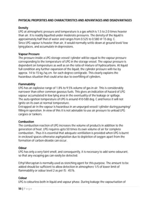
FORM OF NATURAL GAS
There are three form of Natural Gas
1. Normal Natural Gas
2. CNG
3. LNG
Normal Natural Gas:
Natural gas is a naturally occurring hydrocarbon gas mixture consisting primarily of methane,
with other hydrocarbons, carbon dioxide, nitrogen and hydrogen sulfide. Normally it preserve
within 1 bar pressure.
Source:
Natural gas is found in deep underground natural rock formations or associated with other
hydrocarbon reservoirs in coal beds and as methane clathrates. Petroleum is also another
resource found in proximity to and with natural gas.
CNG:
CNG is made by compressing natural gas (which is mainly composed of methane [CH4]), to less
than 1% of the volume it occupies at standard atmospheric pressure.
Compressed natural gas (CNG) is a fossil fuel substitute for gasoline (petrol), diesel, or
propane/LPG. Although its combustion does produce greenhouse gases, it is a more
environmentally clean alternative to those fuels, and it is much safer than other fuels in the
event of a spill (natural gas is lighter than air, and disperses quickly when released). CNG may
also be mixed with biogas, produced from landfills or wastewater, which doesn't increase the
concentration of carbon in the atmosphere.
LNG:
Liquefied natural gas or LNG is natural gas (predominantly methane, CH4) that has been
converted to liquid form for ease of storage or transport. Liquefied natural gas takes up about
1/600th the volume of natural gas in the gaseous state. It is odorless, colorless, non-toxic and
non-corrosive. The liquefaction process involves removal of certain components, such as dust,
acid gases, helium, water, and heavy hydrocarbons, which could cause difficulty downstream.
The natural gas is then condensed into a liquid at close to atmospheric pressure (maximum
transport pressure set at around 25 kPa/3.6 psi) by cooling it to approximately −162 °C (−260
°F).LNG is principally used for transporting natural gas to markets, where it is re-gasified and
distributed as pipeline natural gas. It can be used in natural gas vehicles, although it is more
common to design vehicles to use compressed natural gas. Its relatively high cost of production
and the need to store it in expensive cryogenic tanks have hindered widespread commercial
use but it can emerge as an alternative fuel for heavy duty vehicles like bus, trucks, ships etc.](https://image.slidesharecdn.com/fuel-150728065455-lva1-app6892/85/FUEL-LPG-LNG-Coal-Natural-Gas-Nuclear-Fuel-Fuel-Cell-38-320.jpg)


![82 | P a g e
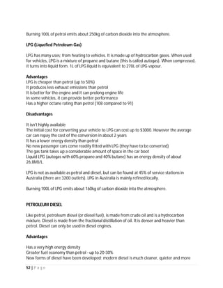
CONVERSIONS
Other heating value unit conversions
Kcal/kg = MJ/kg * 238.846
Btu/lb = MJ/kg * 429.923
Btu/lb = kcals * 1.8
The heat of combustion for fuels is expressed as the HCV, LCV, or GCV.
THEROTICAL DETERMINATION
GROSS CALORIFIC VALUE
The gross calorific value of a substance is the number of heat units that are liberated when a
unit weight of that substance is burned in oxygen, and the residual materials are oxygen,
carbon dioxide, sulphur dioxide, nitrogen, water, and ash. The energy content of biological
materials has been expressed traditionally in calories (c) or kilocalories (C) per gram dry weight.
Sometimes results are expressed more significantly in terms of ash-free dry weight, i.e. in terms
of organic constituents only. Contemporary studies of ecological energetic express results in
terms of the SI energy unit, the joule (4,182 J = 1 calorie).
DULONG’S FORMULA
The first formula for the calculation of theoretical heating values from the composition of a
fuel as determined from an ultimate analysis is due to Dulong, and this formula, slightly
modified, is the most commonly used to-day. Other formulae have been proposed, some of
which are more accurate for certain specific classes of fuel, but all have their basis in
Dulong’s formula, the accepted modified form of which is:
GCV = 1/100 [8080C + 34500(H2 + O2/8) +2240 S] Kcal/Kg
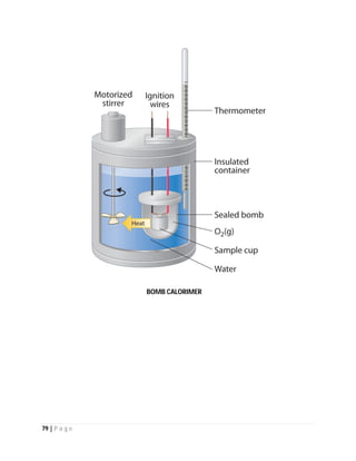
EXPERIMENTAL DETERMINATION
The higher heating value is experimentally determined in a bomb calorimeter. The combustion
of a stoichiometric mixture of fuel and oxidizer (e.g., two moles of hydrogen and one mole of
oxygen) in a steel container at 25° is initiated by an ignition device and the reactions allowed
completing. When hydrogen and oxygen react during combustion, water vapor is produced.
The vessel and its contents are then cooled to the original 25°C and the higher heating value is
determined as the heat released between identical initial and final temperatures.
When the lower heating value (LHV) is determined, cooling is stopped at 150°C and the reaction
heat is only partially recovered. The limit of 150°C is an arbitrary choice.](https://image.slidesharecdn.com/fuel-150728065455-lva1-app6892/85/FUEL-LPG-LNG-Coal-Natural-Gas-Nuclear-Fuel-Fuel-Cell-82-320.jpg)


Natural gas is a combustible mixture of hydrocarbon gases that is primarily composed of methane but can also contain ethane, propane, butane, and pentane. It is formed naturally underground and is considered a nonrenewable fossil fuel. Some key advantages of natural gas are that it is one of the cleanest, safest, and most useful energy sources; it burns cleanly without producing ash or smoke; and it can be transported via pipelines. Natural gas is widely used as a fuel for cooking, heating homes and buildings, generating electricity, fueling vehicles, and various industrial processes.