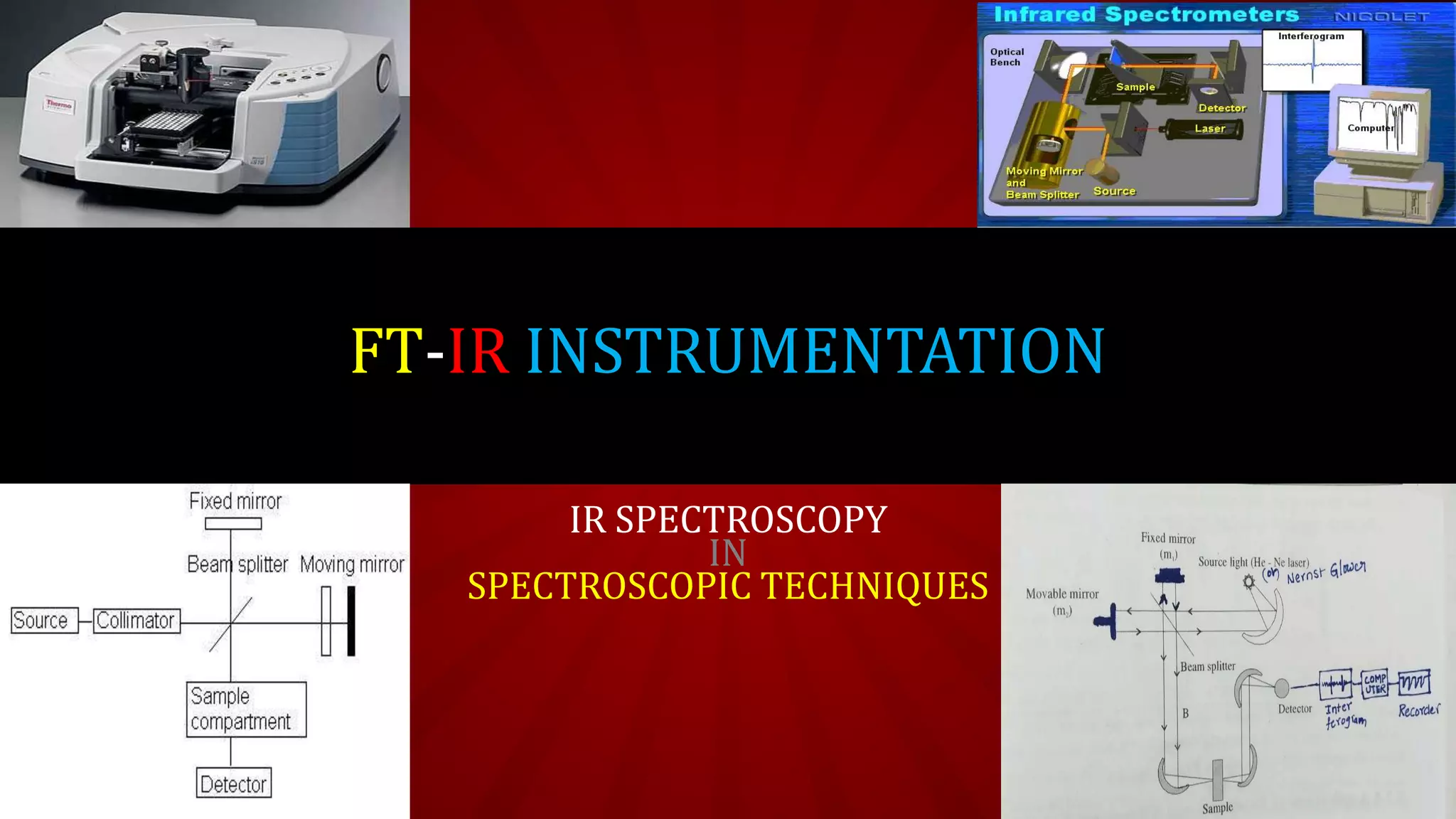
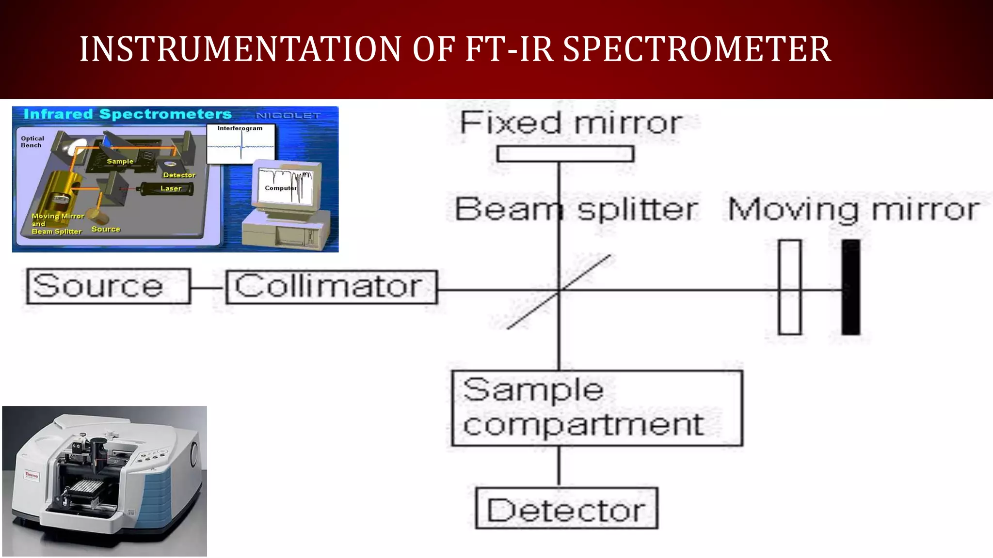
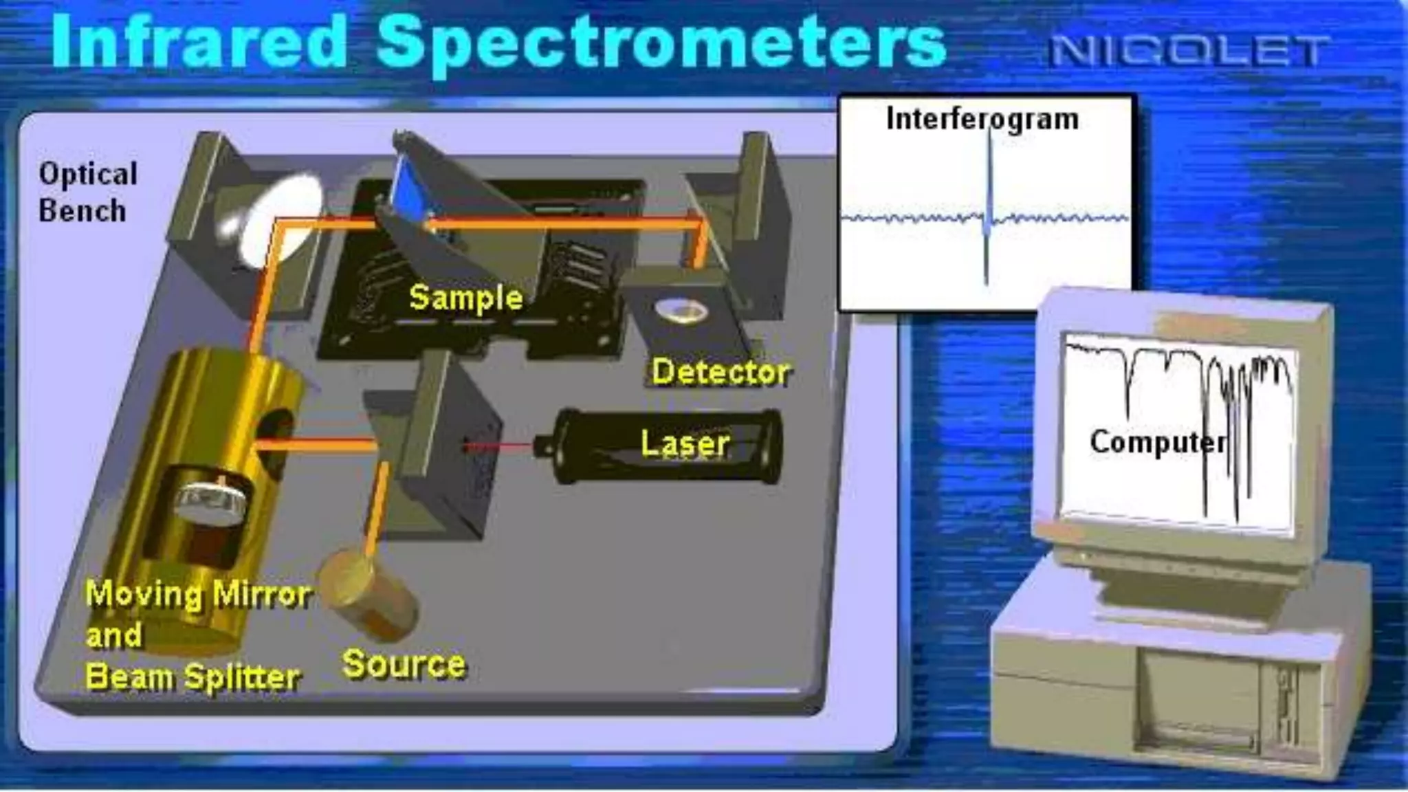
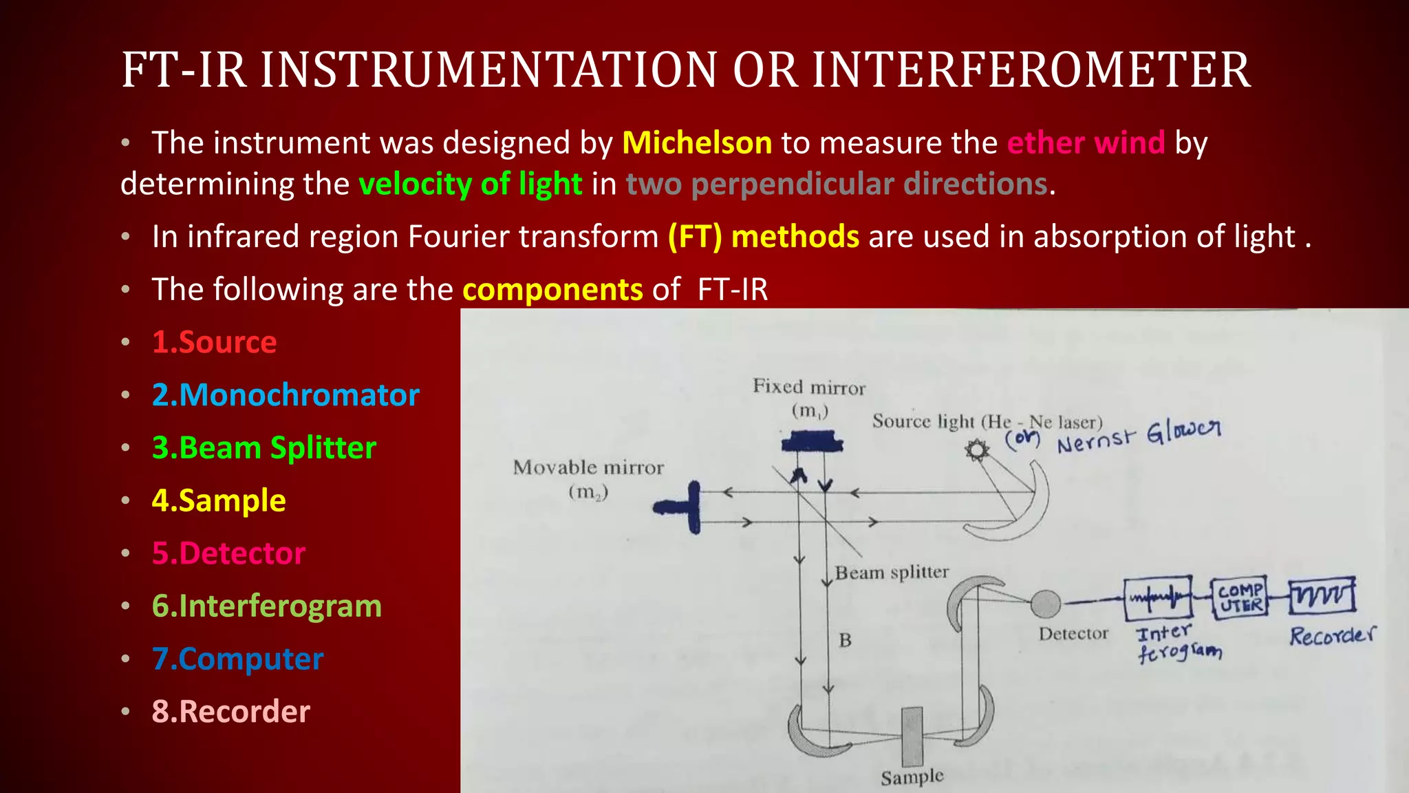
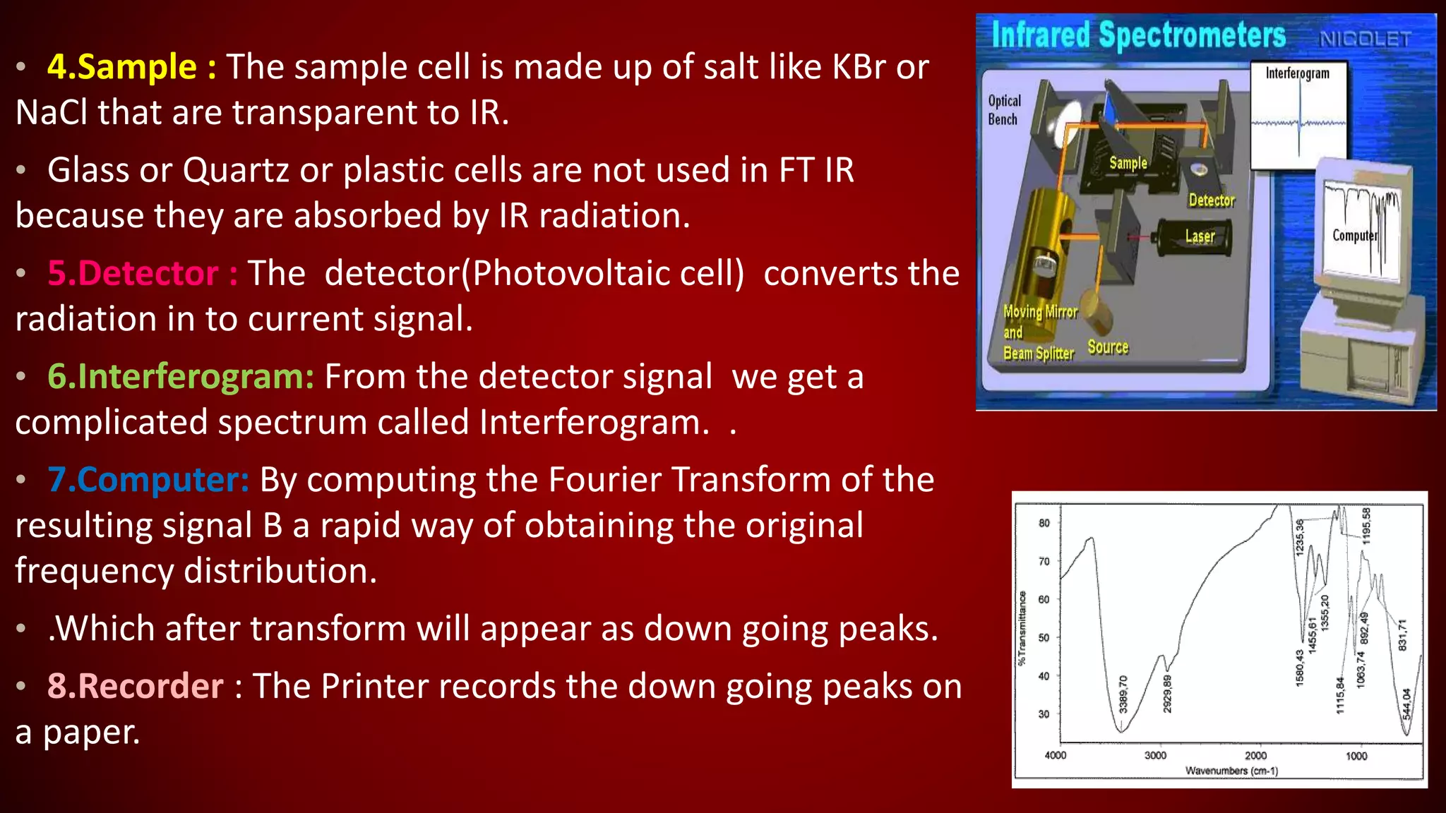
Achyuth’s
Chemistry Bees
The Online
Chemistry
Classes
By
G . Achyuth kumar M.Sc., B.Ed.(M.Phil.)
FT-IR INSTRUMENTATION
IR SPECTROSCOPY
IN
SPECTROSCOPIC TECHNIQUES
FT-I.R INSTRUMENTATION CONTENTS
• INTODUCTION
• PRINCIPLE
• CONSTRUCTION
• WORKING
• APPLICATIONS
INTRODUCTION & PRINCIPLE
• FT-IR full form is Fourier Transform-Infra Red spectroscopy.
• Fourier Transform IR Spectroscopy is employed for measurement of
vibration rotation transitions of diatomic molecules usually in gaseous
phase.
Principle:
• Based on the interferometry and interferogram will be obtained ,
which is a complex signal occurs in wave like pattern.
• Interferogram signal is plotted b/w intensity vs time.
• Mathematical calculation by Fourier Transform.
• FT-IR spectrum is generated by the plot b/w Intensity vs Frequency.
INSTRUMENTATION OF FT-IR SPECTROMETER
FT-IR INSTRUMENTATION OR INTERFEROMETER
• The instrument was designed by Michelson to measure the ether wind by
determining the velocity of light in two perpendicular directions.
• In infrared region Fourier transform (FT) methods are used in absorption of light .
• The following are the components of FT-IR
• 1.Source
• 2.Monochromator
• 3.Beam Splitter
• 4.Sample
• 5.Detector
• 6.Interferogram
• 7.Computer
• 8.Recorder
• 1.Source:
• The source of light is a Nernst filament consisting of spindle of rare Earth oxides about 1 inch long
and 0.1 inch diameter.
• In FT-IR a parallel beam of radiation is directed from the source to the interferometer.
• 2.Monochromator: Collimator is used as monochromator which gives single wavelength IR
radiation.
• 3.Beam Splitter : The parallel beam coming from light source of interferometer device that
separates a beam of light into two Ray beams consisting of beam splitter B andtwo Mirrors m1 and m2.
• The beam splitter is a plate of suitably transparent material (ex: KBR ) coated so as to reflect just
50% of radiation Falling On It.
• Thus half radiation goes to m2 one and half radiation goes to m 2 returns from both of these
Mirrors along the Same path and then be combined to single beam at a beam splitter half of the total
radiation is sent back to the source is well known that of monochromatic radiation is emitted by the
source the recombined Beam having B shows constructive or destructive interference depending on
the relative path length B to m1 and B to m2.
• Thus if the path lengths are identical or different by an integral wavelength constructive
interference gives a bright beam leaving B where half integral wave lengths of the beams cancelled at
B , as the mirror m2 moved smoothly toward or away from the B.
• 4.Sample : The sample cell is made up of salt like KBr or
NaCl that are transparent to IR.
• Glass or Quartz or plastic cells are not used in FT IR
because they are absorbed by IR radiation.
• 5.Detector : The detector(Photovoltaic cell) converts the
radiation in to current signal.
• 6.Interferogram: From the detector signal we get a
complicated spectrum called Interferogram. .
• 7.Computer: By computing the Fourier Transform of the
resulting signal B a rapid way of obtaining the original
frequency distribution.
• .Which after transform will appear as down going peaks.
• 8.Recorder : The Printer records the down going peaks on
a paper.
APPLICATIONS OF VIBRATIONAL SPECTROSCOPY/IR
SPECTROSCOPY
1. Rotational and vibrational (IR) Spectroscopy is uniquely precise tool
for the determination of molecular structure in gas phase molecules.
2. The technique has a key role in exploration of chemical
composition of the interstellar medium
3. This technique can be used for quantitative analysis.
4. It gives information about the specific Bonds, structures etc.
5. The vibrational bands will correspond to the characteristic
functional groups and bonds present in the chemical substance.
6. Bond positions and Bond intensities can be predicted by IR
spectroscopy.
By
G . Achyuth kumar M.Sc., B.Ed.(M.Phil.)

Ft ir instrumentation

  • 1.
  • 2.
  • 3.
    FT-I.R INSTRUMENTATION CONTENTS •INTODUCTION • PRINCIPLE • CONSTRUCTION • WORKING • APPLICATIONS
  • 4.
    INTRODUCTION & PRINCIPLE •FT-IR full form is Fourier Transform-Infra Red spectroscopy. • Fourier Transform IR Spectroscopy is employed for measurement of vibration rotation transitions of diatomic molecules usually in gaseous phase. Principle: • Based on the interferometry and interferogram will be obtained , which is a complex signal occurs in wave like pattern. • Interferogram signal is plotted b/w intensity vs time. • Mathematical calculation by Fourier Transform. • FT-IR spectrum is generated by the plot b/w Intensity vs Frequency.
  • 5.
  • 7.
    FT-IR INSTRUMENTATION ORINTERFEROMETER • The instrument was designed by Michelson to measure the ether wind by determining the velocity of light in two perpendicular directions. • In infrared region Fourier transform (FT) methods are used in absorption of light . • The following are the components of FT-IR • 1.Source • 2.Monochromator • 3.Beam Splitter • 4.Sample • 5.Detector • 6.Interferogram • 7.Computer • 8.Recorder
  • 8.
    • 1.Source: • Thesource of light is a Nernst filament consisting of spindle of rare Earth oxides about 1 inch long and 0.1 inch diameter. • In FT-IR a parallel beam of radiation is directed from the source to the interferometer. • 2.Monochromator: Collimator is used as monochromator which gives single wavelength IR radiation. • 3.Beam Splitter : The parallel beam coming from light source of interferometer device that separates a beam of light into two Ray beams consisting of beam splitter B andtwo Mirrors m1 and m2. • The beam splitter is a plate of suitably transparent material (ex: KBR ) coated so as to reflect just 50% of radiation Falling On It. • Thus half radiation goes to m2 one and half radiation goes to m 2 returns from both of these Mirrors along the Same path and then be combined to single beam at a beam splitter half of the total radiation is sent back to the source is well known that of monochromatic radiation is emitted by the source the recombined Beam having B shows constructive or destructive interference depending on the relative path length B to m1 and B to m2. • Thus if the path lengths are identical or different by an integral wavelength constructive interference gives a bright beam leaving B where half integral wave lengths of the beams cancelled at B , as the mirror m2 moved smoothly toward or away from the B.
  • 9.
    • 4.Sample :The sample cell is made up of salt like KBr or NaCl that are transparent to IR. • Glass or Quartz or plastic cells are not used in FT IR because they are absorbed by IR radiation. • 5.Detector : The detector(Photovoltaic cell) converts the radiation in to current signal. • 6.Interferogram: From the detector signal we get a complicated spectrum called Interferogram. . • 7.Computer: By computing the Fourier Transform of the resulting signal B a rapid way of obtaining the original frequency distribution. • .Which after transform will appear as down going peaks. • 8.Recorder : The Printer records the down going peaks on a paper.
  • 10.
    APPLICATIONS OF VIBRATIONALSPECTROSCOPY/IR SPECTROSCOPY 1. Rotational and vibrational (IR) Spectroscopy is uniquely precise tool for the determination of molecular structure in gas phase molecules. 2. The technique has a key role in exploration of chemical composition of the interstellar medium 3. This technique can be used for quantitative analysis. 4. It gives information about the specific Bonds, structures etc. 5. The vibrational bands will correspond to the characteristic functional groups and bonds present in the chemical substance. 6. Bond positions and Bond intensities can be predicted by IR spectroscopy.
  • 11.
    By G . Achyuthkumar M.Sc., B.Ed.(M.Phil.)