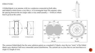
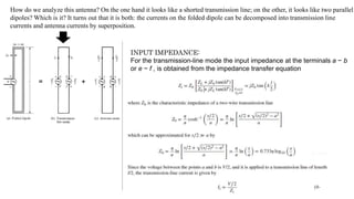
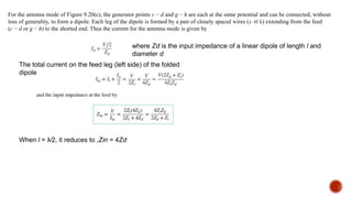
SlideShare a Scribd company logo
BY:
Why Folded Dipole?
To achieve good directional pattern characteristics and at the same time provide good matching
to practical coaxial lines with 50- or 75-ohm characteristic impedances, the length of a single wire
element is usually chosen to be λ∕4 ≤ l < λ. The most widely used dipole is that whose overall length
is l ≃ λ∕2, and which has an input impedance of Zin ≃ 73 + j42.5 and directivity of D0 ≃ 1.643. In
practice, there are other very common transmission lines whose characteristic impedance is much higher than 50 or 75
ohms. For example, a “twin-lead” transmission line (usually two parallel wires
separated by about 5/16 in. and embedded in a low-loss plastic material used for support and spacing)
is widely used for TV applications and has a characteristic impedance of about 300 ohms.
In order to provide good matching characteristics, variations of the single dipole element must be
Used, One such is the Folded Dipole.
it serves as a step-up impedance transformer (approximately by a factor of 4 when l = λ∕2) of the single-element impedance.
The folded dipole is a very popular wire antenna, for a number of reasons:
• Impedance properties
• Ease of construction;
• Structural rigidity ,
• Wider bandwidth than λ/2 dipole
STRUCTURE:
A folded dipole is an antenna, with two conductors connected on both sides,
and folded to which forms a very thin (s ≪ λ) rectangular loop This antenna, when
the spacing between the two larger sides is very small (usually s < 0.05λ) to which
feed is given at the center.
s
The common folded dipole has the same radiation pattern as a standard λ/2 dipole, since the two “arms” of the folded
dipole carry identical, half-wave sinusoidal current distributions. The currents are so close that we can treat them as a
single λ/2 length of wire.
How do we analyze this antenna? On the one hand it looks like a shorted transmission line; on the other, it looks like two parallel
dipoles? Which is it? It turns out that it is both: the currents on the folded dipole can be decomposed into transmission line
currents and antenna currents by superposition.
INPUT IMPEDANCE:
For the transmission-line mode the input impedance at the terminals a − b
or e − f , is obtained from the impedance transfer equation
For the antenna mode of Figure 9.20(c), the generator points c − d and g − h are each at the same potential and can be connected, without
loss of generality, to form a dipole. Each leg of the dipole is formed by a pair of closely spaced wires (s ≪ λ) extending from the feed
(c − d or g − h) to the shorted end. Thus the current for the antenna mode is given by
where Zd is the input impedance of a linear dipole of length l and
diameter d
The total current on the feed leg (left side) of the folded
dipole
When l = λ∕2, it reduces to ,Zin = 4Zd
Folded DIPOLE           ;           l     .pptx

More Related Content

Similar to Folded DIPOLE ; l .pptx

Reduced Dielectric Losses for Underground Cable Distribution Systems
Reduced Dielectric Losses for Underground Cable Distribution SystemsReduced Dielectric Losses for Underground Cable Distribution Systems
Reduced Dielectric Losses for Underground Cable Distribution Systems
IJAPEJOURNAL
 
BASIC CONCEPTS OF TRANSMISSION LINES & WAVEGUIDES ForC 18 DECE unit 1, SBTET
BASIC CONCEPTS OF TRANSMISSION LINES  &  WAVEGUIDES ForC 18 DECE unit 1, SBTETBASIC CONCEPTS OF TRANSMISSION LINES  &  WAVEGUIDES ForC 18 DECE unit 1, SBTET
BASIC CONCEPTS OF TRANSMISSION LINES & WAVEGUIDES ForC 18 DECE unit 1, SBTET
janakiravi
 
Ap unit 1
Ap unit 1Ap unit 1
Ap unit 1
vinutnaujwalag
 
power system 1 unit 2 ppt (2).pptx
power system 1 unit 2 ppt (2).pptxpower system 1 unit 2 ppt (2).pptx
power system 1 unit 2 ppt (2).pptx
monikavardia
 
Cp13.pptx
Cp13.pptxCp13.pptx
Cp13.pptx
DOAFCLF
 
A practical design of lumped, semi lumped & microwave cavity filters
A practical design of lumped, semi lumped & microwave cavity filtersA practical design of lumped, semi lumped & microwave cavity filters
A practical design of lumped, semi lumped & microwave cavity filters
Springer
 
power system 1 unit 2 ppt (2).pptx
power system 1 unit 2 ppt (2).pptxpower system 1 unit 2 ppt (2).pptx
power system 1 unit 2 ppt (2).pptx
monikavardia
 
Improved Blocked Impedance Model for Loudspeakers
Improved Blocked Impedance Model for LoudspeakersImproved Blocked Impedance Model for Loudspeakers
Improved Blocked Impedance Model for Loudspeakers
Andy Unruh
 
Application of LFAC { Hz} for electrical power transmission system: a compara...
Application of LFAC { Hz} for electrical power transmission system: a compara...Application of LFAC { Hz} for electrical power transmission system: a compara...
Application of LFAC { Hz} for electrical power transmission system: a compara...
TELKOMNIKA JOURNAL
 
Power capacity of transmission lines
Power capacity of transmission linesPower capacity of transmission lines
Power capacity of transmission lines
Alexander Decker
 
lect_antennaslect_antennaslect_antennasl
lect_antennaslect_antennaslect_antennasllect_antennaslect_antennaslect_antennasl
lect_antennaslect_antennaslect_antennasl
tnnny3090
 
Attenuation and surge impedance loading
Attenuation and surge impedance loadingAttenuation and surge impedance loading
Attenuation and surge impedance loading
Donalduo
 
Dipole antenna aerial tutorial
Dipole antenna  aerial tutorialDipole antenna  aerial tutorial
Dipole antenna aerial tutorial
Manoj Kumar Rai
 
TLW_Unit I material pdf.ppt
TLW_Unit I material pdf.pptTLW_Unit I material pdf.ppt
TLW_Unit I material pdf.ppt
KanmaniRajamanickam
 
Chapter 2 mukesh gurjar
Chapter 2 mukesh gurjarChapter 2 mukesh gurjar
Chapter 2 mukesh gurjar
Mukesh gurjar
 
Hvdc
HvdcHvdc
Transmission Line by YEASIN NEWAJ
Transmission Line by YEASIN NEWAJTransmission Line by YEASIN NEWAJ
Transmission Line by YEASIN NEWAJ
YeasinNewaj
 
wireless power transfer
wireless power transferwireless power transfer
wireless power transfer
Mimar Sinan Saraç
 
Chapter 2 transmission line parameters
Chapter 2  transmission line parametersChapter 2  transmission line parameters
Chapter 2 transmission line parameters
firaoltemesgen1
 
1.mid course
1.mid course1.mid course
1.mid course
UET Peshawar
 

Similar to Folded DIPOLE ; l .pptx (20)

Reduced Dielectric Losses for Underground Cable Distribution Systems
Reduced Dielectric Losses for Underground Cable Distribution SystemsReduced Dielectric Losses for Underground Cable Distribution Systems
Reduced Dielectric Losses for Underground Cable Distribution Systems
 
BASIC CONCEPTS OF TRANSMISSION LINES & WAVEGUIDES ForC 18 DECE unit 1, SBTET
BASIC CONCEPTS OF TRANSMISSION LINES  &  WAVEGUIDES ForC 18 DECE unit 1, SBTETBASIC CONCEPTS OF TRANSMISSION LINES  &  WAVEGUIDES ForC 18 DECE unit 1, SBTET
BASIC CONCEPTS OF TRANSMISSION LINES & WAVEGUIDES ForC 18 DECE unit 1, SBTET
 
Ap unit 1
Ap unit 1Ap unit 1
Ap unit 1
 
power system 1 unit 2 ppt (2).pptx
power system 1 unit 2 ppt (2).pptxpower system 1 unit 2 ppt (2).pptx
power system 1 unit 2 ppt (2).pptx
 
Cp13.pptx
Cp13.pptxCp13.pptx
Cp13.pptx
 
A practical design of lumped, semi lumped & microwave cavity filters
A practical design of lumped, semi lumped & microwave cavity filtersA practical design of lumped, semi lumped & microwave cavity filters
A practical design of lumped, semi lumped & microwave cavity filters
 
power system 1 unit 2 ppt (2).pptx
power system 1 unit 2 ppt (2).pptxpower system 1 unit 2 ppt (2).pptx
power system 1 unit 2 ppt (2).pptx
 
Improved Blocked Impedance Model for Loudspeakers
Improved Blocked Impedance Model for LoudspeakersImproved Blocked Impedance Model for Loudspeakers
Improved Blocked Impedance Model for Loudspeakers
 
Application of LFAC { Hz} for electrical power transmission system: a compara...
Application of LFAC { Hz} for electrical power transmission system: a compara...Application of LFAC { Hz} for electrical power transmission system: a compara...
Application of LFAC { Hz} for electrical power transmission system: a compara...
 
Power capacity of transmission lines
Power capacity of transmission linesPower capacity of transmission lines
Power capacity of transmission lines
 
lect_antennaslect_antennaslect_antennasl
lect_antennaslect_antennaslect_antennasllect_antennaslect_antennaslect_antennasl
lect_antennaslect_antennaslect_antennasl
 
Attenuation and surge impedance loading
Attenuation and surge impedance loadingAttenuation and surge impedance loading
Attenuation and surge impedance loading
 
Dipole antenna aerial tutorial
Dipole antenna  aerial tutorialDipole antenna  aerial tutorial
Dipole antenna aerial tutorial
 
TLW_Unit I material pdf.ppt
TLW_Unit I material pdf.pptTLW_Unit I material pdf.ppt
TLW_Unit I material pdf.ppt
 
Chapter 2 mukesh gurjar
Chapter 2 mukesh gurjarChapter 2 mukesh gurjar
Chapter 2 mukesh gurjar
 
Hvdc
HvdcHvdc
Hvdc
 
Transmission Line by YEASIN NEWAJ
Transmission Line by YEASIN NEWAJTransmission Line by YEASIN NEWAJ
Transmission Line by YEASIN NEWAJ
 
wireless power transfer
wireless power transferwireless power transfer
wireless power transfer
 
Chapter 2 transmission line parameters
Chapter 2  transmission line parametersChapter 2  transmission line parameters
Chapter 2 transmission line parameters
 
1.mid course
1.mid course1.mid course
1.mid course
 

Recently uploaded

Electric vehicle and photovoltaic advanced roles in enhancing the financial p...
Electric vehicle and photovoltaic advanced roles in enhancing the financial p...Electric vehicle and photovoltaic advanced roles in enhancing the financial p...
Electric vehicle and photovoltaic advanced roles in enhancing the financial p...
IJECEIAES
 
Digital Twins Computer Networking Paper Presentation.pptx
Digital Twins Computer Networking Paper Presentation.pptxDigital Twins Computer Networking Paper Presentation.pptx
Digital Twins Computer Networking Paper Presentation.pptx
aryanpankaj78
 
Software Engineering and Project Management - Software Testing + Agile Method...
Software Engineering and Project Management - Software Testing + Agile Method...Software Engineering and Project Management - Software Testing + Agile Method...
Software Engineering and Project Management - Software Testing + Agile Method...
Prakhyath Rai
 
132/33KV substation case study Presentation
132/33KV substation case study Presentation132/33KV substation case study Presentation
132/33KV substation case study Presentation
kandramariana6
 
Design and optimization of ion propulsion drone
Design and optimization of ion propulsion droneDesign and optimization of ion propulsion drone
Design and optimization of ion propulsion drone
bjmsejournal
 
VARIABLE FREQUENCY DRIVE. VFDs are widely used in industrial applications for...
VARIABLE FREQUENCY DRIVE. VFDs are widely used in industrial applications for...VARIABLE FREQUENCY DRIVE. VFDs are widely used in industrial applications for...
VARIABLE FREQUENCY DRIVE. VFDs are widely used in industrial applications for...
PIMR BHOPAL
 
Mechanical Engineering on AAI Summer Training Report-003.pdf
Mechanical Engineering on AAI Summer Training Report-003.pdfMechanical Engineering on AAI Summer Training Report-003.pdf
Mechanical Engineering on AAI Summer Training Report-003.pdf
21UME003TUSHARDEB
 
学校原版美国波士顿大学毕业证学历学位证书原版一模一样
学校原版美国波士顿大学毕业证学历学位证书原版一模一样学校原版美国波士顿大学毕业证学历学位证书原版一模一样
学校原版美国波士顿大学毕业证学历学位证书原版一模一样
171ticu
 
Data Driven Maintenance | UReason Webinar
Data Driven Maintenance | UReason WebinarData Driven Maintenance | UReason Webinar
Data Driven Maintenance | UReason Webinar
UReason
 
Comparative analysis between traditional aquaponics and reconstructed aquapon...
Comparative analysis between traditional aquaponics and reconstructed aquapon...Comparative analysis between traditional aquaponics and reconstructed aquapon...
Comparative analysis between traditional aquaponics and reconstructed aquapon...
bijceesjournal
 
Advanced control scheme of doubly fed induction generator for wind turbine us...
Advanced control scheme of doubly fed induction generator for wind turbine us...Advanced control scheme of doubly fed induction generator for wind turbine us...
Advanced control scheme of doubly fed induction generator for wind turbine us...
IJECEIAES
 
2008 BUILDING CONSTRUCTION Illustrated - Ching Chapter 02 The Building.pdf
2008 BUILDING CONSTRUCTION Illustrated - Ching Chapter 02 The Building.pdf2008 BUILDING CONSTRUCTION Illustrated - Ching Chapter 02 The Building.pdf
2008 BUILDING CONSTRUCTION Illustrated - Ching Chapter 02 The Building.pdf
Yasser Mahgoub
 
Computational Engineering IITH Presentation
Computational Engineering IITH PresentationComputational Engineering IITH Presentation
Computational Engineering IITH Presentation
co23btech11018
 
AI for Legal Research with applications, tools
AI for Legal Research with applications, toolsAI for Legal Research with applications, tools
AI for Legal Research with applications, tools
mahaffeycheryld
 
一比一原版(爱大毕业证书)爱荷华大学毕业证如何办理
一比一原版(爱大毕业证书)爱荷华大学毕业证如何办理一比一原版(爱大毕业证书)爱荷华大学毕业证如何办理
一比一原版(爱大毕业证书)爱荷华大学毕业证如何办理
nedcocy
 
1FIDIC-CONSTRUCTION-CONTRACT-2ND-ED-2017-RED-BOOK.pdf
1FIDIC-CONSTRUCTION-CONTRACT-2ND-ED-2017-RED-BOOK.pdf1FIDIC-CONSTRUCTION-CONTRACT-2ND-ED-2017-RED-BOOK.pdf
1FIDIC-CONSTRUCTION-CONTRACT-2ND-ED-2017-RED-BOOK.pdf
MadhavJungKarki
 
TIME TABLE MANAGEMENT SYSTEM testing.pptx
TIME TABLE MANAGEMENT SYSTEM testing.pptxTIME TABLE MANAGEMENT SYSTEM testing.pptx
TIME TABLE MANAGEMENT SYSTEM testing.pptx
CVCSOfficial
 
2008 BUILDING CONSTRUCTION Illustrated - Ching Chapter 08 Doors and Windows.pdf
2008 BUILDING CONSTRUCTION Illustrated - Ching Chapter 08 Doors and Windows.pdf2008 BUILDING CONSTRUCTION Illustrated - Ching Chapter 08 Doors and Windows.pdf
2008 BUILDING CONSTRUCTION Illustrated - Ching Chapter 08 Doors and Windows.pdf
Yasser Mahgoub
 
morris_worm_intro_and_source_code_analysis_.pdf
morris_worm_intro_and_source_code_analysis_.pdfmorris_worm_intro_and_source_code_analysis_.pdf
morris_worm_intro_and_source_code_analysis_.pdf
ycwu0509
 
Use PyCharm for remote debugging of WSL on a Windo cf5c162d672e4e58b4dde5d797...
Use PyCharm for remote debugging of WSL on a Windo cf5c162d672e4e58b4dde5d797...Use PyCharm for remote debugging of WSL on a Windo cf5c162d672e4e58b4dde5d797...
Use PyCharm for remote debugging of WSL on a Windo cf5c162d672e4e58b4dde5d797...
shadow0702a
 

Recently uploaded (20)

Electric vehicle and photovoltaic advanced roles in enhancing the financial p...
Electric vehicle and photovoltaic advanced roles in enhancing the financial p...Electric vehicle and photovoltaic advanced roles in enhancing the financial p...
Electric vehicle and photovoltaic advanced roles in enhancing the financial p...
 
Digital Twins Computer Networking Paper Presentation.pptx
Digital Twins Computer Networking Paper Presentation.pptxDigital Twins Computer Networking Paper Presentation.pptx
Digital Twins Computer Networking Paper Presentation.pptx
 
Software Engineering and Project Management - Software Testing + Agile Method...
Software Engineering and Project Management - Software Testing + Agile Method...Software Engineering and Project Management - Software Testing + Agile Method...
Software Engineering and Project Management - Software Testing + Agile Method...
 
132/33KV substation case study Presentation
132/33KV substation case study Presentation132/33KV substation case study Presentation
132/33KV substation case study Presentation
 
Design and optimization of ion propulsion drone
Design and optimization of ion propulsion droneDesign and optimization of ion propulsion drone
Design and optimization of ion propulsion drone
 
VARIABLE FREQUENCY DRIVE. VFDs are widely used in industrial applications for...
VARIABLE FREQUENCY DRIVE. VFDs are widely used in industrial applications for...VARIABLE FREQUENCY DRIVE. VFDs are widely used in industrial applications for...
VARIABLE FREQUENCY DRIVE. VFDs are widely used in industrial applications for...
 
Mechanical Engineering on AAI Summer Training Report-003.pdf
Mechanical Engineering on AAI Summer Training Report-003.pdfMechanical Engineering on AAI Summer Training Report-003.pdf
Mechanical Engineering on AAI Summer Training Report-003.pdf
 
学校原版美国波士顿大学毕业证学历学位证书原版一模一样
学校原版美国波士顿大学毕业证学历学位证书原版一模一样学校原版美国波士顿大学毕业证学历学位证书原版一模一样
学校原版美国波士顿大学毕业证学历学位证书原版一模一样
 
Data Driven Maintenance | UReason Webinar
Data Driven Maintenance | UReason WebinarData Driven Maintenance | UReason Webinar
Data Driven Maintenance | UReason Webinar
 
Comparative analysis between traditional aquaponics and reconstructed aquapon...
Comparative analysis between traditional aquaponics and reconstructed aquapon...Comparative analysis between traditional aquaponics and reconstructed aquapon...
Comparative analysis between traditional aquaponics and reconstructed aquapon...
 
Advanced control scheme of doubly fed induction generator for wind turbine us...
Advanced control scheme of doubly fed induction generator for wind turbine us...Advanced control scheme of doubly fed induction generator for wind turbine us...
Advanced control scheme of doubly fed induction generator for wind turbine us...
 
2008 BUILDING CONSTRUCTION Illustrated - Ching Chapter 02 The Building.pdf
2008 BUILDING CONSTRUCTION Illustrated - Ching Chapter 02 The Building.pdf2008 BUILDING CONSTRUCTION Illustrated - Ching Chapter 02 The Building.pdf
2008 BUILDING CONSTRUCTION Illustrated - Ching Chapter 02 The Building.pdf
 
Computational Engineering IITH Presentation
Computational Engineering IITH PresentationComputational Engineering IITH Presentation
Computational Engineering IITH Presentation
 
AI for Legal Research with applications, tools
AI for Legal Research with applications, toolsAI for Legal Research with applications, tools
AI for Legal Research with applications, tools
 
一比一原版(爱大毕业证书)爱荷华大学毕业证如何办理
一比一原版(爱大毕业证书)爱荷华大学毕业证如何办理一比一原版(爱大毕业证书)爱荷华大学毕业证如何办理
一比一原版(爱大毕业证书)爱荷华大学毕业证如何办理
 
1FIDIC-CONSTRUCTION-CONTRACT-2ND-ED-2017-RED-BOOK.pdf
1FIDIC-CONSTRUCTION-CONTRACT-2ND-ED-2017-RED-BOOK.pdf1FIDIC-CONSTRUCTION-CONTRACT-2ND-ED-2017-RED-BOOK.pdf
1FIDIC-CONSTRUCTION-CONTRACT-2ND-ED-2017-RED-BOOK.pdf
 
TIME TABLE MANAGEMENT SYSTEM testing.pptx
TIME TABLE MANAGEMENT SYSTEM testing.pptxTIME TABLE MANAGEMENT SYSTEM testing.pptx
TIME TABLE MANAGEMENT SYSTEM testing.pptx
 
2008 BUILDING CONSTRUCTION Illustrated - Ching Chapter 08 Doors and Windows.pdf
2008 BUILDING CONSTRUCTION Illustrated - Ching Chapter 08 Doors and Windows.pdf2008 BUILDING CONSTRUCTION Illustrated - Ching Chapter 08 Doors and Windows.pdf
2008 BUILDING CONSTRUCTION Illustrated - Ching Chapter 08 Doors and Windows.pdf
 
morris_worm_intro_and_source_code_analysis_.pdf
morris_worm_intro_and_source_code_analysis_.pdfmorris_worm_intro_and_source_code_analysis_.pdf
morris_worm_intro_and_source_code_analysis_.pdf
 
Use PyCharm for remote debugging of WSL on a Windo cf5c162d672e4e58b4dde5d797...
Use PyCharm for remote debugging of WSL on a Windo cf5c162d672e4e58b4dde5d797...Use PyCharm for remote debugging of WSL on a Windo cf5c162d672e4e58b4dde5d797...
Use PyCharm for remote debugging of WSL on a Windo cf5c162d672e4e58b4dde5d797...
 

Folded DIPOLE ; l .pptx

  • 1. BY:
  • 2. Why Folded Dipole? To achieve good directional pattern characteristics and at the same time provide good matching to practical coaxial lines with 50- or 75-ohm characteristic impedances, the length of a single wire element is usually chosen to be λ∕4 ≤ l < λ. The most widely used dipole is that whose overall length is l ≃ λ∕2, and which has an input impedance of Zin ≃ 73 + j42.5 and directivity of D0 ≃ 1.643. In practice, there are other very common transmission lines whose characteristic impedance is much higher than 50 or 75 ohms. For example, a “twin-lead” transmission line (usually two parallel wires separated by about 5/16 in. and embedded in a low-loss plastic material used for support and spacing) is widely used for TV applications and has a characteristic impedance of about 300 ohms. In order to provide good matching characteristics, variations of the single dipole element must be Used, One such is the Folded Dipole. it serves as a step-up impedance transformer (approximately by a factor of 4 when l = λ∕2) of the single-element impedance. The folded dipole is a very popular wire antenna, for a number of reasons: • Impedance properties • Ease of construction; • Structural rigidity , • Wider bandwidth than λ/2 dipole
  • 3. STRUCTURE: A folded dipole is an antenna, with two conductors connected on both sides, and folded to which forms a very thin (s ≪ λ) rectangular loop This antenna, when the spacing between the two larger sides is very small (usually s < 0.05λ) to which feed is given at the center. s The common folded dipole has the same radiation pattern as a standard λ/2 dipole, since the two “arms” of the folded dipole carry identical, half-wave sinusoidal current distributions. The currents are so close that we can treat them as a single λ/2 length of wire.
  • 4. How do we analyze this antenna? On the one hand it looks like a shorted transmission line; on the other, it looks like two parallel dipoles? Which is it? It turns out that it is both: the currents on the folded dipole can be decomposed into transmission line currents and antenna currents by superposition. INPUT IMPEDANCE: For the transmission-line mode the input impedance at the terminals a − b or e − f , is obtained from the impedance transfer equation
  • 5. For the antenna mode of Figure 9.20(c), the generator points c − d and g − h are each at the same potential and can be connected, without loss of generality, to form a dipole. Each leg of the dipole is formed by a pair of closely spaced wires (s ≪ λ) extending from the feed (c − d or g − h) to the shorted end. Thus the current for the antenna mode is given by where Zd is the input impedance of a linear dipole of length l and diameter d The total current on the feed leg (left side) of the folded dipole When l = λ∕2, it reduces to ,Zin = 4Zd