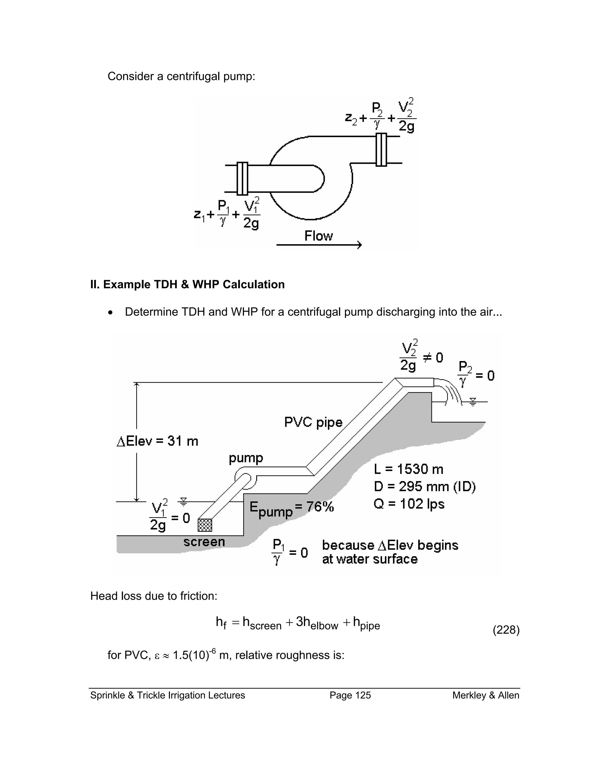
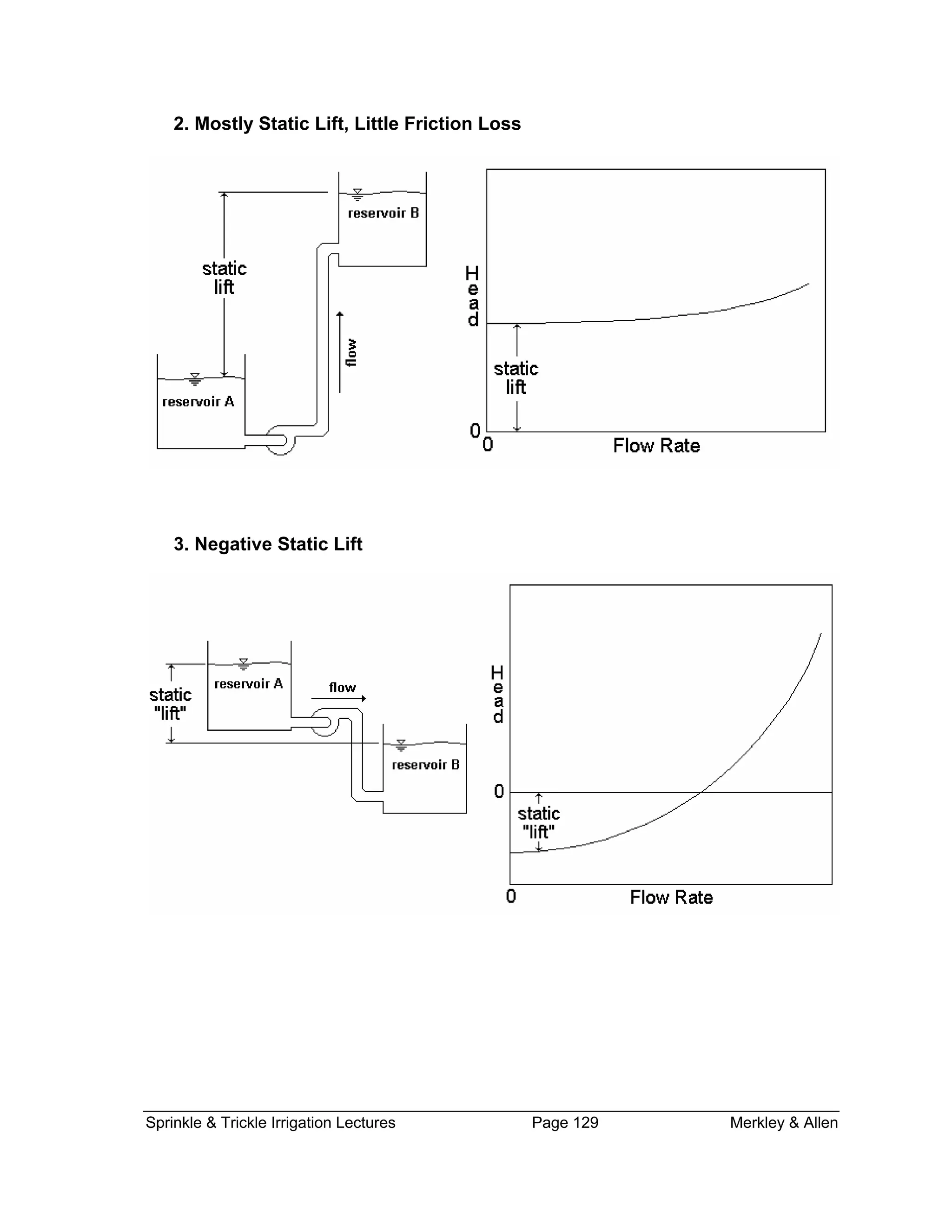
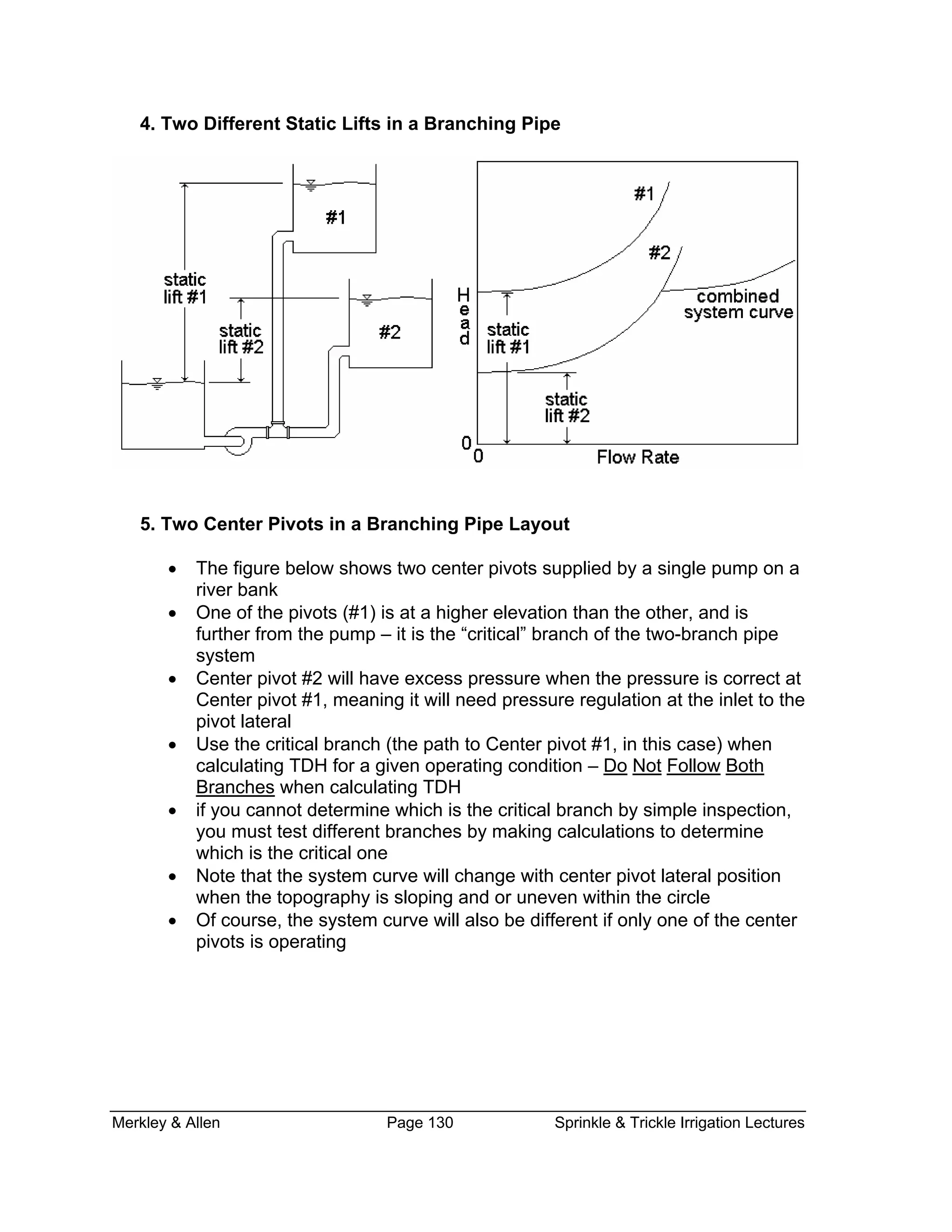
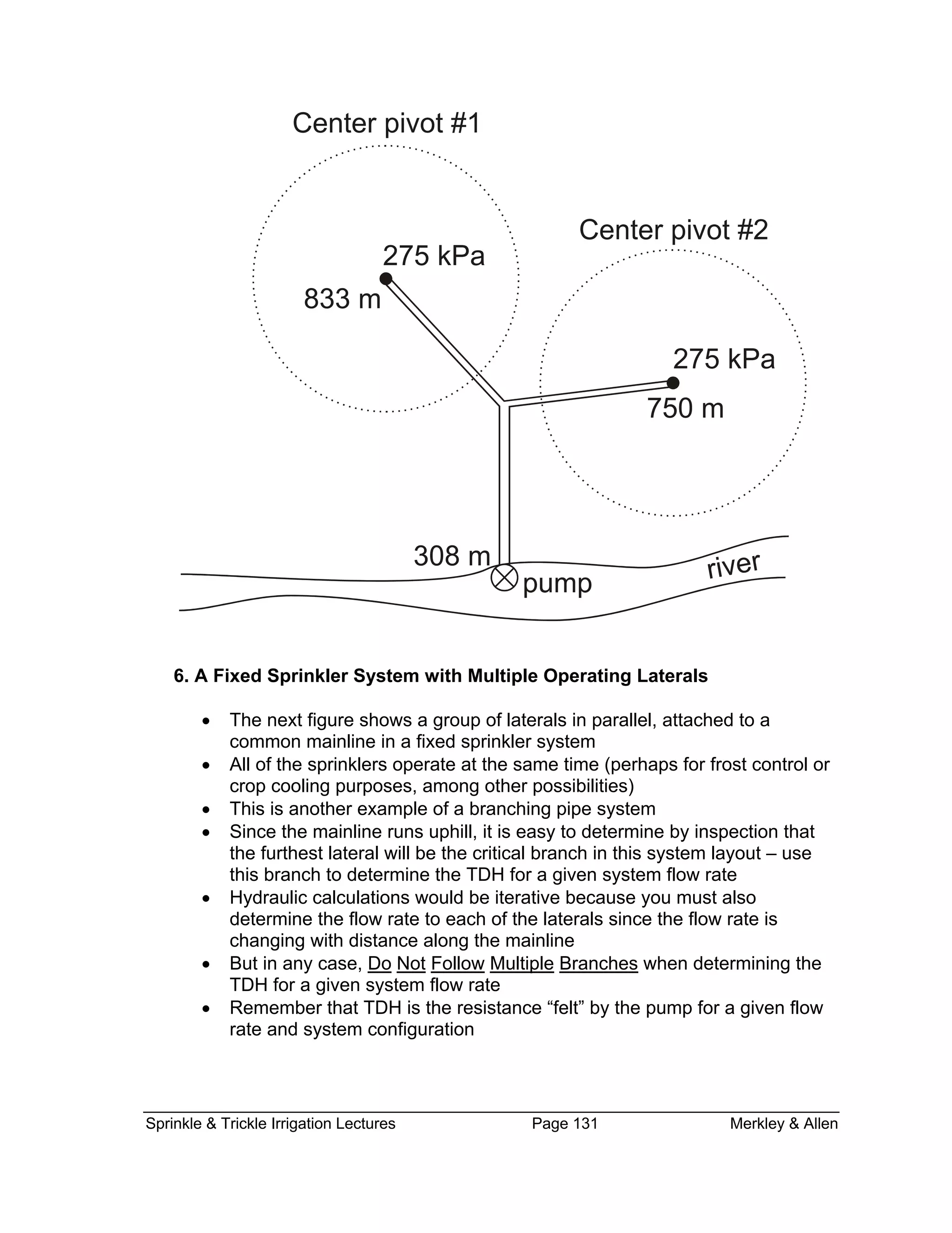
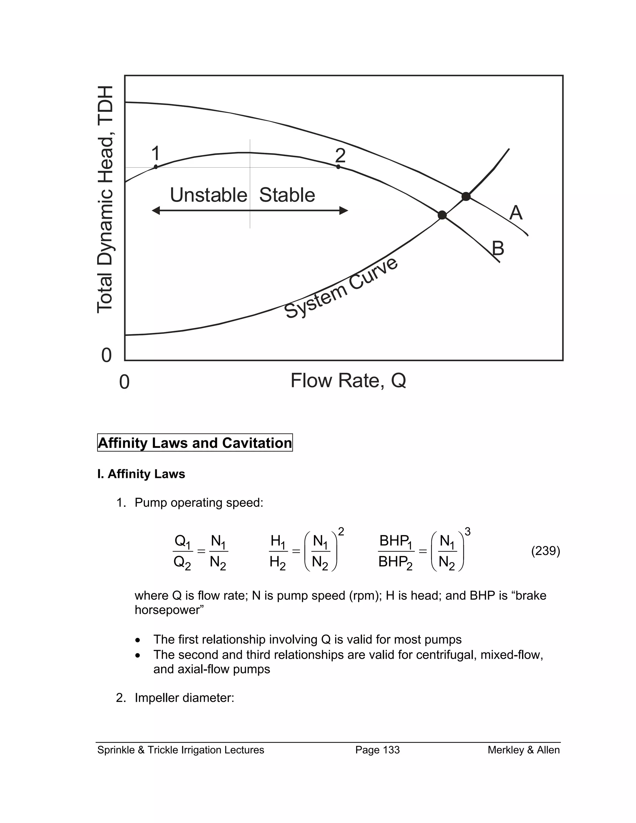
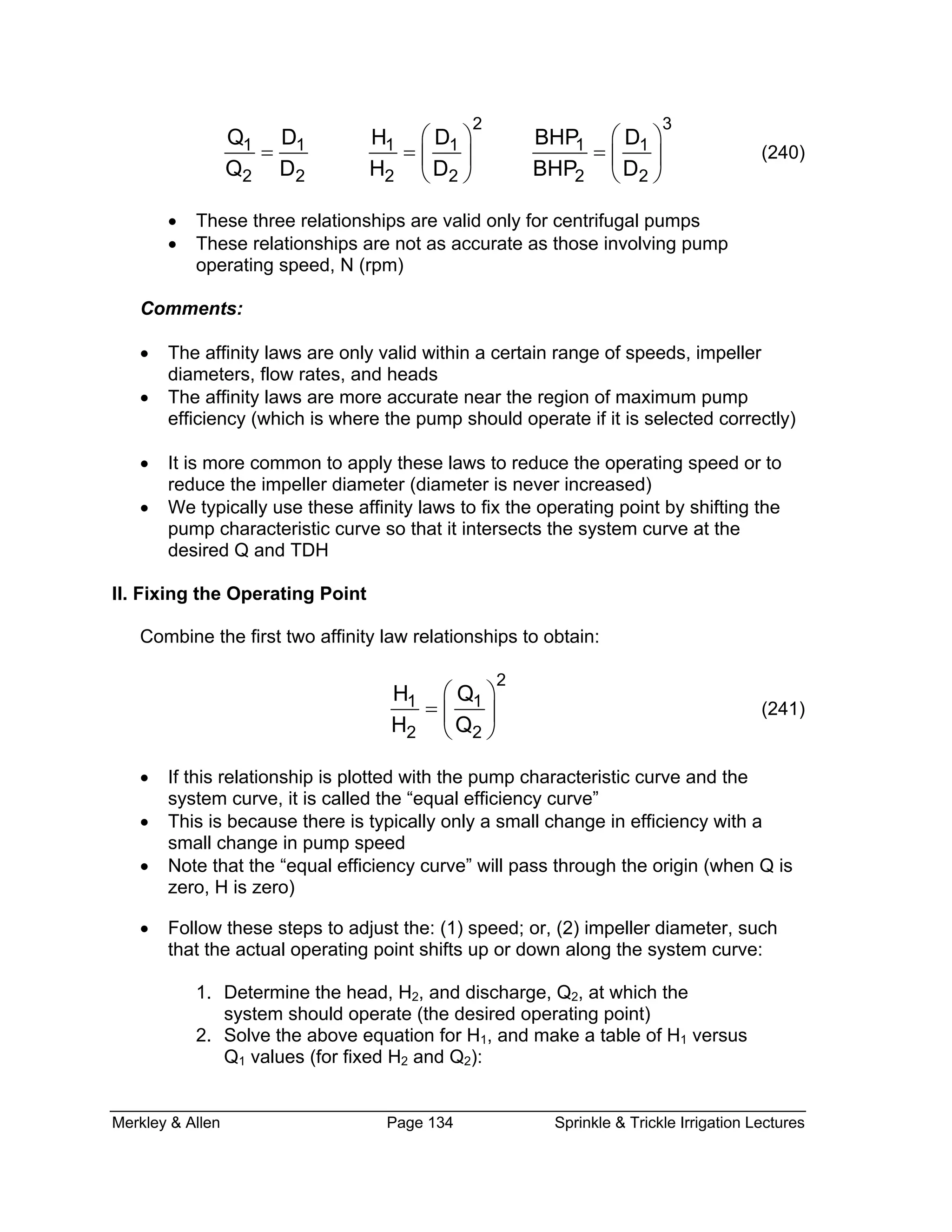
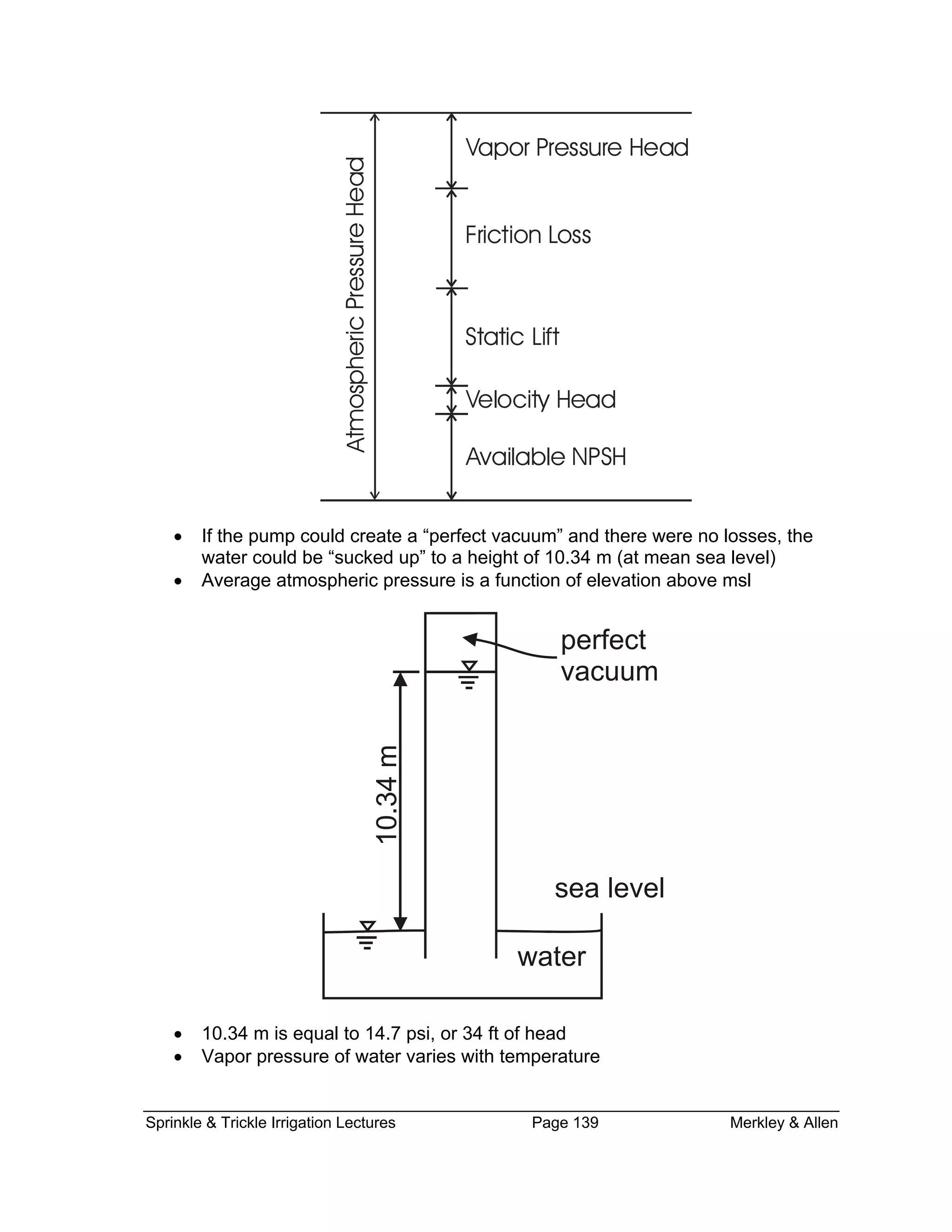
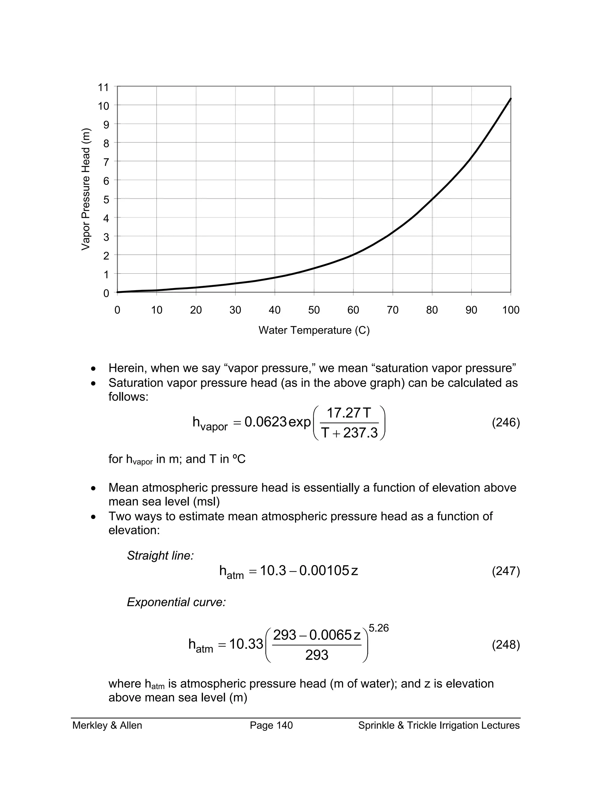
This document provides information on pump efficiency, power requirements, and system curves for sprinkler irrigation systems. It defines key terms like total dynamic head (TDH), water horsepower (WHP), and brake horsepower (BHP). An example calculation is shown to determine the TDH, WHP, and BHP required for a centrifugal pump discharging into air. Different types of system curves are described for scenarios involving static lift, friction loss, and multiple laterals or center pivots. Affinity laws relating flow, head, speed, and power are also covered, along with using these laws to adjust a pump's operating point to match a system curve.
The document provides an introduction to pump analysis. It discusses that the purpose of a pump is to increase the mechanical energy in a fluid by transporting it from a lower elevation to a higher elevation. It then covers key pumping concepts like capacity, head, efficiency, and power input. Specific types of pumps are defined, including centrifugal pumps which are most commonly used for wastewater applications. Methods for analyzing pump performance including head-capacity curves and affinity laws are also introduced.
This document discusses pump selection and applications. It begins by outlining the chapter, which covers introductory concepts in pump selection, parameters to consider, types of pumps including positive displacement and kinetic pumps, and performance data for centrifugal pumps. The affinity laws relating speed, impeller diameter, capacity, head, and power for centrifugal pumps are also described. The chapter provides examples of pump performance curves and works through an example problem applying the affinity laws.
This document provides an overview of centrifugal pumps. It defines a pump and discusses the main components and classifications of centrifugal pumps. The key components of a centrifugal pump are the impeller, casing, suction pipe, and delivery pipe. Centrifugal pumps are classified based on impeller design and casing shape. The document also covers topics such as work done by the centrifugal pump, head of a pump, losses and efficiencies, and minimum speed for starting a centrifugal pump. Several example problems are provided to calculate values like inlet vane angle, work done, and minimum starting speed.
A pump is a mechanical device that transfers rotational energy to liquid to move it from one place to another. There are two main types of pumps: dynamic and positive displacement. A reciprocating pump is a type of positive displacement pump that uses a piston or plunger to trap and move liquid. A rotary pump also positively displaces liquid but does so continuously rather than reciprocating. A centrifugal pump is a type of dynamic pump that uses a rotating impeller to accelerate liquid and convert kinetic energy to pressure energy to move the liquid.
This document discusses different types of pumps, including their classifications, characteristics, applications, and performance. It describes hydrodynamic/non-positive displacement pumps, which use flow to transfer fluid at relatively low pressure and are generally used for low pressure, high volume applications. It also describes hydrostatic/positive displacement pumps, which have close-fitting components and can create high pressures, making them self-priming. Specific positive displacement pump types like gear, vane, piston and centrifugal pumps are examined in terms of their applications and operating principles. Pump efficiencies including volumetric, mechanical and overall efficiency are also covered.
Pumps are mechanical devices that use external power to transfer fluids from one point to another. There are two main types of pumps: positive displacement pumps and rotodynamic pumps. Positive displacement pumps include reciprocating pumps, rotary lobe pumps, progressing cavity pumps, piston/plunger pumps, dosing pumps, and vacuum pumps. Rotodynamic pumps include centrifugal pumps. Each pump type has different characteristics that make it suitable for various fluid transfer applications.
1. The document discusses various topics related to hydraulic turbines including their classification, selection, design principles of Pelton, Francis and Kaplan turbines, draft tubes, surge tanks, governing, unit quantities, characteristic curves, similitude analysis and cavitation.
2. Hydraulic turbines are classified based on the type of energy at the inlet, direction of flow through the runner, head at the inlet, and specific speed. Pelton wheels are impulse turbines suitable for high heads while Francis and Kaplan turbines are reaction turbines for lower heads.
3. The design of each turbine type involves guidelines related to jet ratio, speed ratio, velocities, discharge, power and efficiency calculations. Characteristic curves show the performance of a
The document discusses multi-stage centrifugal pumps. It explains that a multi-stage centrifugal pump has two or more impellers to produce a high head. In a series connection, the total head developed is equal to the number of impellers multiplied by the head developed by each impeller. In a parallel connection, multi-stage pumps are arranged in parallel to discharge a large quantity of liquid, with the total discharge equal to the number of pumps multiplied by the discharge from each pump. Some applications of multi-stage centrifugal pumps include pumping water in high-rise buildings, industrial wash down facilities, fire hydrant systems, boiler feed systems, and irrigation.
the presentation includes basic ideas about water pumps, various terminology generally used for the pumps, classification of pumps and ideas about the types its construction and working
Watch Video of this presentation on Link: https://youtu.be/g8eJsznmsaY
For notes/articles, Visit my blog (link is given below).
For Video, Visit our YouTube Channel (link is given below).
Any Suggestions/doubts/reactions, please leave in the comment box.
Follow Us on
YouTube: https://www.youtube.com/channel/UCVPftVoKZoIxVH_gh09bMkw/
Blog: https://e-gyaankosh.blogspot.com/
Facebook: https://www.facebook.com/egyaankosh/
This document discusses various types of pumps used to move water from lower to higher points. It describes centrifugal pumps, which use centrifugal force to move water radially outward, and positive displacement pumps like screw and reciprocating pumps. Key parts of centrifugal pumps are identified, including the impeller, casing, suction pipe, and delivery pipe. Concepts discussed include total dynamic head, pump efficiency, cavitation, net positive suction head, and the process of selecting a pump by matching its characteristic curve to the system curve.
This document provides an overview of the Pelton turbine. It describes the Pelton turbine as an impulse type water turbine invented by Lester Allan Pelton in the 1870s. The key parts of a Pelton turbine discussed include the penstock, runner, casing, spear rod, deflector, nozzle, and brake nozzle. It also briefly discusses the specific speed of turbines and notes that China produces the most hydroelectric power worldwide.
Basics Fundamentals and working Principle of Centrifugal Pump.SHASHI BHUSHAN
Basics Fundamentals and working Principle of Centrifugal Pump. Centrifugal pumps are the rotodynamic machines that convert mechanical energy of shaft into kinetic and pressure energy of Fluid which may be used to raise the level of fluid. A centrifugal pump is named so, because the energy added by the impeller to the fluid is largely due to centrifugal effects.
The document discusses considerations for selecting a pumping system, including fluid characteristics, system requirements, pump types, drive selection, and standby requirements. Key factors in pump selection are fluid type, system head curve, potential modifications, operational mode, required margins, and space/layout constraints. Reciprocating pumps are used for small liquid chemical metering while centrifugal pumps are common for a wide range of head and capacity needs. Net positive suction head (NPSH) must also be considered to ensure proper pump operation and avoid cavitation.
The Francis turbine is an inward flow reaction turbine with radial discharge at the outlet. It is a mixed-flow turbine where water enters the runner radially and exits axially. Francis turbines are used in applications with medium head between 45-250 meters. They have medium specific speeds between 50-250 and a vertically oriented shaft. Francis turbines are widely used worldwide due to their high efficiencies between 80-94%. However, they also have high costs due to their complex design and cavitation can be an issue.
Pump Cavitation & Net Positive Suction HeadHasnaın Sheıkh
This document summarizes key concepts related to pump cavitation and net positive suction head (NPSH). It defines cavitation as the formation of vapor bubbles when local pressure inside a pump drops below the vapor pressure of the liquid. Repeated cavitation can damage impeller blades through pitting and erosion. NPSH is introduced to quantify the pressure required to avoid cavitation. NPSH available considers the inlet pressure accounting for piping losses, while NPSH required is provided by pump manufacturers as the minimum pressure needed. The document outlines how NPSH available and required values vary with flow rate and other variables like liquid temperature.
Centrifugal pumps in series and parallelphysics101
Centrifugal pumps work by using a rotating impeller to increase the velocity of a liquid and discharge it out of the pump housing. They have advantages like being simple, compact, and able to handle high rpm, but disadvantages like poor suction power and needing multiple stages to increase pressure. Proper installation requires a tight suction line, independently supported piping, minimal fittings, and protection against air intake to optimize performance. Pumps can be arranged in series to increase total head or in parallel to increase overall flow rate.
Pump, its types and applications presentationziaul islam
This document discusses different types of pumps. It begins by defining a pump as a machine that converts mechanical energy into fluid energy by moving fluid from a region of low pressure to one of high pressure. There are two main types of pumps: positive displacement pumps and rotodynamic pumps. Positive displacement pumps work by trapping a fixed amount of fluid and forcing it into the discharge pipe. Rotodynamic pumps use rotational kinetic energy to increase the fluid's hydrodynamic energy. The document then discusses various sub-types of positive displacement pumps like gear pumps, screw pumps, and reciprocating pumps. It also covers different rotodynamic pump types such as centrifugal pumps, axial pumps, mixed-flow pumps, and turbine pumps. The document
A turbine is a rotary mechanical device that extracts energy from a fast moving flow of water, steam, gas, air, or other fluid and converts it into useful work. Also a turbine is a turbo-machine with at least one moving part called a rotor assembly, which is a shaft or drum with blades attached. Moving fluid acts on the blades so that they move and impart rotational energy to the rotor. According to the fluid used:
• Water Turbine
• Steam Turbine
• Gas Turbine
• Wind Turbine
Although the same principles apply to all turbines, their specific designs differ sufficiently to merit separate descriptions.
Working Principle Water Turbine
• When the fluid strikes the blades of the turbine, the blades are displaced, which produces rotational energy.
• When the turbine shaft is directly coupled to an electric generator mechanical energy is converted into electrical energy.
• This electrical power is known as hydroelectric power.
In a hydraulic turbine, water is used as the source of energy. Water or hydraulic turbines convert kinetic and potential energies of the water into mechanical power. Water turbines are mostly found in dams to generate electric power from water kinetic energy.
Classification
Based on hydraulic action of water
Based on direction of flow
Based on head of water and quantity of flow
Based on specific speed
Based on disposition of turbine shaft
Based on name of originator (commonly used turbines)
The document provides information about pumps, including:
1) Pumps are mechanical devices that use rotation or reciprocation to move fluid from one place to another by converting energy into hydraulic energy.
2) The main purposes of pumps are to transfer fluid from low to high pressure areas, from low to high elevations, and from local to distant locations.
3) There are two main types of pumps - positive displacement pumps which move a fixed volume of fluid with each cycle, and centrifugal pumps which use centrifugal force to move fluid by spinning an impeller.
This document discusses pumps, including their function, principle of operation, types, selection criteria, and engineering design process. The main types of pumps covered are centrifugal pumps and positive displacement pumps. Key factors in pump selection include the nature of the fluid being pumped, system requirements, environmental conditions, and cost. Pump performance is characterized using curves showing head, flow rate, and efficiency. Proper pump sizing and installation are important to avoid issues like cavitation.
Search Results
Web results
Pump - Wikipediaen.wikipedia.org › wiki › Pump
A pump is a device that moves fluids (liquids or gases), or sometimes slurries, by mechanical action, typically converted from electrical energy into Hydraulic energy. Pumps can be classified into three major groups according to the method they use to move the fluid: direct lift, displacement, and gravity pumps.
Specific Speed of Turbine | Fluid MechanicsSatish Taji
Watch Video of this presentation on Link: https://youtu.be/I0fHo0z6EgA
For notes/articles, Visit my blog (link is given below).
For Video, Visit our YouTube Channel (link is given below).
Any Suggestions/doubts/reactions, please leave in the comment box.
Follow Us on
YouTube: https://www.youtube.com/channel/UCVPftVoKZoIxVH_gh09bMkw/
Blog: https://e-gyaankosh.blogspot.com/
Facebook: https://www.facebook.com/egyaankosh/
The document discusses centrifugal pumps and pumping systems. It defines the key components of pumping systems including pumps, prime movers, piping, valves and other fittings. It explains the characteristics of pumping systems such as head, static head, friction head and how total head is the sum of static and friction head. It then describes the different types of pumps, focusing on centrifugal pumps. It explains how centrifugal pumps work using impellers to accelerate fluid radially outward, converting kinetic to pressure energy. It also discusses impeller types, casings, performance curves and system curves.
This document discusses water pumps, including their definition, classification, components, and operation. It describes how pumps work to convert mechanical energy into hydraulic energy to move water from lower to higher points. Pumps are classified as either turbo-hydraulic (centrifugal or positive displacement). Centrifugal pumps are the most common and their components and operation are explained in detail. Key concepts discussed include pump efficiency, cavitation, net positive suction head (NPSH), and selecting the appropriate pump based on system characteristics.
Southern Methodist UniversityBobby B. Lyle School of Engineeri.docxwhitneyleman54422
This document discusses pump selection and piping systems for fluid flow. It provides definitions for different types of pumps (e.g. centrifugal, positive displacement) and describes how they are used for various applications. It also discusses concepts like pump curves, system curves and selecting a suitable pump for a given piping system. Finally, it covers topics like multiple pipe systems with pipes in series, parallel and branching configurations, and how to analyze flow through such complex pipe networks.
Based on the information provided:
- Gage pressure (vacuum) = -20 inches of Hg
- Convert to psi: -20 inches Hg x 0.4912 psi/inch Hg = -9.824 psi
- Atmospheric pressure = 14.7 psi
- Liquid level above pump centerline is not provided
To calculate NPSHA:
- Atmospheric pressure (psi) converted to head = 14.7 psi x 2.31 ft/psi = 34 ft
- Gage pressure (vacuum, psi) converted to head = -9.824 psi x 2.31 ft/psi = -22.7 ft
- Static head = Unknown (not provided)
This document provides an overview of fundamentals for water system design and pump selection. It covers topics such as hydronic system components, distribution piping system design, direct and reverse return systems, centrifugal pumps, pump performance curves, system curves, pump selection parameters, and pump arrangements. The document aims to guide designers on water system design limitations, pump types, how to read pump curves and select the proper pump based on factors like design flow, pressure requirements, and system characteristics.
Performance of a_centrifugal_pump_autosavedDickens Mimisa
The document summarizes an experimental analysis of a centrifugal pump performed by a student. Key findings include:
- The experiment investigated the relationship between head, discharge, input power, and efficiency of a centrifugal pump under different revolution speeds.
- Data was collected manually and analyzed to determine the pump's characteristic curve and efficiency at varying flow rates.
- Results show efficiency increases with flow rate until peak efficiency is reached, then decreases as flow rate continues to rise.
Chapter_three fluid Lecture note on pumps.pptxnurcam1
This document summarizes different types of hydraulic pumps. It begins by defining a pump as converting mechanical energy to hydraulic energy. Pumps are then classified as either dynamic or positive displacement. The majority of the document focuses on describing various types of positive displacement pumps, including gear pumps, vane pumps, and piston pumps. It provides diagrams and equations to explain the operating principles and determine performance metrics like flow rate and efficiency for each pump type. In the end, factors for comparing pump performance and selecting an appropriate pump for a given application are discussed.
Generally Pumps classification done on the basis of its mechanical configurat...ShriPrakash33
Pumps simplify the transportation of water and other fluids, making them very useful in all types of buildings - residential, commercial, and industrial. For example, fire pumps provide a pressurized water supply for firefighters and automatic sprinklers, water booster pumps deliver potable water to upper floors in tall buildings, and hydronic pumps are used in HVAC systems that use water to deliver space heating and cooling.
TYPES OF PUMPS AND THEIR WORKING PRINCIPLES
Generally Pumps classification done on the basis of its mechanical configuration and their working principle. Classification of pumps mainly divided into two major categories:
Dynamic pumps / Kinetic pumps
Dynamic pumps impart velocity and pressure to the fluid as it moves past or through the pump impeller and, subsequently, convert some of that velocity into additional pressure. It is also called Kinetic pumps Kinetic pumps are subdivided into two major groups and they are centrifugal pumps and positive displacement pumps.
Classification of Dynamic Pumps
1.1 Centrifugal Pumps
A centrifugal pump is a rotating machine in which flow and pressure are generated dynamically. The energy changes occur by virtue of two main parts of the pump, the impeller and the volute or casing. The function of the casing is to collect the liquid discharged by the impeller and to convert some of the kinetic (velocity) energy into pressure energy.
1.2 Vertical Pumps
Vertical pumps were originally developed for well pumping. The bore size of the well limits the outside diameter of the pump and so controls the overall pump design.2.) Displacement Pumps / Positive displacement pumps
2. Displacement Pumps / Positive displacement pumps
Positive displacement pumps, the moving element (piston, plunger, rotor, lobe, or gear) displaces the liquid from the pump casing (or cylinder) and, at the same time, raises the pressure of the liquid. So displacement pump does not develop pressure; it only produces a flow of fluid.
Classification of Displacement Pumps
2.1 Reciprocating pumps
In a reciprocating pump, a piston or plunger moves up and down. During the suction stroke, the pump cylinder fills with fresh liquid, and the discharge stroke displaces it through a check valve into the discharge line. Reciprocating pumps can develop very high pressures. Plunger, piston and diaphragm pumps are under these type of pumps.
2.2 Rotary Type Pumps
The pump rotor of rotary pumps displaces the liquid either by rotating or by a rotating and orbiting motion. The rotary pump mechanisms consisting of a casing with closely fitted cams, lobes, or vanes, that provide a means for conveying a fluid. Vane, gear, and lobe pumps are positive displacement rotary pumps.
2.3 Pneumatic Pumps
Compressed air is used to move the liquid in pneumatic pumps. In pneumatic ejectors, compressed air displaces the liquid from a gravity-fed pressure vessel through a check valve into the discharge line in a series of surges spaced by the time required.
This document provides information about centrifugal pumps, including:
1. It defines a centrifugal pump and describes its main components like the impeller, volute casing, and diffuser.
2. It explains how volutes and diffusers function to convert velocity energy to pressure energy and reduce turbulence respectively.
3. It presents the basic theory behind how centrifugal pumps work through centrifugal action that increases pressure by converting radial velocity into pressure head.
4. It discusses factors that affect pump performance like impeller design, viscosity, cavitation, and operating conditions. Trimming relations are also presented to modify pump performance.
This document provides information about centrifugal pumps, including:
1. It defines a centrifugal pump and describes its main components like the impeller, volute casing, and diffuser.
2. It explains how volutes and diffusers function to convert velocity energy to pressure energy and reduce turbulence respectively.
3. It discusses the basic theory and operation of centrifugal pumps, including velocity triangles, impeller head development, and the effects of varying parameters like flow, speed, and impeller diameter.
4. It covers topics like cavitation, viscosity effects, pump performance curves, operating conditions, efficiency, and the use of similarity principles to predict pump performance.
This document provides information about centrifugal pumps, including:
1. It defines a centrifugal pump and describes its main components like the impeller, volute casing, and diffuser.
2. It explains how volutes and diffusers function to convert velocity energy to pressure energy and reduce turbulence respectively.
3. It discusses the basic theory and operation of centrifugal pumps, including velocity triangles, impeller head development, and the effects of varying parameters like flow, speed, and impeller diameter.
4. It covers topics like cavitation, viscosity effects, pump performance curves, operating conditions, efficiency, and the use of similarity laws to predict pump performance at different sizes and speeds.
Energy management in water pumping systems is important to improve efficiency. Pumps are often oversized, leading to throttling that reduces efficiency. Key factors that impact pump selection and efficiency include flow rate, head, specific speed, affinity laws, and operating point. Strategies like variable speed drives, trimming impellers, and replacing old pumps can help optimize systems and minimize energy waste. Proper pump sizing, installation, operation and maintenance are essential for energy efficiency.
Guide to the selection of UNIQA electric pumps - Zenit GroupZenit Group
The introduction of UNIQA® pumps requires sales technicians and resellers to be able to select and ex-plain their constructional and functional characteristics. They must therefore be familiar with the basic technical concepts applicable to all pumps, as well as those which apply specifically to the UNIQA® range:
- Basic concepts of hydraulics
- Q-H curve (duty point)
- Pump - Motor (P1 - P2 - P3)
- Efficiency
- Concept of hydraulics
- Applying motors of various power ratings to a given impeller
- Operation with frequency variator
- Other selection criteria (materials, versions, etc.)
1. The chapter discusses momentum and forces in fluid flow, including the development of the momentum principle using Newton's second law and the impulse-momentum principle.
2. The momentum equation is developed for two-dimensional and three-dimensional flow through a control volume, accounting for forces, velocities, flow rates, and momentum correction factors.
3. Examples of applying the momentum equation are presented, including forces on bends, nozzles, jets, and vanes.
Pumps convert mechanical energy to fluid energy and come in various types. The main types are positive displacement pumps, centrifugal pumps, axial flow pumps, and mixed flow pumps. Centrifugal pumps are frequently used in water distribution systems and work by spinning an impeller to push water outward. Axial flow pumps have flow entering and leaving along the pump axis. Multiple impellers can be arranged in series for higher head applications. Pump performance is characterized by curves showing how head and efficiency vary with flow. Total dynamic head and net positive suction head are important concepts for pump sizing and operation. Cavitation can occur if net positive suction head drops too low. Pumps can be arranged in series or parallel to meet different flow
This document discusses how to optimize energy usage in pumps through condition monitoring techniques. Pumps use 25% of the world's motor-driven electricity, or around 6.5% of global electricity production. Condition monitoring can detect degradation in bearings, casing wear, misalignment, and internal wear in impellers and seals. Performance analysis by measuring head-flow curves is particularly useful for detecting internal wear and optimizing the timing of pump overhauls to balance repair costs and wasted energy. The document provides examples of using performance analysis on boiler feed pumps to schedule optimal overhaul times that minimize total costs.
This lecture is all about the pumps, its components, need of pumping system, pumping system environment, classification of pump, pump characteristic curve, pump selection, affinity laws for pumps, and power requirement for pump.
1. The document discusses different types of hydrostatic transmissions, including open-circuit, closed-circuit, and reversible systems.
2. Key components of hydrostatic transmissions are described, including the charge pump, relief valves, motors, and pumps. The selection process for pumps and motors is also outlined.
3. Various pressure control valves used in hydrostatic systems are explained, such as relief valves, counterbalance valves, sequence valves, and pressure reducing valves. Shuttle valves are also introduced.
Centrifugal pumps work by using an impeller attached to a rotating shaft to move liquid from the pump inlet to the discharge outlet. As the impeller spins, it creates lower pressure at the center to draw liquid in and higher pressure at the outer edge to push liquid out.
When selecting a pump, the key parameters are capacity (flowrate) and total head. Total head considers the static head from elevation changes as well as friction, pressure, and velocity heads from piping, valves, and changes in pressure or speed of the liquid. The specific gravity of the liquid affects the pressure but not the total head required from the pump.
T3b - MASTER - Pump flow system - operating point 2023.pptxKeith Vaugh
This document provides information about analyzing a centrifugal pump system, including:
1) The system includes a pump that transfers water from a sump through pipes to a tank, with the goal of developing expressions for pressure at the pump and head required.
2) Governing equations are presented for steady, incompressible flow including the energy equation and equations for head loss.
3) Steps are shown to develop the expressions for total pressure at the pump eye and required head at the pump based on the system dimensions and flow properties.
4) Additional information is provided on cavitation and losses that should be considered in the analysis.
Minimizing power requirment for pumps in dairy industryAdarsh M.kalla
The document discusses ways to minimize power requirements for pumps in the dairy industry. It discusses how pumps account for 20-50% of energy usage in dairy plants and introduces various pump types used. Methods to improve pump efficiency are proposed, including proper sizing of pumps to avoid throttling, use of variable speed drives, impeller trimming, parallel pumping, and regular maintenance. Adopting these strategies can reduce pumping energy usage by 30-50% and lower costs. The document emphasizes the need for dairy plants to invest in more efficient pumping systems and sustainable energy sources.
This PowerPoint presentation summarizes a final year project on the design, installation, and fabrication of a reciprocating pump. It was created by Sourav Jana for their mechanical engineering department at Future Institute of Engineering and Management in Kolkata, India, under the guidance of Dr. Manoj Kumar Barai. The presentation acknowledges the support of the institute and guide. It then provides an overview of the project objectives to create a low-cost, user-friendly, manually driven reciprocating pump that is efficient and easy to move. The presentation describes the key parts, dimensions, assembly, working, applications, and includes calculations of the pump's discharge volume.
The document contains measurements in inches for various items. The measurements range from 1 inch to 4 feet 4 inches, with most being between 1 and 3 inches. Several measurements are repeated, including 300 inches, 400 inches between 1 foot 3 inches, and 44 inches between 1 foot 4 inches.
The NTPC Farakka Super Thermal Power Project is located in Nabarun, West Bengal and has an installed capacity of 2100 MW of coal-based power. It sources coal from the Lalmatia coal fields and water from the Farakka feeder canal. The power plant benefits the states of West Bengal, Bihar, Jharkhand, Orissa, Sikkim, Assam, Tripura and the Damodar Valley Corporation, operating 6 units totaling 2100 MW of power generation capacity.
A steam power plant converts the chemical energy of fossil fuels into electrical energy through four main circuits: the coal and ash circuit, air and gas circuit, feed water and steam flow circuit, and cooling water circuit. Key components include boilers that raise steam, steam turbines that convert the steam's energy into mechanical power, generators that transform mechanical power into electricity, and condensers and cooling towers that cool the steam back into water to repeat the process. The plant utilizes components like coal mills, fans, pumps, and precipitators to efficiently operate the fuel, steam, gas, water and ash circuits that generate electricity.
A modern steam power plant uses a block diagram layout to generate electricity from coal. Coal is burned to heat water and create steam, which powers turbines connected to generators. The generators produce electricity that is stepped up in voltage and transmitted through power lines to homes and businesses.
The document describes how an electrostatic precipitator works to capture dust particles from flue gas by electrostatically charging the particles in the gas stream. The charged particles are then attracted to and deposited on collection plates. When enough dust has accumulated, the collectors are shaken to dislodge the dust into hoppers below for removal and disposal or recycling. The electrostatic precipitation process typically involves six steps: ionization, migration, collection, charge dissipation, particle dislodging, and particle removal.
The document provides information about the Farakka Super Thermal Power Station (FSTPS) located in West Bengal, India. It discusses the key details of the power station including its 1600MW capacity from 5 generation units commissioned between 1986-1994. The power station uses coal from the nearby Rajmahal coalfields and water from the Farakka feeder canal. It supplies power to West Bengal and neighboring states. The document also provides an overview of the coal handling process and steam generation process used at the power station.
The document provides an overview of safety hazards and procedures at a power plant. It describes potential hazards like rotating machinery, electrical installations, and confined spaces. It also outlines proper behaviors like wearing protective gear and not working alone or in dark areas. The document then summarizes the various processes at the plant, including the coal, air/flue gas, steam/water, cooling water, and compressed air cycles. It describes the main components involved like the boiler, turbines, condenser, and generators.
A steam power plant converts the chemical energy of fossil fuels into electrical energy through four main circuits: the coal and ash circuit, air and gas circuit, feed water and steam flow circuit, and cooling water circuit. Key components include boilers that raise steam, steam turbines that convert the steam's energy into mechanical power, generators that transform mechanical power into electricity, and condensers and cooling towers that cool the steam back into water to repeat the process. The plant utilizes components like coal mills, fans, pumps, and precipitators to efficiently operate the fuel, steam, gas, water and ash circuits that generate electricity.
The NTPC Farakka Super Thermal Power Project is located in Nabarun, West Bengal and has an installed capacity of 2100 MW of coal-based power. It sources coal from the Lalmatia coal fields and water from the Farakka feeder canal. The power plant benefits the states of West Bengal, Bihar, Jharkhand, Orissa, Sikkim, Assam, Tripura and the Damodar Valley Corporation. It has 3 units of 200 MW each in Stage 1 and 2 units of 500 MW each in Stage 2 and 1 unit of 500 MW in Stage 3.
This document appears to be a report submitted by an officer but provides no details about the content or purpose of the report. It only includes basic identifying information about the officer submitting the report but no substance or findings. The document lacks essential information needed to generate a meaningful summary.
DM Plant is an ion exchange technology that uses two connected vessels containing cation and anion exchange resins to remove salts from water. The first vessel contains a strongly acidic cation exchange resin that converts positive salt ions to acids, which are then absorbed by a strongly basic anion exchange resin in the second vessel. Mixed bed deionizers can further purify the water by using both resin types together.
Basic understanding of thermal power generationSourav Jana
This document provides an overview of safety hazards and procedures at a power plant. It describes potential chemical hazards from gases like hydrogen, chlorine, ammonia, and carbon monoxide. It then provides a basic explanation of how thermal power plants generate electricity through converting the thermal energy of steam into mechanical energy using turbines, and then electrical energy using generators. Finally, it summarizes the key components and processes of the NTPC Farakka Super Thermal Power Plant, including its three stages, supply of raw materials, ash disposal, power evacuation, and the main cycles involved in operations.
The students acknowledge the support provided by the training department and engineers at NTPC Farakka who guided them during their vocational training. They are grateful for the help and cooperation of those who took the time to explain things to them and make their training a success. The students will always remember their time at NTPC Farakka.
The document summarizes the two main types of anti-corrosion treatment used at a railway corrosion treatment shop: phosphating and powder coating. Phosphating involves cleaning the surface through degreasing and derusting, then applying either iron or zinc phosphating in a heated process, followed by sealing and drying. Powder coating involves spraying electrostatically charged powder onto a grounded object, then baking the coated object in an oven.
This document summarizes different welding and cutting processes used in a welding shop. It describes arc welding as joining metals using an electric arc between an electrode and workpiece, which reaches temperatures over 30000 degrees Celsius. Shielded metal arc welding is commonly used and suitable for workpieces 3mm to 19mm thick. Oxy-fuel gas welding uses a flame from oxygen and fuel gas to melt metals at the joint. Oxy-fuel gas cutting uses a heated torch to preheat and cut metals through oxidation and melting, with a maximum thickness of 300-350mm for oxyacetylene and 600mm for oxy-hydrogen.
Shot blasting machine and flow chart for helical and lhb springSourav Jana
Shot blasting is a process used to clean and prepare metal surfaces. It involves placing springs or other metal parts into a machine that uses compressed air or gas to project small beads or pellets to remove rust, paint, and impurities from the surfaces. The process follows a specific flow chart to efficiently move parts through different stages that include loading parts, blasting, inspection, and unloading.
Threats to mobile devices are more prevalent and increasing in scope and complexity. Users of mobile devices desire to take full advantage of the features
available on those devices, but many of the features provide convenience and capability but sacrifice security. This best practices guide outlines steps the users can take to better protect personal devices and information.
Pushing the limits of ePRTC: 100ns holdover for 100 daysAdtran
At WSTS 2024, Alon Stern explored the topic of parametric holdover and explained how recent research findings can be implemented in real-world PNT networks to achieve 100 nanoseconds of accuracy for up to 100 days.
20 Comprehensive Checklist of Designing and Developing a WebsitePixlogix Infotech
Dive into the world of Website Designing and Developing with Pixlogix! Looking to create a stunning online presence? Look no further! Our comprehensive checklist covers everything you need to know to craft a website that stands out. From user-friendly design to seamless functionality, we've got you covered. Don't miss out on this invaluable resource! Check out our checklist now at Pixlogix and start your journey towards a captivating online presence today.
Climate Impact of Software Testing at Nordic Testing DaysKari Kakkonen
My slides at Nordic Testing Days 6.6.2024
Climate impact / sustainability of software testing discussed on the talk. ICT and testing must carry their part of global responsibility to help with the climat warming. We can minimize the carbon footprint but we can also have a carbon handprint, a positive impact on the climate. Quality characteristics can be added with sustainability, and then measured continuously. Test environments can be used less, and in smaller scale and on demand. Test techniques can be used in optimizing or minimizing number of tests. Test automation can be used to speed up testing.
Let's Integrate MuleSoft RPA, COMPOSER, APM with AWS IDP along with Slackshyamraj55
Discover the seamless integration of RPA (Robotic Process Automation), COMPOSER, and APM with AWS IDP enhanced with Slack notifications. Explore how these technologies converge to streamline workflows, optimize performance, and ensure secure access, all while leveraging the power of AWS IDP and real-time communication via Slack notifications.
Essentials of Automations: The Art of Triggers and Actions in FMESafe Software
In this second installment of our Essentials of Automations webinar series, we’ll explore the landscape of triggers and actions, guiding you through the nuances of authoring and adapting workspaces for seamless automations. Gain an understanding of the full spectrum of triggers and actions available in FME, empowering you to enhance your workspaces for efficient automation.
We’ll kick things off by showcasing the most commonly used event-based triggers, introducing you to various automation workflows like manual triggers, schedules, directory watchers, and more. Plus, see how these elements play out in real scenarios.
Whether you’re tweaking your current setup or building from the ground up, this session will arm you with the tools and insights needed to transform your FME usage into a powerhouse of productivity. Join us to discover effective strategies that simplify complex processes, enhancing your productivity and transforming your data management practices with FME. Let’s turn complexity into clarity and make your workspaces work wonders!
TrustArc Webinar - 2024 Global Privacy SurveyTrustArc
How does your privacy program stack up against your peers? What challenges are privacy teams tackling and prioritizing in 2024?
In the fifth annual Global Privacy Benchmarks Survey, we asked over 1,800 global privacy professionals and business executives to share their perspectives on the current state of privacy inside and outside of their organizations. This year’s report focused on emerging areas of importance for privacy and compliance professionals, including considerations and implications of Artificial Intelligence (AI) technologies, building brand trust, and different approaches for achieving higher privacy competence scores.
See how organizational priorities and strategic approaches to data security and privacy are evolving around the globe.
This webinar will review:
- The top 10 privacy insights from the fifth annual Global Privacy Benchmarks Survey
- The top challenges for privacy leaders, practitioners, and organizations in 2024
- Key themes to consider in developing and maintaining your privacy program
Why You Should Replace Windows 11 with Nitrux Linux 3.5.0 for enhanced perfor...SOFTTECHHUB
The choice of an operating system plays a pivotal role in shaping our computing experience. For decades, Microsoft's Windows has dominated the market, offering a familiar and widely adopted platform for personal and professional use. However, as technological advancements continue to push the boundaries of innovation, alternative operating systems have emerged, challenging the status quo and offering users a fresh perspective on computing.
One such alternative that has garnered significant attention and acclaim is Nitrux Linux 3.5.0, a sleek, powerful, and user-friendly Linux distribution that promises to redefine the way we interact with our devices. With its focus on performance, security, and customization, Nitrux Linux presents a compelling case for those seeking to break free from the constraints of proprietary software and embrace the freedom and flexibility of open-source computing.
“An Outlook of the Ongoing and Future Relationship between Blockchain Technologies and Process-aware Information Systems.” Invited talk at the joint workshop on Blockchain for Information Systems (BC4IS) and Blockchain for Trusted Data Sharing (B4TDS), co-located with with the 36th International Conference on Advanced Information Systems Engineering (CAiSE), 3 June 2024, Limassol, Cyprus.
Sudheer Mechineni, Head of Application Frameworks, Standard Chartered Bank
Discover how Standard Chartered Bank harnessed the power of Neo4j to transform complex data access challenges into a dynamic, scalable graph database solution. This keynote will cover their journey from initial adoption to deploying a fully automated, enterprise-grade causal cluster, highlighting key strategies for modelling organisational changes and ensuring robust disaster recovery. Learn how these innovations have not only enhanced Standard Chartered Bank’s data infrastructure but also positioned them as pioneers in the banking sector’s adoption of graph technology.
Building RAG with self-deployed Milvus vector database and Snowpark Container...Zilliz
This talk will give hands-on advice on building RAG applications with an open-source Milvus database deployed as a docker container. We will also introduce the integration of Milvus with Snowpark Container Services.
Introducing Milvus Lite: Easy-to-Install, Easy-to-Use vector database for you...Zilliz
Join us to introduce Milvus Lite, a vector database that can run on notebooks and laptops, share the same API with Milvus, and integrate with every popular GenAI framework. This webinar is perfect for developers seeking easy-to-use, well-integrated vector databases for their GenAI apps.
Communications Mining Series - Zero to Hero - Session 1DianaGray10
This session provides introduction to UiPath Communication Mining, importance and platform overview. You will acquire a good understand of the phases in Communication Mining as we go over the platform with you. Topics covered:
• Communication Mining Overview
• Why is it important?
• How can it help today’s business and the benefits
• Phases in Communication Mining
• Demo on Platform overview
• Q/A
UiPath Test Automation using UiPath Test Suite series, part 5DianaGray10
Welcome to UiPath Test Automation using UiPath Test Suite series part 5. In this session, we will cover CI/CD with devops.
Topics covered:
CI/CD with in UiPath
End-to-end overview of CI/CD pipeline with Azure devops
Speaker:
Lyndsey Byblow, Test Suite Sales Engineer @ UiPath, Inc.
UiPath Test Automation using UiPath Test Suite series, part 6DianaGray10
Welcome to UiPath Test Automation using UiPath Test Suite series part 6. In this session, we will cover Test Automation with generative AI and Open AI.
UiPath Test Automation with generative AI and Open AI webinar offers an in-depth exploration of leveraging cutting-edge technologies for test automation within the UiPath platform. Attendees will delve into the integration of generative AI, a test automation solution, with Open AI advanced natural language processing capabilities.
Throughout the session, participants will discover how this synergy empowers testers to automate repetitive tasks, enhance testing accuracy, and expedite the software testing life cycle. Topics covered include the seamless integration process, practical use cases, and the benefits of harnessing AI-driven automation for UiPath testing initiatives. By attending this webinar, testers, and automation professionals can gain valuable insights into harnessing the power of AI to optimize their test automation workflows within the UiPath ecosystem, ultimately driving efficiency and quality in software development processes.
What will you get from this session?
1. Insights into integrating generative AI.
2. Understanding how this integration enhances test automation within the UiPath platform
3. Practical demonstrations
4. Exploration of real-world use cases illustrating the benefits of AI-driven test automation for UiPath
Topics covered:
What is generative AI
Test Automation with generative AI and Open AI.
UiPath integration with generative AI
Speaker:
Deepak Rai, Automation Practice Lead, Boundaryless Group and UiPath MVP
Goodbye Windows 11: Make Way for Nitrux Linux 3.5.0!SOFTTECHHUB
As the digital landscape continually evolves, operating systems play a critical role in shaping user experiences and productivity. The launch of Nitrux Linux 3.5.0 marks a significant milestone, offering a robust alternative to traditional systems such as Windows 11. This article delves into the essence of Nitrux Linux 3.5.0, exploring its unique features, advantages, and how it stands as a compelling choice for both casual users and tech enthusiasts.
Goodbye Windows 11: Make Way for Nitrux Linux 3.5.0!
pump system and curves
1. Lecture 11
Pumps & System Curves
I. Pump Efficiency and Power
• Pump efficiency, Epump
pump
water horsepower WHP
E
brake horsepower BHP
= = (221)
• n by the pump manufacturer
calculate required BHP, knowing Epump
Water horsepower is defined as:
where brake horsepower refers to the input power needed at the pump shaft
(not necessarily in “horsepower”; could be watts or some other unit)
Pump efficiency is usually give
• Typically use the above equation to
•
QH
WHP
3956
= (222)
where WHP is in horsepower; Q in gpm; and H in feet of head. The
denominator is derived from:
( )( )( )
( )( )
3
3
62.4 lbs/ft gal/min ft QH
QH
395633,000 ft-lbs/min-HP 7.481 gal/ft
γ = ≈ (223)
where γ = ρg, and ρ is water density. In metric units:
( )( )( )( )
( )( )
3 2
3
1000 kg/m 9.81 m/s l/s m QH
WHP gQH
1021000 l/m 1000 W/kW
= ρ = = (224)
where WHP is in kW; Q in lps; and H in meters of head
(225)
• Total Dynamic Head, TDH, is defined as:
1 HP=0.746 kW
2
f
P V
TDH Elev h
2g
= ∆ + + +
γ
(226)
Sprinkle & Trickle Irrigation Lectures Page 123 Merkley & Allen
2. where the pressure, P, and velocity, V, are measured at the pump outlet, and
hf is the total friction loss from the entrance to the exit, including minor losses
• At zero flow, with the pump running,
P
TDH Elev= ∆ +
γ
(227)
but recognizing that in some cases P/γ is zero for a zero flow rate
• The elevation change, ∆Elev, is positive for an increase in elevation (i.e.
lifting the water)
• Consider a turbine pump in a well:
Merkley & Allen Page 124 Sprinkle & Trickle Irrigation Lectures
3. Consider a centrifugal pump:
II. Example TDH & WHP Calculation
Determine TDH and WHP for a centrifugal pump discharging into the air...•
Head loss due to friction:
(228)f screen elbow pipeh h 3h h= + +
for PVC, ε ≈ 1.5(10)-6
m, relative roughness is:
Sprinkle & Trickle Irrigation Lectures Page 125 Merkley & Allen
4. Merkley & Allen Page 126 Sprinkle & Trickle Irrigation Lectures
6
1.5(10)
0.0000051
D 0.295
−
ε
= = (229)
Ave gra e velocity,
2
Q 4(0.102)
V 1.49 m/s
A (0.295)
= = =
π
(230)
Reynolds number, for 10°C water:
( )( )
R 6 2
336,600
1.306(10) m / s−
=
ν
(231)
1.49 m/s 0.295 mVD
N = =
• From the Moody diagram, f = 0.0141
• From the Blasius equation, f = 0.0133
• From the Swamee-Jain equation, f = 0.0141 (same as Moody)
Using the value from Swamee-Jain,
( )
( )
22
pipe
1.49L V 1,530
h f 0.0141 8.27 m
D 2g 0.295 2 9.81
⎛ ⎞
= = =⎜ ⎟
⎝ ⎠
(232)
Water Temperature (°C)
Kinematic Viscosity
(m2
/s)
0 0.000001785
5 0.000001519
10 0.000001306
15 0.000001139
20 0.000001003
25 0.000000893
30 0.000000800
40 0.000000658
50 0.000000553
60 0.000000474
The values in the above table can be closely approximated by:
( )
12
83.9192T 20,707.5T 551,173
−
ν = + + (233)
where T is in ºC; and ν is in m2
/s
5. Sprinkle & Trickle Irrigation Lectures Page 127 Merkley & Allen
From Table 11.2, for a 295-mm (12-inch) pipe and long radius 45-deg flanged
elbow, the Kr value is 0.15
2 2
elbow r
V (1.49)
h K (0.15) (0.15)(0.11) 0.017 m
2g 2(9.81)
= = = = (234)
For the screen, assume a 0.2 m loss. Then, the total head loss is:
(235)
With the velocity head of 0.11 m, the total dynamic head is:
fh 0.2 3(0.017) 8.27 8.5 m= + + =
TDH 31 8.5 0.11 40 m= + + ≈ (236)
The water horsepower is:
( )( )102 lps 40 mQH
WHP 40 kW (54 HP)
102 102
= = =
(237)
The required brake horsepower is:
pump
WHP 40 kW
BHP 53 kW (71 HP)
E 0.76
= = ≈
(238)
• This BHP value would be used to select a motor for this application
• These calculations give us one point on the system curve (Q and TDH)
• In this simple case, there would be only one system curve:
System Curve
0
10
50
40
ead(m
20
talDy
30
nam
60
0 20 40 60 80 100 120 140 160 180
Discharge (lps)
To)icH
6. III. System Curves
raphical representation of the relationship between
discharge and head loss in a system of pipes
• The system curve is completely independent of the pump characteristics
• The basic shape of the system curve is parabolic because the
the head loss equation (and on the velocity head term) is 2.0, or nearly 2.0
The system curve will start at zero flow and zero head if there is no static lift,
Most sprinkle and trickle irrigation systems have more than one system curve
ove systems),
• The intersection between the system and pump characteristic curves is the
operating point (Q and TDH)
ystem curves:
1. All Friction Loss and No Static Li
• The “system curve” is a g
exponent on
•
otherwise the curve will be vertically offset from the zero head value
•
because either the sprinklers move between sets (periodic-m
move continuously, or “stations” (blocks) of laterals are cycled on and off
• A few examples of s
ft
Merkley & Allen Page 128 Sprinkle & Trickle Irrigation Lectures
7. 2. Mostly Static Lift, Little Friction Loss
3. Neg vati e Static Lift
Sprinkle & Trickle Irrigation Lectures Page 129 Merkley & Allen
8. Merkley & Allen Page 130 Sprinkle & Trickle Irrigation Lectures
4. Two Differen in a Branchingt Static Lifts Pipe
ter Pivots in a Branching Pipe Layout
on a
mp – it is the “critical” branch of the two-branch pipe
at
#1, meaning it will need pressure regulation at the inlet to the
5. Two Cen
• The figure below shows two center pivots supplied by a single pump
river bank
• One of the pivots (#1) is at a higher elevation than the other, and is
further from the pu
system
• Center pivot #2 will have excess pressure when the pressure is correct
Center pivot
pivot lateral
• Use the critical branch (the path to Center pivot #1, in this case) when
calculating TDH for a given operating condition – Do Not Follow Both
Branches when calculating TDH
• if you cannot determine which is the critical branch by simple inspectio
you must test different branches by making calculations to determine
which is the critical one
n,
m curve will change with center pivot lateral position
when the topography is sloping and or uneven within the circle
• urve will also be different if only one of the center
• Note that the syste
Of course, the system c
pivots is operating
9. Center pivot #1
Sprinkle & Trickle Irrigation Lectures Page 131 Merkley & Allen
pump river
275 kPa
275 kPa
2
750 m
6. A Fixed Sprinkler System with Multiple Operating Laterals
• The next figure shows a group of laterals in parallel, attached to a
common mainline in a fixed sprinkler system
• All of the sprinklers operate at the same time (perhaps for frost control or
crop cooling purposes, among other possibilities)
• This is another example of a branching pipe system
• Since the mainline runs uphill, it is easy to determine by inspection that
the furthest lateral will be the critical branch in this system layout – use
this branch to determine the TDH for a given system flow rate
• Hydraulic calculations would be iterative because you must also
he flow rate to each of the laterals since the flow rate is
ith distance along the mainline
Center pivot #
833 m
308 m
determine t
changing w
• But in any case, Do Not Follow Multiple Branches when determining the
TDH for a given system flow rate
• Remember that TDH is the resistance “felt” by the pump for a given flow
rate and system configuration
10. pump
lateral #5 (critical lateral)
lateral #4
lateral #3
Merkley & Allen Page 132 Sprinkle & Trickle Irrigation Lectures
uphill
lateral
lateral #2
mainline
#1
7. Two Flow Rates for Same Head on Pump Curve
• Consider the following graph
• “A” has a unique Q for each TDH value
• “B” has two flow rates for a given head, over a range of TDH values
• Pumps with a characteristic curve like “B” should usually be avoided
11. Flow Rate, Q
0
0
TotalDynamicHead,TDH
Stable
System Curve
A
1 2
B
Unstable
Af ifin ty Laws and Cavitation
I. A finity Laws
1.
f
Pump operating speed:
2 3
Q N1 1 1 1 1 1
2Q N H N BHP N
= = =⎜ ⎟ ⎜ ⎟ (2
2 2 2 2 2
H N BHP N⎛ ⎞ ⎛ ⎞
⎝ ⎠ ⎝ ⎠
39)
where Q is flow rate; N is pump speed (rpm); H is head; and BHP is “brake
horsepower”
• involving Q is valid for most pumps
• he second and third relationships are valid for centrifugal, mixed-flow,
and axial-flow pumps
2.
The first relationship
T
Impeller diameter:
Sprinkle & Trickle Irrigation Lectures Page 133 Merkley & Allen
12. Merkley & Allen Page 134 Sprinkle & Trickle Irrigation Lectures
2 3
1 1 1 1 1 1
2 2 2 2 2 2
Q D H D BHP D
Q D H D BHP D
⎛ ⎞ ⎛ ⎞
= = =⎜ ⎟ ⎜ ⎟
⎝ ⎠ ⎝ ⎠
(240)
• These three relationships are valid only for centrifugal pumps
• These relationships are not as accurate as those involving pump
operating speed, N (rpm)
Comments:
• The affinity laws are only valid within a certain range of speeds, impeller
diameters, flow rates, and heads
• The affinity laws are more accurate near the region of maximum pump
efficiency (which is where the pump should operate if it is selected correctly)
• It is more common to apply these laws to reduce the operating speed or to
reduce the impeller diameter (diameter is never increased)
• We typically use these affinity laws to fix the operating point by shifting the
pump characteristic curve so that it intersects the system curve at the
desired Q and TDH
II. Fixing the Operating Point
Combine the first two affinity law relationships to obtain:
2
1 1
2 2
H Q
H Q
⎛ ⎞
= ⎜ ⎟
⎝ ⎠
(241)
• If this relationship is plotted with the pump characteristic curve and the
system curve, it is called the “equal efficiency curve”
• This is because there is typically only a small change in efficiency with a
small change in pump speed
• Note that the “equal efficiency curve” will pass through the origin (when Q is
zero, H is zero)
• Follow these steps to adjust the: (1) speed; or, (2) impeller diameter, such
that the actual operating point shifts up or down along the system curve:
1. Determine the head, H2, and discharge, Q2, at which the
system should operate (the desired operating point)
2. Solve the above equation for H1, and make a table of H1 versus
Q1 values (for fixed H2 and Q2):
13. Sprinkle & Trickle Irrigation Lectures Page 135 Merkley & Allen
2
1
1 2
2
Q
H H
Q
⎛ ⎞
= ⎜ ⎟
⎝ ⎠
(242)
3. Plot the values from this table on the graph that already has the
the pump characteristic curve
the “equal efficiency curve”, and determine the Q3 and H3
5. Use either of the following equations to determine the new
ed (or use equations involving D to determine the trim
pump characteristic curve
4. Locate the intersection between
and
values at this intersection
pump spe
on the impeller):
2 2H
(243)new old new old
3 3
Q
N N or, N N
Q H
⎛ ⎞
= =⎜ ⎟
⎝ ⎠
will be the desired operating
(at least until the pump wears appreciably or other
ical changes occur)
6. Now your actual operating point
point
phys
• You cannot directly apply any of the affinity laws in this case because you will
harge and wrong head, or the right head and wrong
discharge
either get the right disc
Head
Flow Rate
0
0
S
y
Cur
Pum
p
C
urve
Operating Point
without Adjustment
stem
ve
Desired
Operating Point
Equal E
fficiencyCurve
Apply Affinity
Law from Here
W
rong!
correct head
2
3
incorrectdischarge
14. Merkley & Allen Page 136 Sprinkle & Trickle Irrigation Lectures
III.
• less index used to classify pumps
It is also used in pump design calculations
Specific Speed
Specific Speed
The specific speed is a dimension
•
Pump Type
Centrifugal (volute case) 500 - 5,000
Mixed Flow 4,000 - 10,000
Axial Flow 10,000 - 15,000
• To be truly dimensionless, it is written as:
s 0.75
2 N Q
N
(gH)
π
= (244)
ensional) to radians
/s2
; and H = m
even
•
IV. Ca
• Air bubbles will form (the water boils) when the pressure in a pump or
pipeline drops below the vapor pressure
• If the pressure increases to above the vapor pressure downstream, the
bubbles will collapse
• This phenomenon is called “cavitation”
• Cavitation often occurs in pumps, hydroelectric turbines, pipe valves, and
ship propellers
• Cavitation is a problem because of the energy released when the bubbles
collapse; formation and subsequent collapse can take place in only a few
thousandths of a second, causing local pressures in excess of 150,000 psi,
and local speeds of over 1,000 kph
• The collapse of the bubbles has also been experimentally shown to emit
small flashes of light (“sonoluminescence”) upon implosion, followed by rapid
expansion on shock waves
• Potential problems:
1. noise and vibration
2. reduced efficiency in pumps
where the 2π is to convert revolutions (dim
(dimensionless)
• 3
; g = mExample: units could be N = rev/s; Q = m /s
• However, in practice, units are often mixed, the 2π is not included, and
g may be omitted
This means that Ns must not only be given numerically, but the exact
definition must be specified
vitation
15. Sprinkle & Trickle Irrigation Lectures Page 137 Merkley & Allen
3. reduced flow rate and head in pumps
4. physical damage to impellers, volute case, piping, valves
• From a hydraulics perspective cavitation is to be avoided
• But, in some cases cavitation is desirable. For example,
1. acceleration of chemical reactions
2. mixing of chemicals and or liquids
3. ultrasonic cleaning
• Water can reach the boiling point by:
1. reduction in pressure (often due to an increase in velocity)
2. increase in temperature
• At sea level, water begins to boil at 100°C (212°F)
• But it can boil at lower temperatures if the pressure is less than that at mean
sea level (14.7 psi, or 10.34 m)
container with water
Pvapor
Patmospheric
• Pump inlets often have an eccentric reducer (to go from a larger pipe
diameter to the diameter required at the pump inlet:
1. Large suction pipe to reduce friction loss and increase NPSHa, especially
where NPSHa is already too close to NPSHr (e.g. high-elevation pump
installations where the atmospheric pressure head is relatively low)
2. Eccentric reducer to avoid accumulation of air bubbles at the top of the
pipe
• See the following figure…
16. Re
• ps
e
• e entrance to the pump, such that
• size
• n a given pump
ation can be
• PSH, or NPSHa, is equal to the atmospheric pressure minus
ure,
t
he only force available to raise the water is that of the atmospheric
losses in the suction piping
quired NPSH
Data from the manufacturer are available for most centrifugal pum
• Usually included in this data are recommendations for required Net Positiv
Suction Head, NPSHr
NPSHr is the minimum pressure head at th
cavitation does not occur in the pump
The value depends on the type of pump, its design, and
• NPSHr also varies with the flow rate at which the pump operates
NPSHr generally increases with increasing flow rate i
• This is because higher velocities occur within the pump, leading to lower
pressures
• Recall that according to the Bernoulli equation, pressure will tend to
decrease as the velocity increases, elevation being the same
• NPSHr is usually higher for larger pumps, meaning that cavit
more of a problem in larger pump sizes
Available NPSH
The available N
all losses in the suction piping (upstream side of the pump), vapor press
velocity head in the suction pipe, and static lift
• When there is suction at the pump inlet (pump is operating, but not ye
primed), t
pressure
• But, the suction is not perfect (pressure does not reduce to absolute zero in
the pump) and there are some
2
a atm vapor f liftNPSH h h h h= − − − −
V
2g
(245)
Merkley & Allen Page 138 Sprinkle & Trickle Irrigation Lectures
17. AtmosphericPressureHead
Vapor Pressure Head
Friction Loss
Static Lift
Available NPSH
Velocity Head
• If the pump could create a “perfect vacuum” and there were no losses, the
water could be “sucked up” to a height of 10.34 m (at mean sea level)
• Average atmospheric pressure is a function of elevation above msl
10.34m
water
perfect
vacuum
sea level
• 10.34 m is equal to 14.7 psi, or 34 ft of head
• Vapor pressure of water varies with temperature
Sprinkle & Trickle Irrigation Lectures Page 139 Merkley & Allen
18. 0
1
2
3
4
5
6
7
8
9
10
11
0 10 20 30 40 50 60 70 80 90 100
Water Temperature (C)
VaporPressureHead(m)
• Herein, when we say “vapor pressure,” we mean “saturation vapor pressure”
• Saturation vapor pressure head (as in the above graph) can be calculated as
follows:
vapor
17.27T
h 0.0623exp
T 237.3
⎛ ⎞
= ⎜ ⎟+⎝ ⎠
(246)
for hvapor in m; and T in ºC
• Mean atmospheric pressure head is essentially a function of elevation above
mean sea level (msl)
• Two ways to estimate mean atmospheric pressure head as a function of
elevation:
Straight line:
atmh 10.3 0.00105z= − (247)
Exponential curve:
5.26
atm
293 0.0065z
h 10.33
293
−⎛ ⎞
= ⎜ ⎟
⎝ ⎠
(248)
where hatm is atmospheric pressure head (m of water); and z is elevation
above mean sea level (m)
Merkley & Allen Page 140 Sprinkle & Trickle Irrigation Lectures
19. 6.50
10.50
10.00
)
Sprinkle & Trickle Irrigation Lectures Page 141 Merkley & Allen
7.00
7.50
8.00
8.50
he
9.00
res
9.50
re
0 500 1000 1500 2000 2500 3000
Elevation above msl (m)
Meanatmospricpsu(m
Straight Line (m)
Exponential Curve (m)
V. Example Calculation of NPSHa
20. 1. Head Loss due to Friction
0.2 mm
0.000556
D
ε
= = (249)
360 mm
viscosity at 20°C, ν = 1.003(10)-6
m2
/s
flow velocity,
3
Q 0.100 m / s
( )2A 0.36
V 0.982 m/s= = =
π
4
(250)
Reynold’s Number,
( )( )
R 6
N 353,000−
= = =
0.982 0.VD 36
(251)
velocity head,
1.003(10)ν
Darcy-Weisbach friction factor, f = 0.0184
2 2
V (0.982)
0.049 m= = (
2g 2g
252)
head loss in suction pipe,
Merkley & Allen Page 142 Sprinkle & Trickle Irrigation Lectures
( ) ( )f pipe
h f 0.0184 0.049 0.0203 m
D 2g 0.36
= = =⎜ ⎟
⎝ ⎠
(253)
2
L V 8.1⎛ ⎞
local losses, for the bell-sha
0.14. Then,
ped entrance, Kr = 0.04; for the 90-deg elbow, Kr =
( ) ( )( )f local
h 0.04+0.14 0.049 0.0088 m= = (254)
nally,fi
( ) ( ) ( )f f ftotal pipe local
h h h 0.0203 0.0088 0.0291 m= (255)= + = +
21. 2. Vapor Pressure
for water at 20°C, hvapor = 0.25 m
. Atmospheric Pressure3
at 257 m above msl, hatm = 10.1 m
4. Static Suction Lift
n lift would be negative if the pump were below the water
surface)
5. Available NPSH
• the center of the pump is 3.0 m above the water surface
• (the suctio
( )
2
a
V
SH 10.1 0.25 0.0291 3.0 0.049 6.77 m= − − − − =
VI.
quired value, cavitation will
drop, and the flow rate will
a atm vapor f lifttotal
NPSH h h h h
2g
NP
= − − − −
(256)
Relationship Between NPSHr and NPSHa
• If NPSHr < NPSHa, there should be no cavitation
• If NPSHr = NPSHa, cavitation is impending
• As the available NPSH drops below the re
become stronger, the pump efficiency will
decrease
• At some point, the pump would “break suction” and the flow rate would go to
zero (even with the pump still operating)
Sprinkle & Trickle Irrigation Lectures Page 143 Merkley & Allen