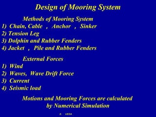
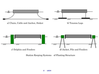
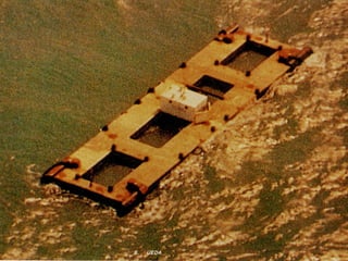
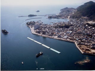
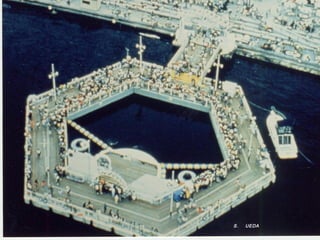
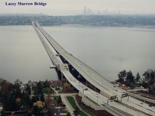
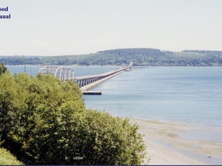
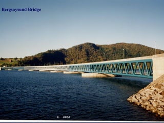
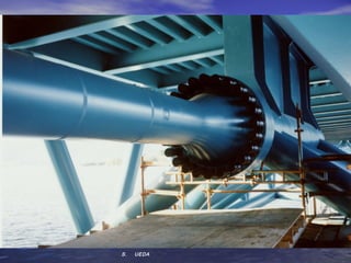
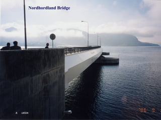
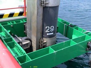
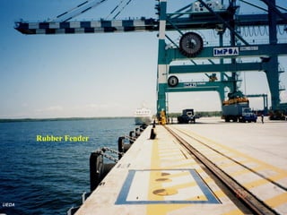
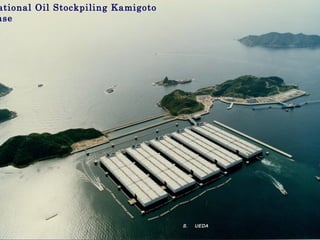
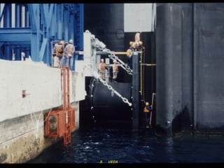
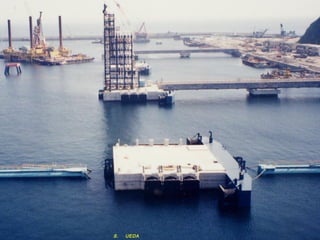
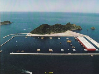
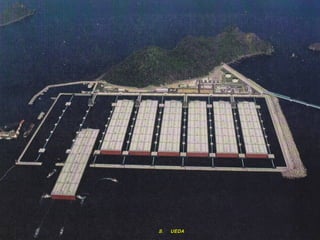
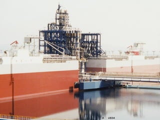
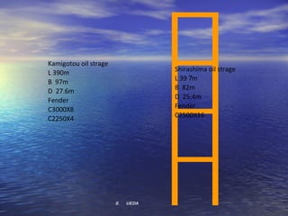
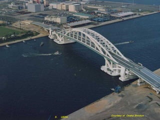
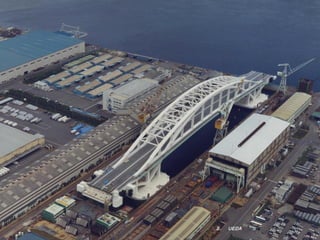
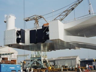
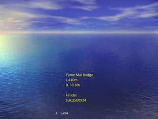
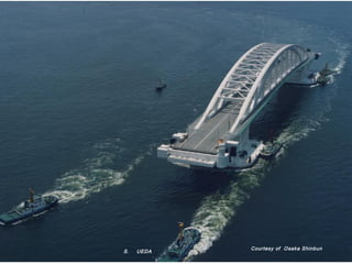
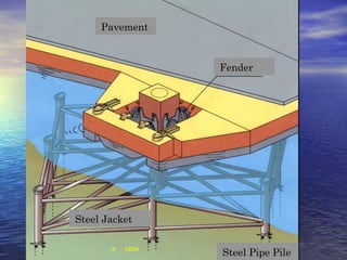
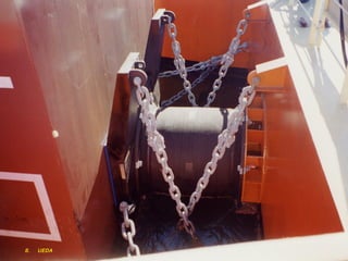
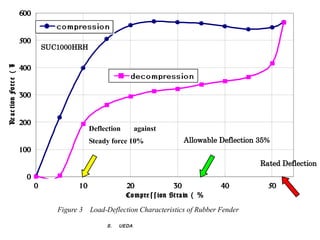
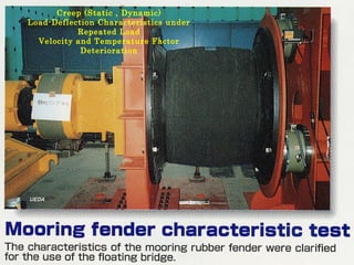
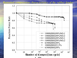
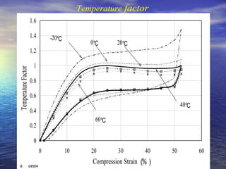
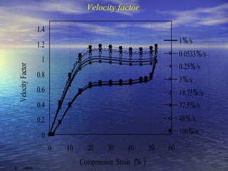
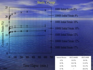
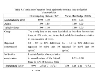
Recent Development of
 Floating Structures
  in Japan by use of
 Rubber Fenders for
     Mooring   

     7 th February 2012
   Shigeru UEDA
        S.   UEDA  
Design of Mooring System
        Methods of Mooring System
1) Chain, Cable , Anchor , Sinker
2) Tension Leg
3) Dolphin and Rubber Fenders
4) Jacket , Pile and Rubber Fenders
          External Forces
1)   Wind
2)   Waves, Wave Drift Force
3)   Current
4)   Seismic load
         Motions and Mooring Forces are calculated
                  by Numerical Simulation
                      S.   UEDA  
a) Chain, Cable and Anchor, Sinker                             b) Tension Legs


   c) Dolphin and Fenders                               d) Jacket, Pile and Fenders

                 Station Keeping Systems of Floating Structure


                      S.   UEDA   UEDA 2007     7 /09/2007
                                      S.   UEDA 2
                              S.   MTEC  
                                 S.   UEDA  
S.   UEDA  
S.   UEDA  
S.   UEDA  
Lacey Murrow Bridge


                      S.   UEDA  
ood  
anal


        S.   UEDA
Bergsoysund Bridge


                     S.   UEDA  
S.   UEDA  
Nordhordland Bridge


S.   UEDA  
S.   UEDA  
Rubber Fender


  UEDA  
ational Oil Stockpiling Kamigoto
ase


                                   S.   UEDA  
S.   UEDA  
S.   UEDA  
S.   UEDA  
S.   UEDA  
S.   UEDA  
Kamigotou oil strage
L 390m                             Shirashima oil strage
                                   L 397 m
B 97m
                                   B 82m
D 27.6m
                                   D 25.4m
Fender
                                   Fender
C3000X8
                                   C2500X16
C2250X4


                       S.   UEDA
Courtesy of Osaka Shinbun
S.   UEDA
S.   UEDA
S.   UEDA  
Yume Mai Bridge
       L 410m
       B 33.8m

       Fender
       SUC2500X24


S.   UEDA
Courtesy of Osaka Shinbun
S.   UEDA
S.   UEDA     Courtesy of Osaka Shinbun
Design of Connection
    Finger Joint
   Modular Joint
    Rubber Joint
 Rolling Leaf Joint


                       S.   UEDA  
S.   UEDA  
S.   UEDA  
S.   UEDA  
Final Unit Jointed
1999


      S.   UEDA
                     Courtesy of Asahi Shinbun
Mega   Float  
Ph-1  1995-1997  
300m×60m×2m
Ph-2  1998-2000 
1000m×121m× 3 m


           Phase-2


            S.   UEDA     Courtesy of Okamura
S.   UEDA   Courtesy of Asahi Shinbun
Pavement


                     Fender


Steel Jacket

       S.   UEDA  
                     Steel Pipe Pile
S.   UEDA  
600


                          500
                                    SUC1000HRH
Re a c tion Fo rc e (k
                     N)


                          400


                          300


                          200
                                                  Deflection       against
                                                  Steady force 10%                Allowable Deflection 35%
                          100
                                                                                                       Rated Deflection
                           0
                                0            10                20                30            40        50
                                                               Co m pre s s ion St ra in (%)

                                       Figure 3 Load-Deflection Characteristics of Rubber Fender

                                                       S.   UEDA
Creep (Static , Dynamic)
   Load-Deflection Characteristics under
              Repeated Load
     Velocity and Temperature Factor
               Deterioration


S.   UEDA  
Repeated compression characteristics of the rubber fender
                          1.2


                          1.0
   Reaction Force Ratio


                          0.8


                          0.6

                                                                      100H(RH)50%NO.1
                          0.4                                         100H(RH)50%NO.2
                                                                      100H(RH)20%NO.1
                                                                      100H(RH)20%NO.2
                          0.2                                         630H(RH)30%
                                                                      100H(RH)52.5%
                                                                      630H(RH)20%
                          0.0                       2            3     4         5        6    7
                                1   10         10           10        10    10       10       10
                                         Numb e r o f C o mp re s s io n c yc le s
                                                        S.   UEDA  
Temperature factor
                     1.6

                     1.4       -20℃
                                              0℃       20℃
                     1.2

                      1
Temperature Factor


                     0.8

                     0.6
                                                                             40℃
                     0.4
                                               60℃
                     0.2

                      0
                           0          10      20        30        40    50         60

S.   UEDA  
                                               Compression Strain (%)
Velocity factor

                    1.4
                    1.2                                               1%/s
                                                                      0.0533%/s
                     1
                                                                      0.25%/s
  Velocity Factor


                    0.8
                                                                      3%/s
                    0.6                                               18.75%/s
                    0.4                                               37.5%/s
                    0.2                                               48%/s
                     0                                                100%/s
                          0   10     20    30     40        50   60
                                   Compression Strain (%)
S.   UEDA  
Static Creep
                          25
                                                                 100H Initial Strain 8%

                          20                                     1000H Initial Strain 8%
                                                                 100H Initial Strain 10%
 Compression Strain (%)


                          15
                                                                 1000H Initial Strain 10%
                          10                                     100H Initial Strain 12%
                                                                 1000H Initial Strain 12%
                          5
                                                                 100H Initial Strain 17%
                          0
                               0   100 200 300 400 500 600 700    Initial Strain   SUC1000H   SUC100H
                                                                      8%            9.5 %      9.8 %
                                                                      10 %          12.3 %     11.9 %

                                         Time Elapse (min.)           12 %          14.3 %     15.1 %
S.   UEDA                                                             17 %            -        23.3 %
B
Reac                           B’
tion       A   C A’
For                           C’
ce
                         D’

           Compression
           Strain


                                            Standard Performance


                                     Compression Strain(%)
       S.   UEDA                    Compression Strain
Table 5.1 Variation of reaction force against the nominal load-deflection
                                      characteristics
                        Oil Stockpiling Station (1999)        Yume-Mai Bridge (2002)
Manufacturing error              0.90 – 1.10                        0.95 – 1.05
Aging                            1.00 – 1.05                        1.00 – 1.05
Velocity factor                  1.00 – 1.10                        1.00 – 1.05
Creep                  The steady load or the mean load shall be less than the reaction
                       force at 10% strain, and to use the load-deflection characteristics
                       in consideration of creep.
Repeated               0.8 – 0.9 (at 40% deflection 0.9 – 1.0 (at 20% deflection
compression            repeated for more than 10 repeated for more than 10
                       cycles)                      cycles)
Inclination            Load-deflection characteristics
compression            in consideration of the lateral              0.95 – 1.00
                       force as 10% of the axial force
Temperature factor        0.95 – 1.25 (at 0 – 50oC)         0.95 – 1.25 (at 15 – 45oC)
                          S.   UEDA  
ational Oil Stockpiling Kamigoto
ase


   Thank you very much
     for your patience


                       S.   UEDA

Floating structures

  • 1.
    Recent Development of Floating Structures in Japan by use of Rubber Fenders for Mooring    7 th February 2012 Shigeru UEDA S.   UEDA  
  • 2.
    Design of MooringSystem Methods of Mooring System 1) Chain, Cable , Anchor , Sinker 2) Tension Leg 3) Dolphin and Rubber Fenders 4) Jacket , Pile and Rubber Fenders External Forces 1) Wind 2) Waves, Wave Drift Force 3) Current 4) Seismic load Motions and Mooring Forces are calculated by Numerical Simulation S.   UEDA  
  • 3.
    a) Chain, Cableand Anchor, Sinker b) Tension Legs c) Dolphin and Fenders d) Jacket, Pile and Fenders Station Keeping Systems of Floating Structure S.   UEDA   UEDA 2007     7 /09/2007 S.   UEDA 2 S.   MTEC   S.   UEDA  
  • 4.
  • 5.
  • 6.
  • 7.
    Lacey Murrow Bridge S.   UEDA  
  • 8.
    ood   anal S.   UEDA
  • 9.
    Bergsoysund Bridge S.   UEDA  
  • 10.
  • 11.
  • 12.
  • 13.
  • 14.
    ational Oil StockpilingKamigoto ase S.   UEDA  
  • 15.
  • 16.
  • 17.
  • 18.
  • 19.
  • 20.
    Kamigotou oil strage L390m Shirashima oil strage L 397 m B 97m B 82m D 27.6m D 25.4m Fender Fender C3000X8 C2500X16 C2250X4 S.   UEDA
  • 21.
    Courtesy of OsakaShinbun S.   UEDA
  • 22.
  • 23.
  • 24.
    Yume Mai Bridge L 410m B 33.8m Fender SUC2500X24 S.   UEDA
  • 25.
    Courtesy of OsakaShinbun S.   UEDA
  • 26.
    S.   UEDA  Courtesy of Osaka Shinbun
  • 27.
    Design of Connection Finger Joint Modular Joint Rubber Joint Rolling Leaf Joint S.   UEDA  
  • 28.
  • 29.
  • 30.
  • 31.
    Final Unit Jointed 1999 S.   UEDA Courtesy of Asahi Shinbun
  • 32.
    Mega   Float  Ph-1  1995-1997   300m×60m×2m Ph-2  1998-2000  1000m×121m× 3 m Phase-2 S.   UEDA   Courtesy of Okamura
  • 33.
    S.   UEDA Courtesy of Asahi Shinbun
  • 34.
    Pavement Fender Steel Jacket S.   UEDA   Steel Pipe Pile
  • 35.
  • 36.
    600 500 SUC1000HRH Re a c tion Fo rc e (k N) 400 300 200 Deflection against Steady force 10% Allowable Deflection 35% 100 Rated Deflection 0 0 10 20 30 40 50 Co m pre s s ion St ra in (%) Figure 3 Load-Deflection Characteristics of Rubber Fender S.   UEDA
  • 37.
    Creep (Static ,Dynamic) Load-Deflection Characteristics under Repeated Load Velocity and Temperature Factor Deterioration S.   UEDA  
  • 38.
    Repeated compression characteristicsof the rubber fender 1.2 1.0 Reaction Force Ratio 0.8 0.6 100H(RH)50%NO.1 0.4 100H(RH)50%NO.2 100H(RH)20%NO.1 100H(RH)20%NO.2 0.2 630H(RH)30% 100H(RH)52.5% 630H(RH)20% 0.0 2 3 4 5 6 7 1 10 10 10 10 10 10 10 Numb e r o f C o mp re s s io n c yc le s S.   UEDA  
  • 39.
    Temperature factor 1.6 1.4 -20℃ 0℃ 20℃ 1.2 1 Temperature Factor 0.8 0.6 40℃ 0.4 60℃ 0.2 0 0 10 20 30 40 50 60 S.   UEDA   Compression Strain (%)
  • 40.
    Velocity factor 1.4 1.2 1%/s 0.0533%/s 1 0.25%/s Velocity Factor 0.8 3%/s 0.6 18.75%/s 0.4 37.5%/s 0.2 48%/s 0 100%/s 0 10 20 30 40 50 60 Compression Strain (%) S.   UEDA  
  • 41.
    Static Creep 25 100H Initial Strain 8% 20 1000H Initial Strain 8% 100H Initial Strain 10% Compression Strain (%) 15 1000H Initial Strain 10% 10 100H Initial Strain 12% 1000H Initial Strain 12% 5 100H Initial Strain 17% 0 0 100 200 300 400 500 600 700 Initial Strain SUC1000H SUC100H 8% 9.5 % 9.8 % 10 % 12.3 % 11.9 % Time Elapse (min.) 12 % 14.3 % 15.1 % S.   UEDA   17 % - 23.3 %
  • 42.
    B Reac B’ tion A C A’ For C’ ce D’ Compression Strain Standard Performance Compression Strain(%) S.   UEDA Compression Strain
  • 43.
    Table 5.1 Variationof reaction force against the nominal load-deflection characteristics Oil Stockpiling Station (1999) Yume-Mai Bridge (2002) Manufacturing error 0.90 – 1.10 0.95 – 1.05 Aging 1.00 – 1.05 1.00 – 1.05 Velocity factor 1.00 – 1.10 1.00 – 1.05 Creep The steady load or the mean load shall be less than the reaction force at 10% strain, and to use the load-deflection characteristics in consideration of creep. Repeated 0.8 – 0.9 (at 40% deflection 0.9 – 1.0 (at 20% deflection compression repeated for more than 10 repeated for more than 10 cycles) cycles) Inclination Load-deflection characteristics compression in consideration of the lateral 0.95 – 1.00 force as 10% of the axial force Temperature factor 0.95 – 1.25 (at 0 – 50oC) 0.95 – 1.25 (at 15 – 45oC) S.   UEDA  
  • 44.
    ational Oil StockpilingKamigoto ase Thank you very much for your patience S.   UEDA