Downloaded 177 times


![www.ChemicalEngineeringGuy.com
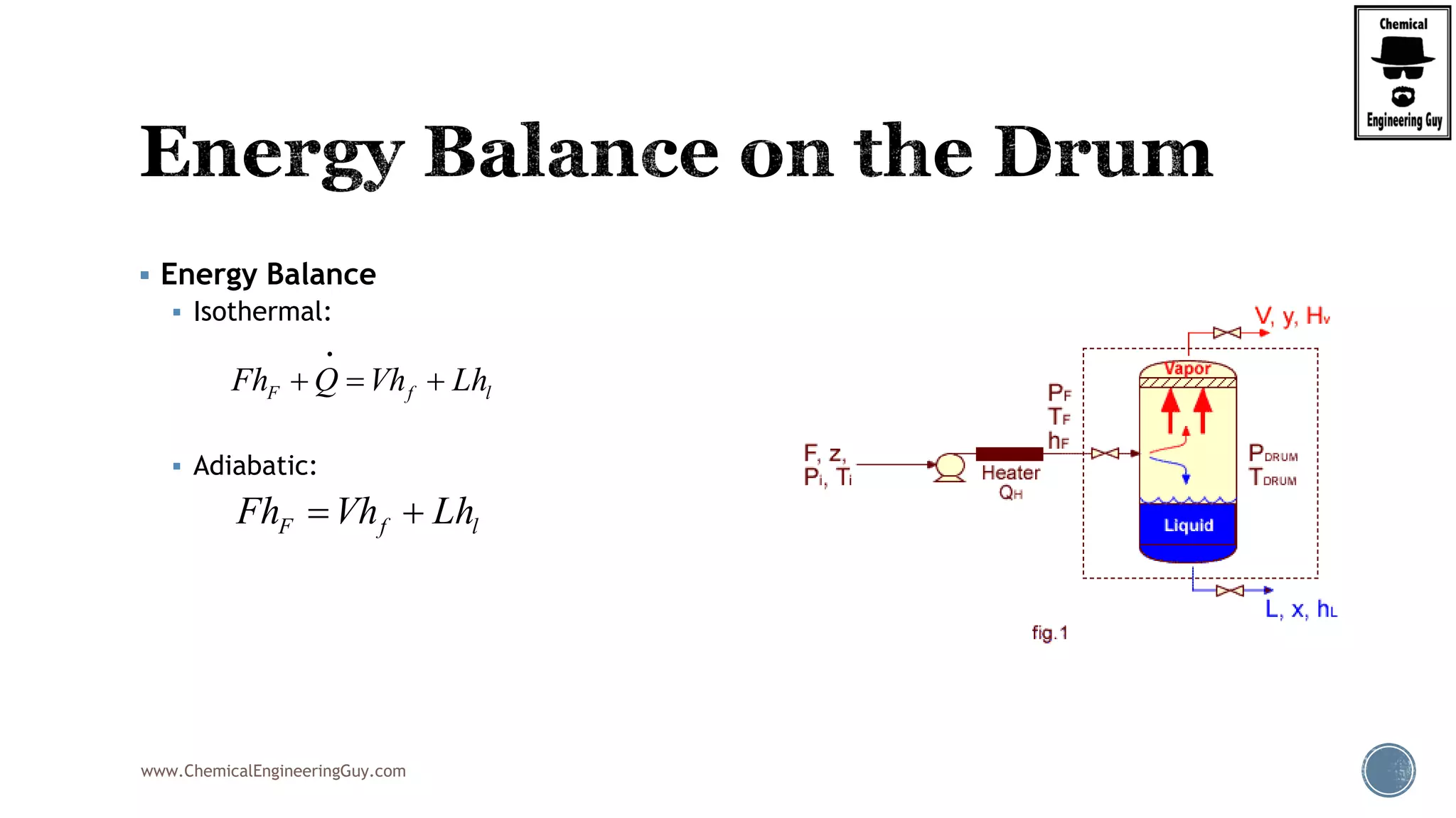
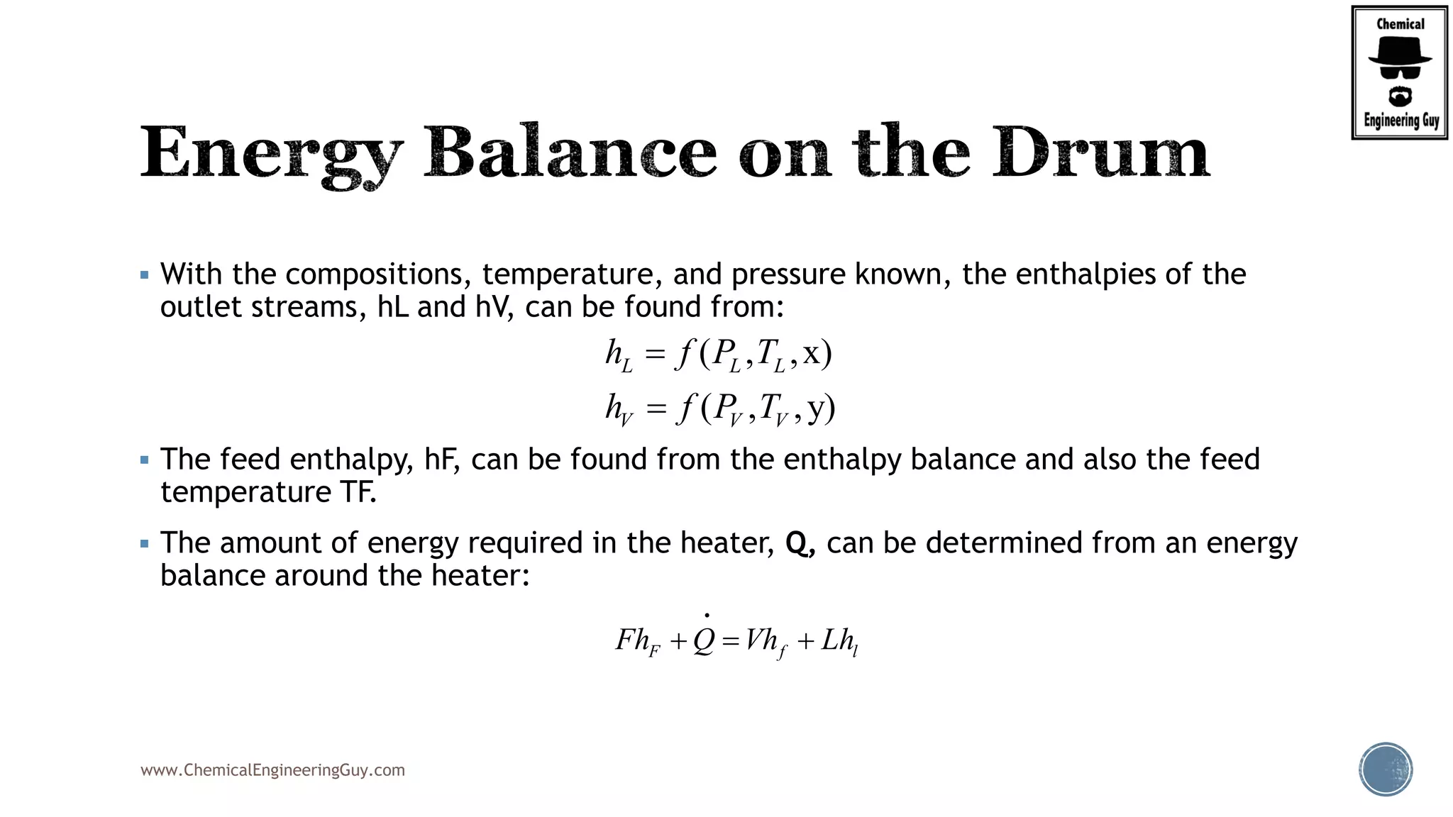
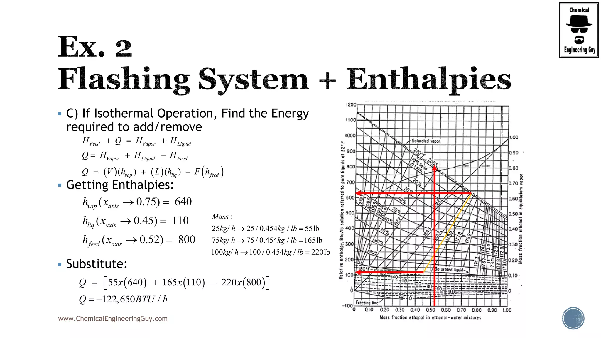
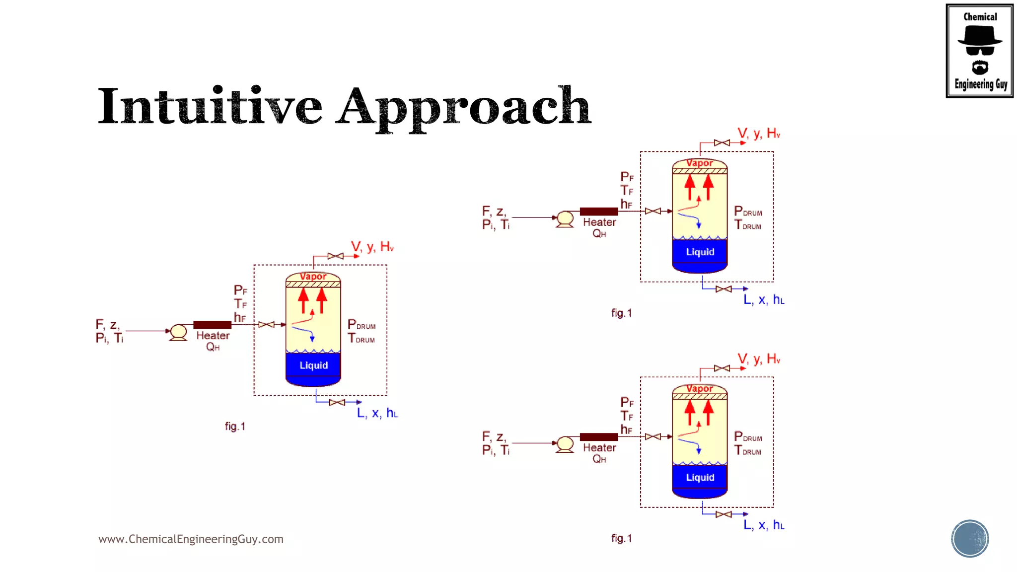
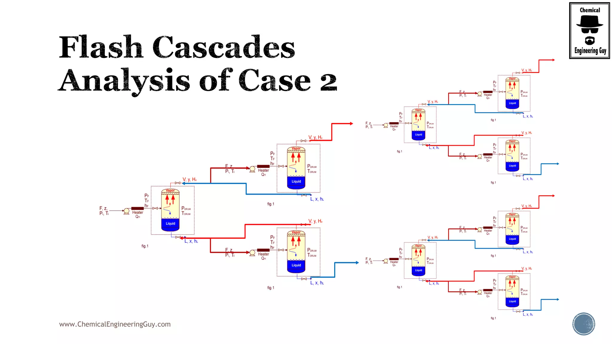
Finally, the heat balance:
( , , ) ( , , )
( , , ) ( , , )
[ ( , , ) ( , , )]
hx in in F F F F
hx F F F in in F
hx F F F in in F
Q Fh P T z Fh P T z
Q Fh P T z Fh P T z
Q F h P T z h P T z
](https://image.slidesharecdn.com/flashdistillationslideshare2of3-191031011833/75/Flash-Distillation-in-Chemical-and-Process-Engineering-Part-2-of-3-95-2048.jpg)


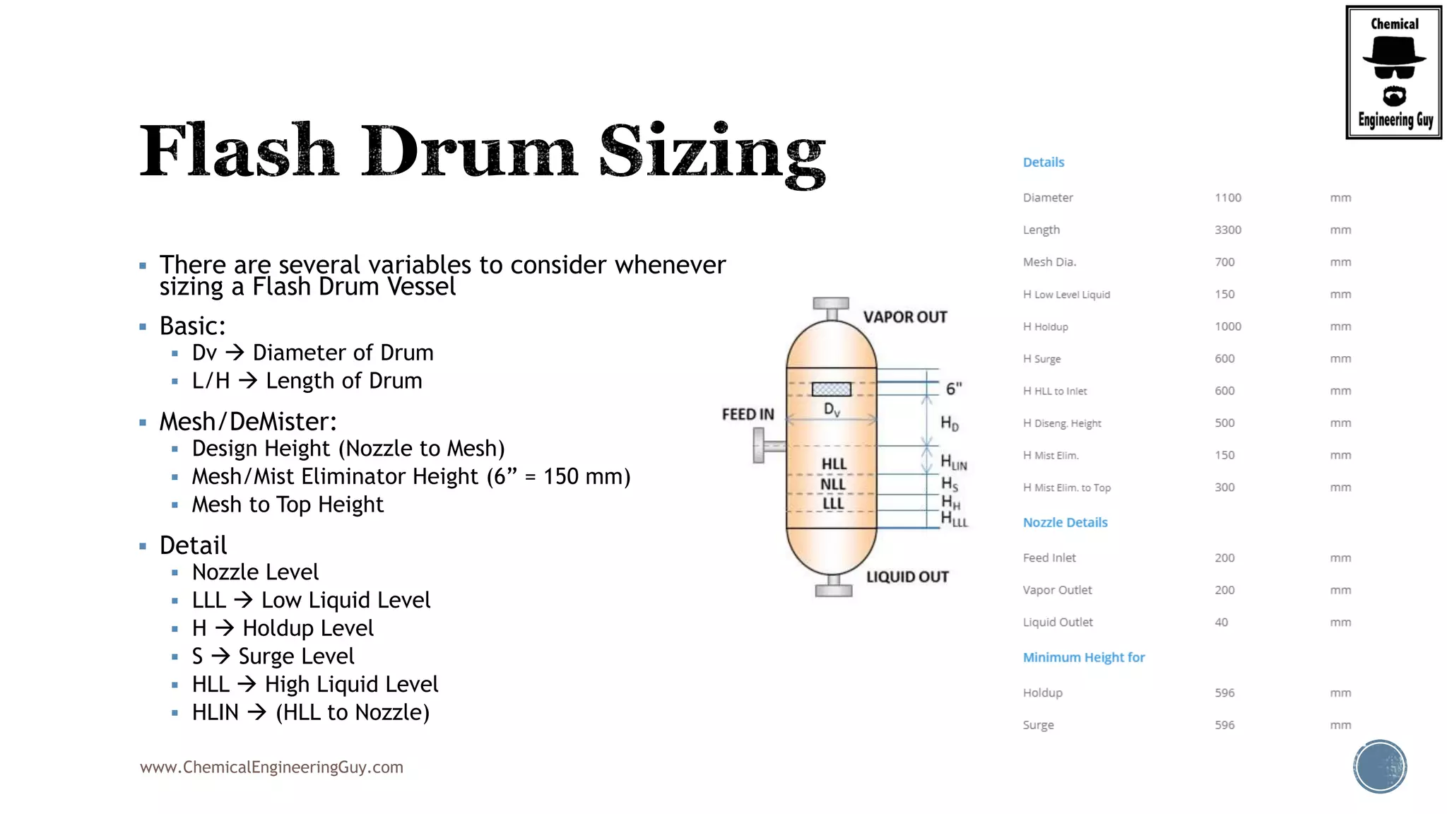


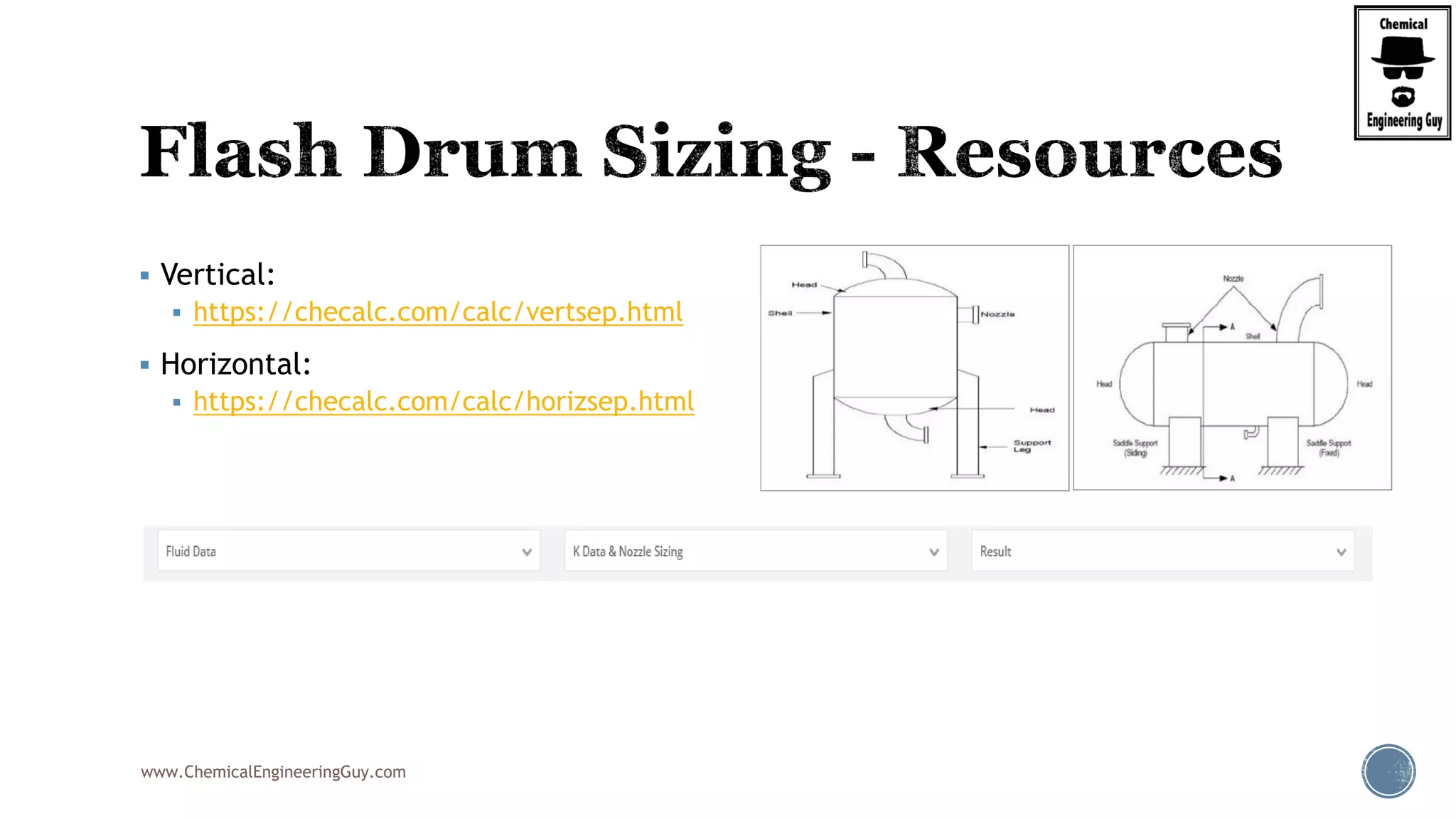


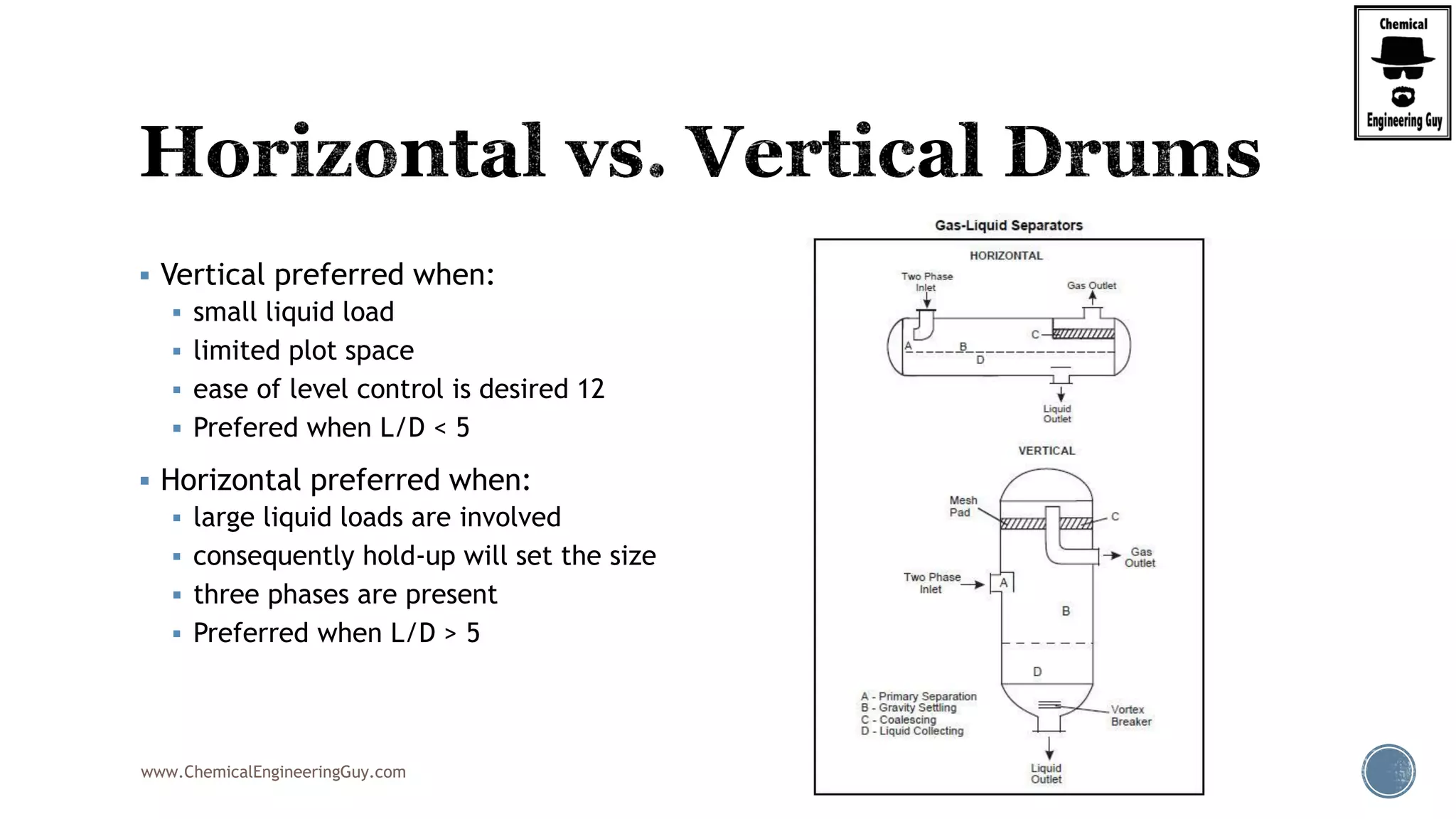
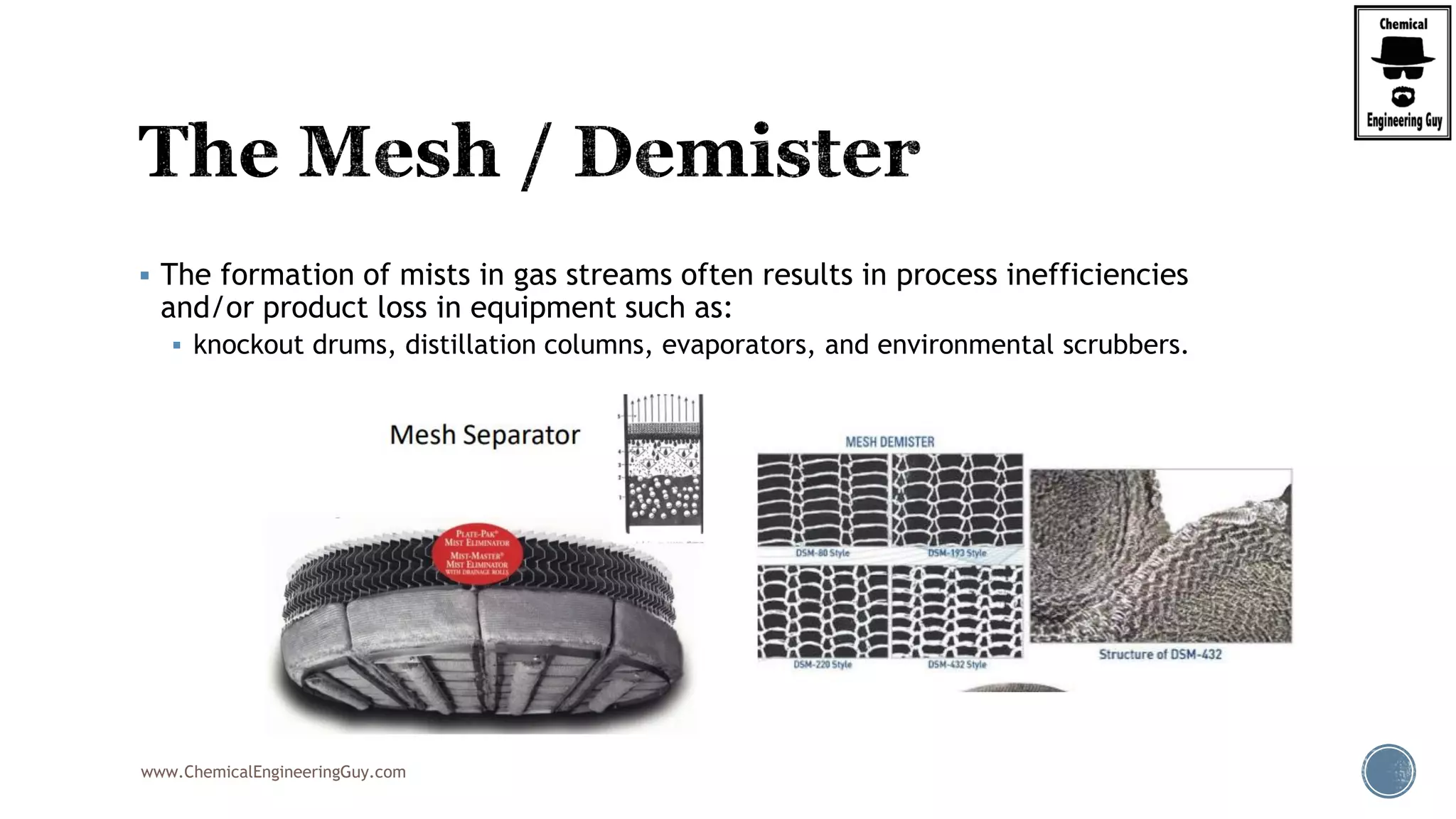
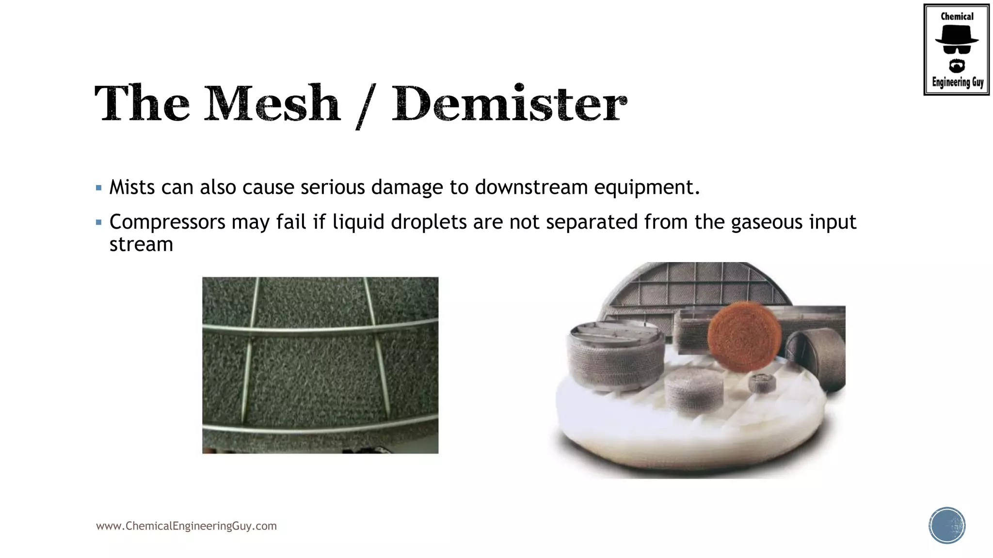
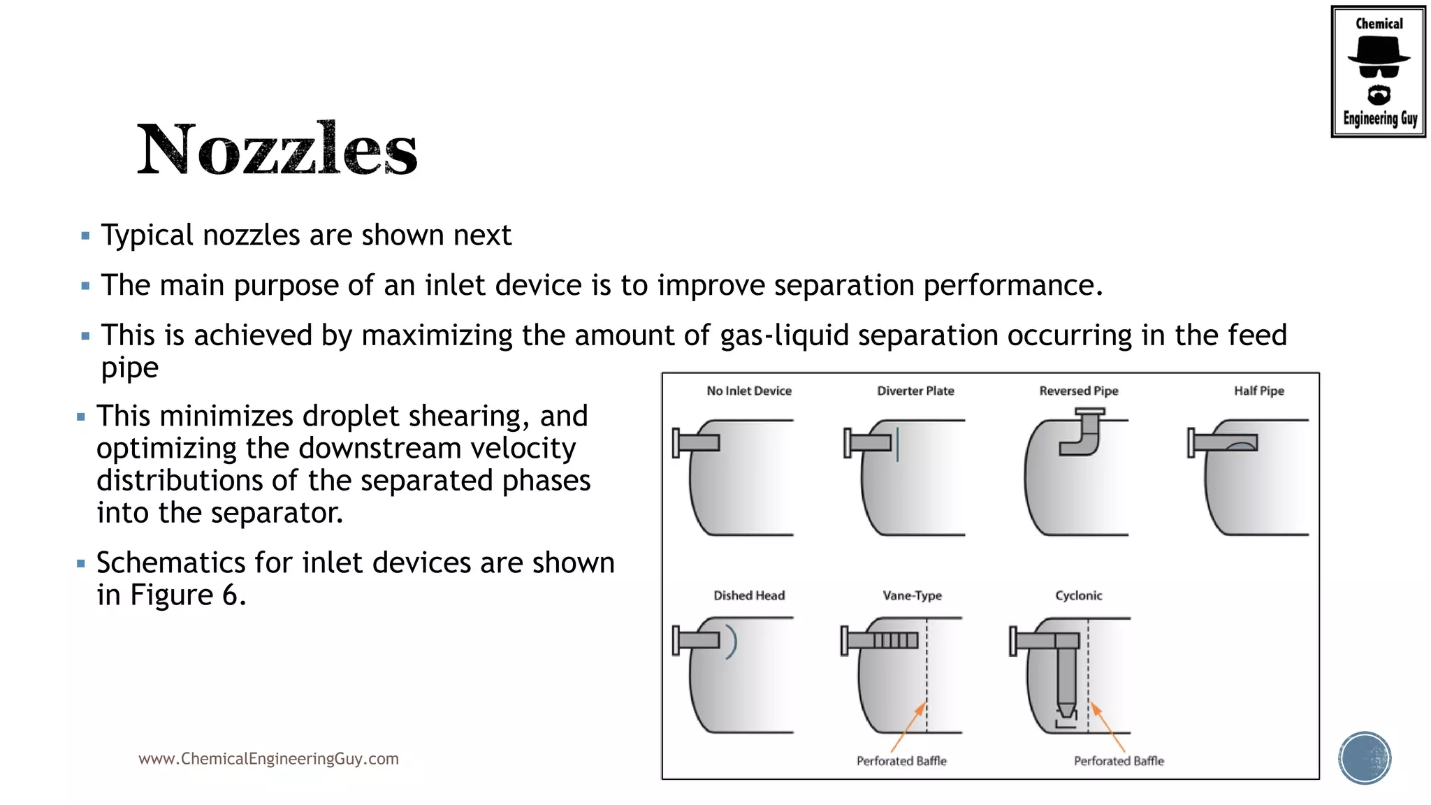
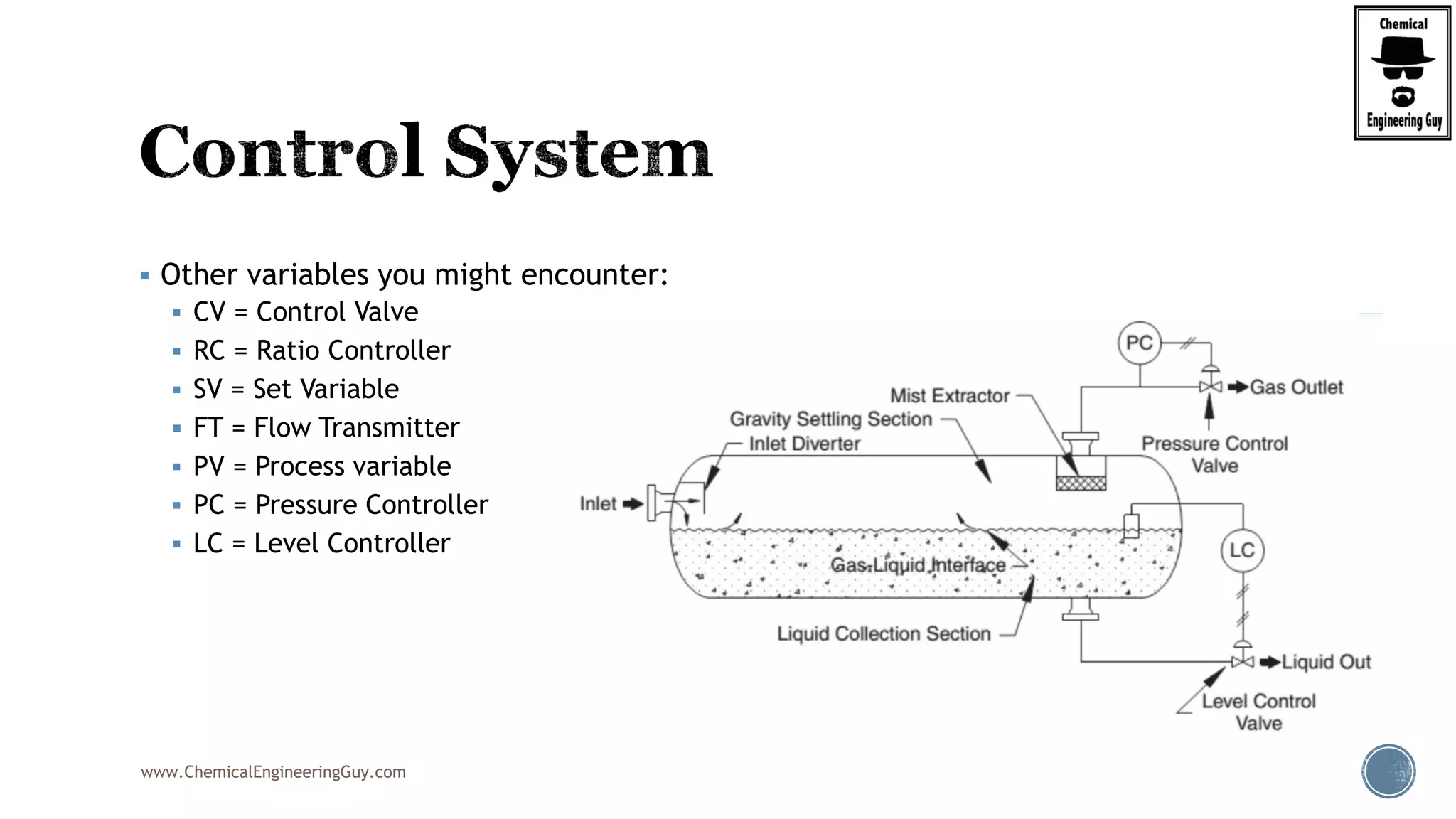
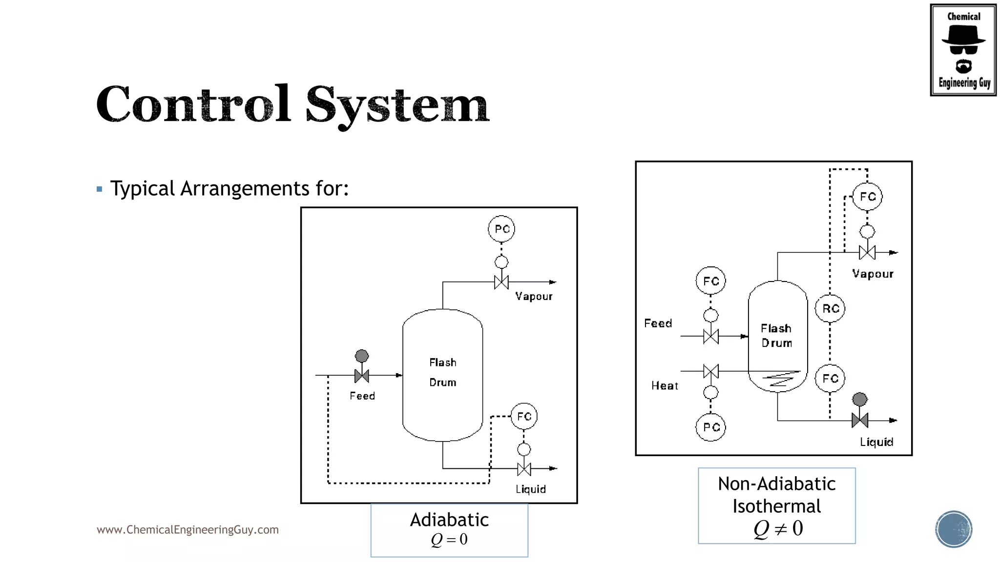
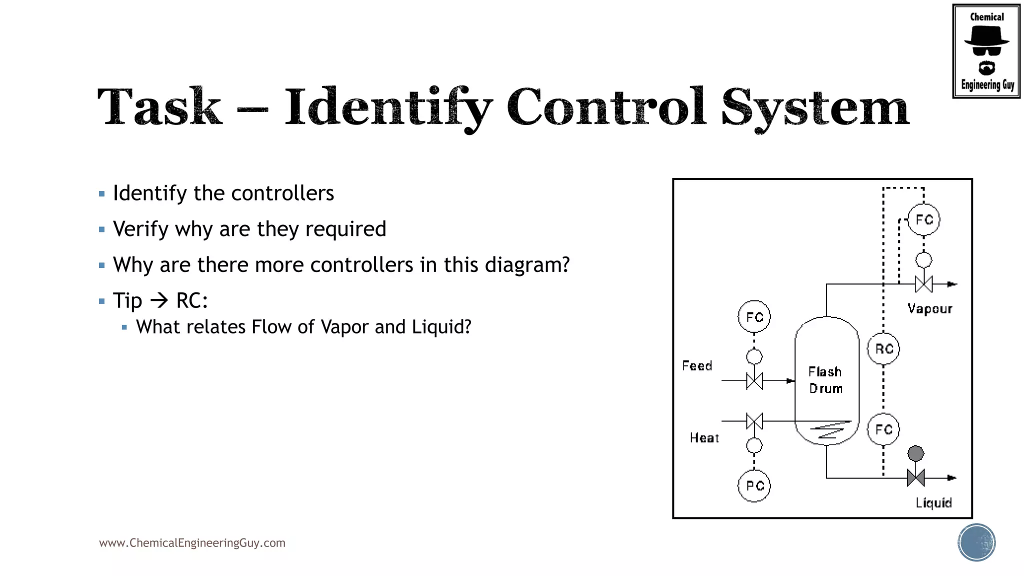
The document provides an overview of drum design preferences for liquid separation systems, discussing the use of vertical and horizontal configurations based on liquid load and hold-up times. It details control systems necessary for effective operation, such as flow, pressure, temperature, and liquid level controls in various separation processes like flash vessels and distillation. Additionally, it emphasizes the significance of proper design in mitigating mist formation that could lead to equipment failure or inefficiencies.


