Downloaded 34 times
![International Journal of Scientific & Engineering Research, Volume 9, Issue 2, Feburary-2018
ISSN 2229-5518
2 METHODS
Calculation Models: API RP-521 includes the calculation of
thermal radiation, noise and surface temperature.
F factors calculation- The F Factor or fraction of combustion
heat radiated from a flame is the most important single
parameter in the calculation of thermal radiation
calculation
The fraction of heat radiated is an overall characteristic of
the flame, which can be affected by the following variables:
• Gas composition
• Flame type
• State of air-fuel mixing
• Soot/smoke formation
• Quantity of fuel being burned
• Flame temperature
• Flare burner design
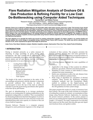
F factors calculation can be done using following equations,
they can be broadly categorized as empirically derived and
theoretically derived:
Empirically derived:
Kent, 1964(Correlation based on mole weight)-
Applicable for:
• Hydrocarbons, f = 0.4
• Propane, f = 0.33
• Methane, f = 0.2
𝑭 = 𝟎. 𝟐√
𝟓𝟎. 𝐌𝐖 + 𝟏𝟎𝟎
𝟗𝟎𝟎
Tan, 1967(based on mole weight)
Only applicable for three F- Factor value
Methane = 0.20 (MW = 16)
Propane = 0.33 (MW = 44)
Higher molecular weight hydrocarbons = 0.40
𝑭𝒔 = 𝟎. 𝟎𝟒𝟖 √𝑴𝑾
Cook et al., 1987a (Correlation based on exit velocity)
Values of the fraction of heat radiated varied from 0.017 to
0.344, the mean value over all tests being 0.187 (Cook et al.,
1987a).
𝝌 =
𝒑
𝑸
=
𝒑
𝒎𝒋 . 𝜟𝒉𝒄
P= E Af
Chamberlain, 1987(Empirically derived)
The Fs factor for high velocity 6” diameter tests fall below
the curve because the flames are smaller and spectrally
different from those at higher flow rates. The correlation,
therefore, referred to large flares typical of offshore flare
system design flow rates. For small flames at high velocity,
the equation will over predict Fs, and flare systems designed
for these cases will be conservative unless a more
appropriate value of Fs is used.
Fs = 0.11 + 0.21 e -0.00323Uj
Mod. Chamberlain Method (Correlation based on mole
weight and exit velocity)
Fs = [0.11 + 0.21 e -0.00323Uj] . f(MW)
Where,
• f(MW) = 1, MW<21
• f (MW) = (MW/21) 0.5, 21< MW <60
• f (MW) = 1.69, 60< MW
Cook et al., 1987b
The complete model was validated by comparing
predictions with measured values of incident radiation
obtained in 57 field scale experiments. It was found that over
80% of all predictions were within ±30% of the
measurements.
f = 0.321 – 0.00041uj
Theoretically derived:
API, 1969
According to API RP 521, flare stack calculation includes
thermal radiation, surface temperatures and noise models.
Common approach to determining the flame radiation to a
point of interest is to consider the flame to have a single
radiant epicentre and to use the following empirical
equation by Hajek and Ludwig may be used for both
subsonic and sonic flares
𝒙 = √
𝛕. 𝐅. 𝐐
𝟒. 𝛑. 𝐤
Applicable conditions: Brzustowski and Sommer (1973)
suggested that this model is quite accurate close to the flame.
Chamberlain (1987) predicted it could only predict thermal
radiation accurately in the far field (the opposite to what
Brzustowski and Sommer (1973) reported)
Limitations: Ignores wind effects and calculates the distances
assuming the centre of radiation is at the base of the flame
(at the flare tip), not in the centre.
976
IJSER © 2018
http://www.ijser.org
IJSER](https://image.slidesharecdn.com/flare-radiation-mitigation-analysis-of-onshore-oil-gas-production-refining-facility-for-a-low-cost-d-180327053022/85/Flare-radiation-mitigation-analysis-of-onshore-oil-gas-production-refining-facility-for-a-low-cost-de-bottlenecking-using-computer-aided-techniques-2-320.jpg)
![International Journal of Scientific & Engineering Research, Volume 9, Issue 2, Feburary-2018
ISSN 2229-5518
Brzustowski and Sommer, 1973
Equation extensively verified for large windblown flares.
𝑭 =
𝟒𝛑𝐊𝐃 𝟐
𝐐 𝐂𝐨𝐬𝛉
Leahey et al., 1979
Based on the geometry of the flame. They represented the
flame surface as the frustum of a right cone. Theoretical
values are considerably higher than observed values, in
wind conditions.
𝝑 =
𝛆 𝛔𝑻 𝟒(𝑹 + 𝐑𝐨)√(𝑳 𝟐 + (𝑹 + 𝐑𝐨) 𝟐
∆𝑯𝐑𝐨 𝟐 𝑾 𝟎
This method do not give limitations in the applicability of
the theoretical equation for determining the F-factor. Limited
test conditions are provided on the graphs, but no other
experimental conditions were stated.
Oenbring and Sifferman, 1980
This method assumed a point-source of radiance, located at
one-half the flare flame length.
𝑭 =
𝟒𝛑𝐊𝐃 𝟐
𝐐
Flame Length Method
Flame length is calculated from heat released using
following equation.
𝑳 = 𝑰𝟏 [
𝑸
𝑵
]
𝑰𝟐
Where
L is flame length in m
Q is heat release in J/s
N is number of tips
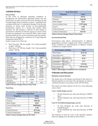
the constants I1 and I2 take the following values for
different tip types
Table 1: Constants I1 and I2 take the following values for
different tip types
Thermal radiation effects:
Many investigations have been undertaken to determine the
effect of thermal radiation on human skin. Using human
subjects, Stoll and Greene [8] found that with an intensity of
6.3 kW/m2, the pain threshold is reached in 8 s and
blistering occurs in 20 s. On the bare skin of white rats, an
intensity of 6.3 kW/m2 produces burns in less than 20 s. The
same report indicates that an intensity of 23.7 kW/m2 causes
burns on the bare skin of white rats in approximately 6s.
The flare owner/operator shall determine the need for a
solar-radiation-contribution adjustment to the values given
in Table 2 on a case-by-case basis.
Recommended design thermal radiation for personnel
Permissible
design level
Conditions
9.46(3000)
kW/m2
(Btu/h·ft2)
Maximum radiant heat intensity at any
location where urgent emergency action by
personnel is required. When personnel
enter or work in an area with the potential
for radiant heat intensity greater than 6.31
kW/m2 (2 000 Btu/h·ft2), then radiation
shielding and/or special protective apparel
(e.g. a fire approach suit) should be
considered.
6.31 (2 000)
kW/m2
(Btu/h·ft2)
Maximum radiant heat intensity in areas
where emergency actions lasting up to 30 s
can be required by personnel without
shielding but with appropriate clothing a
4.73 (1 500)
kW/m2
(Btu/h·ft2)
Maximum radiant heat intensity in areas
where emergency actions lasting 2 min to 3
min can be required by personnel without
shielding but with appropriate clothing a
1.58 (500)
kW/m2
(Btu/h·ft2)
Maximum radiant heat intensity at any
location where personnel with appropriate
clothing a can be continuously exposed
Table 2: Exposure times as per API-521
a Appropriate clothing consists of hard hat, long-sleeved
shirts with cuffs buttoned, work gloves, long-legged pants
and work shoes. Appropriate clothing minimizes direct skin
exposure to thermal radiation.
SAFETY PRECAUTION — It is important to recognize that
personnel with appropriate clothing a cannot tolerate
thermal radiation at 6.31 kW/m2 (2 000 Btu/h•ft2) for more
than a few seconds.
Table 3: Exposure times necessary to reach the pain
threshold
Tip Type l1 l2
Pipe flare 0.00331 0.4776
Single Burner Sonic 0.00241 0.4600
Multiple Burner
Sonic
0.00129 0.5000
Radiation intensity,
kW/m2 (Btu/h·ft2)
Time-to-pain threshold
(Seconds)
1.74 (550) 60
2.33(7400) 40
2.90(920) 30
4.73(1500) 16
6.94(2200) 9
9.46(3000) 6
11.67(3700 4
1987(6300) 2
977
IJSER © 2018
http://www.ijser.org
IJSER](https://image.slidesharecdn.com/flare-radiation-mitigation-analysis-of-onshore-oil-gas-production-refining-facility-for-a-low-cost-d-180327053022/85/Flare-radiation-mitigation-analysis-of-onshore-oil-gas-production-refining-facility-for-a-low-cost-de-bottlenecking-using-computer-aided-techniques-3-320.jpg)
![International Journal of Scientific & Engineering Research, Volume 9, Issue 2, Feburary-2018
ISSN 2229-5518
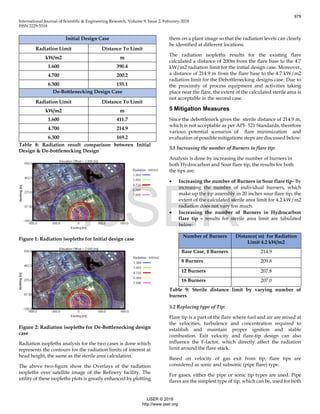
Figure 5: Radiation Isopleths for Shielding design case in
Nothing- Easting Plane
Figure 6: Temperature Isopleths for Shielding design case
in Downwind Elevation Plane
6 DISCUSSION
In addition to the above mitigation steps discussed in the
paper there are some other process modification steps as
well, by which significant reductions in flaring can be made,
the process is:
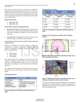
Flare gas recovery- for Minimize flaring and to reduce the
facility wide air emission, a refinery process for reusing
waste gas as fuel gas. Flare gas recovery systems lower
emissions by recovering flare gases before they are
combusted by the flare. In practice, a flare gas recovery
system collects gas from the flare header before it reaches the
flare, compresses the gas and cools it for re-use in the
refinery-fuel gas system:
Figure 7: Main Flare gas recovery system [12]
7 Conclusion:
Flares are essential refinery safety equipment. They provide
a means to ensure the safe and efficient combustion of gases
that would otherwise be released to the environment.
For debottlenecking of refinery case various flaring event
was analyzed, to assure that Process unit vent gases are
safely burned to minimize the potential for explosion, fire, or
other unsafe conditions, in which different limiting
parameter for maximum flow: thermal radiation are
analyzed.
If the analyzed onshore facility operates at present with a
maximum flaring flow then it is recommended to implement
any of the following actions, according to economical or
operative possibilities:
• To diminish the maximum flaring flow, modifying
the process in order to achieve this goal without
compromising the production level
• To adopt a system of Solid Shield in order to
diminish radiation levels
• Varying LHV (Lower heating value) of Flare gas
which directly effects the efficiency of combustion
process in flares.
• To replace flare tip by another that is suitable for the
present levels of operation
• Incorporating minor process modifications like
Flare Gas Recovery unit
NOMENCLATURE
• F = fraction of heat radiated
• hc = net calorific value of combustion
• n = molar fraction
• m = molecular weight of the flared gas
• P = total radiative power (W)
• E = Emissive power (Wm-2)
• Af = Flame area (m2)
• Q = total heat release rate (W)
• mj = mass flow rate of gas exiting stack (kg-1)
981
IJSER © 2018
http://www.ijser.org
IJSER](https://image.slidesharecdn.com/flare-radiation-mitigation-analysis-of-onshore-oil-gas-production-refining-facility-for-a-low-cost-d-180327053022/85/Flare-radiation-mitigation-analysis-of-onshore-oil-gas-production-refining-facility-for-a-low-cost-de-bottlenecking-using-computer-aided-techniques-7-320.jpg)

The document analyzes flare radiation mitigation for an onshore oil and gas facility aiming to increase its capacity from 6.0 to 7.8 million metric tons per annum through low-cost de-bottlenecking. Using the Flaresim software, the study evaluates existing flare systems, calculating sterile areas and comparing initial and enhanced designs for thermal radiation limits. The results demonstrate the effectiveness of the de-bottlenecking approach in reducing environmental impacts while ensuring safety during operational emergencies.


