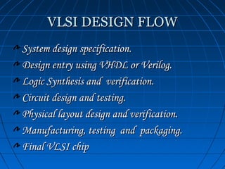
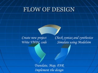
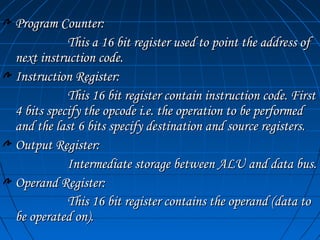
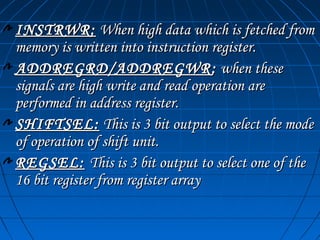
Department Of Electronics & Communication Engineering
  U.N.S.I.E.T. V.B.S. PURVANCHAL UNIVERSITY
                      JAUNPUR

      DESIGN OF 16 BIT
 MICROPROCESSOR USING VHDL
A PROJECT BY:
    Nishant Kumar Srivastava
    Jibran Hafeez
    Zeeshan Alam


GUIDED BY:
         Er. Shiv Chand Gupta
FLOW OF PRESENTATION
 VLSI Technology
   What is VLSI
   Design Flow

 Hardware Description Languages

VHDL basics
Project overview
Components of processor
Application and Future Aspects
Conclusion.
VLSI TECHNOLOGY
   What is VLSI
   Design Flow
VLSI
Very Large Scale Integration.

VLSI chips provide:
      Compactness,
      Low power consumption,
      Higher Reliability and speed,
      Significant cost savings.
VLSI DESIGN FLOW
System design specification.
Design entry using VHDL or Verilog.
Logic Synthesis and verification.
Circuit design and testing.
Physical layout design and verification.
Manufacturing, testing and packaging.
Final VLSI chip
HARDWARE
DESCRIPTION
LANGUAGES

  VHDL BASICS
VHDL BASICS
Very high speed integrated circuit Hardware
Description Language.
It is being used for documentation, verification,
and synthesis of large digital designs.
It employs the structural, data flow, and
behavioral methods of hardware description.
 An Entity declaration provides the complete
input - output interface for a circuit
An Architecture describes the function and
structure of a circuit
PROJECT OVERVIEW
   DESIGN PARAMETERS
    FLOW OF DESIGN
DESIGN PARAMETERS
 16 bit Address and Data bus.
16 bit ALU.
16 bit Control unit, the heart of microprocessor.
Comparator to perform logical operations.
16 bit Register array for temporary storage of data.
Address register to point the current instruction.
Program counter to point the next instruction.
Instruction register to store the fetched instruction code.
Operation register .
Shift unit to perform Shift and rotate operations.
Out register for temporary storage of data.
Address (16 bit)                                                          Data (16 bit)


ADDRESS REG.                                                      INSTRUCTION
                               Addrreg
                               select                                 REG.
                                                            Instrreg.out
                                                                                  Instrregsel

                                          Progcntrrd
PROGRAM COUNTER                           Progcntrwr
                                                                                             VMA

                                                                                           W/ Rb
                                                                     CONTROL
                      Regsel                                                              CLOCK
                      Regwr
                                                                           UNIT           RESET
                      Regrd                             Opregse
   REGISTER                               OP. REG.      l                                 READY

    ARRAY
                                                                                    Compse
                                   Alusel                                           l
                                                                                  Compout
(A,B,C,D,E,F,G,H)
                                             ALU                  COMPARATOR
                                                 Shiftsel

                                         SHIFT UNIT

                                                 Outregr
                                         OUT   REG. Outregwr
                                                 d
FLOW OF DESIGN


Create new project    Check syntax and synthesize
Write VHDL code        Simulate using Modelsim


         Translate, Map, PAR
         Implement the design
SOFTWARE WINDOW
COMPONENTS OF
  PROCESSOR
   SYNTHESIS AND
   VERIFICATION
COMPONENTS
ALU
Shift Unit
Comparator
Address Register
Register Array
Program Counter
Instruction Register
Output Register
Operand Register
Control Unit
ALU


Two unsigned 16 bit inputs ‘a’ and ‘b’
Unsigned output ‘c’ of 16 bits,
Select line ‘s’ of 4 bit to select one of the
following operations performed by the ALU.
OPERATIONS PERFORMED BY
             ALU
PASS(0000): In this mode no operation is performed on the
operands. It just passes the data as it is.
AND (0001): This mode performs AND operation between
‘a’ and ‘b’ and the output is obtained on ‘c’.
OR (0010): This mode performs OR operation between ‘a’
and ‘b’ and the output is obtained on ‘c’.
NOT (0011): NOT operation is performed on ‘a’ and output
is given on line ‘c’.
XOR (0100): This mode performs XOR operation between
‘a’ and ‘b’ and the output is obtained on ‘c’.
ADD (0101): This mode performs ADD operation between
‘a’ and ‘b’ and the output is obtained on ‘c’.
SUB (0110): This mode performs SUB operation between
‘a’ and ‘b’ and the output is obtained on ‘c’.
INC (0111): This mode increments the data in ‘a’ and the
output is obtained on ‘c’.
DEC (1000): This mode Decrements the data in ‘a’ and
the output is obtained on ‘c’.
ZERO (1001): This mode provides a Zero output on ‘c’.
MUL (1010): This mode performs Multiplication
operation between ‘a’ and ‘b’ and the output is obtained on
‘c’.
DIV (1011): This mode performs Division operation
between ‘a’ and ‘b’ and the output is obtained on ‘c’.
BYTESWAP (1100): This mode will interchange the
upper and lower byte of ‘a’ and the output is obtained on
OTHER UNITS
Comparator:
            This unit compares two 16 bit data coming from ALU
and Operand register and gives one bit output to the control unit.
Shift Unit:
            The Shift unit performs operations like Shift left, Shift
right, Rotate left, Rotate right for bit manipulations
Address Register:
            This is a 16 bit register which is used to point a location
in memory space.
Register Array:
            This is an array of 8 registers used for temporary storage
of data.
Program Counter:
           This a 16 bit register used to point the address of
next instruction code.
Instruction Register:
           This 16 bit register contain instruction code. First
4 bits specify the opcode i.e. the operation to be performed
and the last 6 bits specify destination and source registers.
Output Register:
           Intermediate storage between ALU and data bus.
Operand Register:
           This 16 bit register contains the operand (data to
be operated on).
CONTROL UNIT
    This unit is the heart of Microprocessor which provides
    control and timing signals to other units. The various
    controlling signals are as follows:

   INSTRREG: This 16 bit line coming from Instruction
    Register is decoded in Control Unit to know the operation
    to be performed.
   CLOCK : This is a external signal to CU which is used for
    timing and synchronization of CU operations.
   COMPOUT : This one bit line coming from Comparator
    can be either high or low depending on the operations
    performed in the comparator.
   RESET : Used to reset or restart the operations of
    microprocessor.
READY : Provides synchronization between
microprocessor and external elements or devices
VMA - VALID MEMORY ADDRESS : This
signal is used to enable the memory chip for read and
write operations.
WRB - WRITE/ READ BAR : When high
memory write operation is enabled and when low
read operation is enabled.
COMPSEL: This is 3 bit output to select the mode
of operation of comparator.
ALUSEL: This is 4 bit output to select the mode of
operation of ALU.
REGWR / REGRD: When high write and read
operations performed in one of the register of register
array.
PROGCNTRWR/ PROGCNTRRD : when
these signals are high write and read operation are
performed in program counter.
OUTREGRD/OUTREGWR : when these
signals are high write and read operation are
performed in output register. Output register is used
for temporary storage of data during clock transition,
to prevent overwriting of data on data bus.
OPREGRD: When high data of operation register
moves into ALU.
INSTRWR: When high data which is fetched from
memory is written into instruction register.
ADDREGRD/ADDREGWR : when these
signals are high write and read operation are
performed in address register.
SHIFTSEL: This is 3 bit output to select the mode
of operation of shift unit.
REGSEL: This is 3 bit output to select one of the
16 bit register from register array
OPERATION OF CONTROL UNIT


             Execute the instruction.        Keep Reset high for 1 cycle.


  Control Unit decodes first 5 bits             VMA goes high
  And determines the instruction                WRb goes low.


                             If Ready is high
                  Data is stored on instruction register.
COMPLETE MICROPROCESSOR


Various pins of microprocessor are:-
  CLOCK
  RESET
  READY
  VMA
  WRB
  DATA BUS: It is 16 bit bus carry data between all the
  unit of processor and also exchange data with external world.
  ADDRESS BUS : It is 16 bit bus, used to address memory.
OPERATION CYCLE OF
        MICROPROCESSOR
Reset is kept high for 1 clock cycle. So that reset cycle
starts, output 0000h will be placed on address bus and
data bus.
The data from data bus gets copied in address and
program counter register.
Now, VMA goes high and WRB goes low.
Then if READY is high, the data on data bus will get
stored in instruction register.
Control unit takes first 5 bits (15 downto 11) from
instruction register to decode the type of operation.
Now first decoded instruction is executed.
Finally procedure of incrementing program counter starts.
FUTURE PLANS AND
            CONCLUSION
Since this is a new emerging field, we will try to
design and implement as many new designs as
possible,
We will also add as many new instructions as
possible,
From our project and related research, we have
learnt the whole “VLSI design flow”
Our project gives a way to verify, simulate and test
any design before manufacturing which is helpful
for saving time, cost and manpower in Industries.

First seminar

  • 1.
    Department Of Electronics& Communication Engineering U.N.S.I.E.T. V.B.S. PURVANCHAL UNIVERSITY JAUNPUR DESIGN OF 16 BIT MICROPROCESSOR USING VHDL
  • 2.
    A PROJECT BY: Nishant Kumar Srivastava Jibran Hafeez Zeeshan Alam GUIDED BY: Er. Shiv Chand Gupta
  • 3.
    FLOW OF PRESENTATION VLSI Technology What is VLSI Design Flow Hardware Description Languages VHDL basics
  • 4.
    Project overview Components ofprocessor Application and Future Aspects Conclusion.
  • 5.
    VLSI TECHNOLOGY What is VLSI Design Flow
  • 6.
    VLSI Very Large ScaleIntegration. VLSI chips provide: Compactness, Low power consumption, Higher Reliability and speed, Significant cost savings.
  • 7.
    VLSI DESIGN FLOW Systemdesign specification. Design entry using VHDL or Verilog. Logic Synthesis and verification. Circuit design and testing. Physical layout design and verification. Manufacturing, testing and packaging. Final VLSI chip
  • 8.
  • 9.
    VHDL BASICS Very highspeed integrated circuit Hardware Description Language. It is being used for documentation, verification, and synthesis of large digital designs. It employs the structural, data flow, and behavioral methods of hardware description. An Entity declaration provides the complete input - output interface for a circuit An Architecture describes the function and structure of a circuit
  • 10.
    PROJECT OVERVIEW DESIGN PARAMETERS FLOW OF DESIGN
  • 11.
    DESIGN PARAMETERS 16bit Address and Data bus. 16 bit ALU. 16 bit Control unit, the heart of microprocessor. Comparator to perform logical operations. 16 bit Register array for temporary storage of data. Address register to point the current instruction. Program counter to point the next instruction. Instruction register to store the fetched instruction code. Operation register . Shift unit to perform Shift and rotate operations. Out register for temporary storage of data.
  • 12.
    Address (16 bit) Data (16 bit) ADDRESS REG. INSTRUCTION Addrreg select REG. Instrreg.out Instrregsel Progcntrrd PROGRAM COUNTER Progcntrwr VMA W/ Rb CONTROL Regsel CLOCK Regwr UNIT RESET Regrd Opregse REGISTER OP. REG. l READY ARRAY Compse Alusel l Compout (A,B,C,D,E,F,G,H) ALU COMPARATOR Shiftsel SHIFT UNIT Outregr OUT REG. Outregwr d
  • 13.
    FLOW OF DESIGN Createnew project Check syntax and synthesize Write VHDL code Simulate using Modelsim Translate, Map, PAR Implement the design
  • 14.
  • 15.
    COMPONENTS OF PROCESSOR SYNTHESIS AND VERIFICATION
  • 16.
    COMPONENTS ALU Shift Unit Comparator Address Register RegisterArray Program Counter Instruction Register Output Register Operand Register Control Unit
  • 17.
    ALU Two unsigned 16bit inputs ‘a’ and ‘b’ Unsigned output ‘c’ of 16 bits, Select line ‘s’ of 4 bit to select one of the following operations performed by the ALU.
  • 18.
    OPERATIONS PERFORMED BY ALU PASS(0000): In this mode no operation is performed on the operands. It just passes the data as it is. AND (0001): This mode performs AND operation between ‘a’ and ‘b’ and the output is obtained on ‘c’. OR (0010): This mode performs OR operation between ‘a’ and ‘b’ and the output is obtained on ‘c’. NOT (0011): NOT operation is performed on ‘a’ and output is given on line ‘c’. XOR (0100): This mode performs XOR operation between ‘a’ and ‘b’ and the output is obtained on ‘c’. ADD (0101): This mode performs ADD operation between ‘a’ and ‘b’ and the output is obtained on ‘c’.
  • 19.
    SUB (0110): Thismode performs SUB operation between ‘a’ and ‘b’ and the output is obtained on ‘c’. INC (0111): This mode increments the data in ‘a’ and the output is obtained on ‘c’. DEC (1000): This mode Decrements the data in ‘a’ and the output is obtained on ‘c’. ZERO (1001): This mode provides a Zero output on ‘c’. MUL (1010): This mode performs Multiplication operation between ‘a’ and ‘b’ and the output is obtained on ‘c’. DIV (1011): This mode performs Division operation between ‘a’ and ‘b’ and the output is obtained on ‘c’. BYTESWAP (1100): This mode will interchange the upper and lower byte of ‘a’ and the output is obtained on
  • 20.
    OTHER UNITS Comparator: This unit compares two 16 bit data coming from ALU and Operand register and gives one bit output to the control unit. Shift Unit: The Shift unit performs operations like Shift left, Shift right, Rotate left, Rotate right for bit manipulations Address Register: This is a 16 bit register which is used to point a location in memory space. Register Array: This is an array of 8 registers used for temporary storage of data.
  • 21.
    Program Counter: This a 16 bit register used to point the address of next instruction code. Instruction Register: This 16 bit register contain instruction code. First 4 bits specify the opcode i.e. the operation to be performed and the last 6 bits specify destination and source registers. Output Register: Intermediate storage between ALU and data bus. Operand Register: This 16 bit register contains the operand (data to be operated on).
  • 22.
    CONTROL UNIT This unit is the heart of Microprocessor which provides control and timing signals to other units. The various controlling signals are as follows:  INSTRREG: This 16 bit line coming from Instruction Register is decoded in Control Unit to know the operation to be performed.  CLOCK : This is a external signal to CU which is used for timing and synchronization of CU operations.  COMPOUT : This one bit line coming from Comparator can be either high or low depending on the operations performed in the comparator.  RESET : Used to reset or restart the operations of microprocessor.
  • 23.
    READY : Providessynchronization between microprocessor and external elements or devices VMA - VALID MEMORY ADDRESS : This signal is used to enable the memory chip for read and write operations. WRB - WRITE/ READ BAR : When high memory write operation is enabled and when low read operation is enabled. COMPSEL: This is 3 bit output to select the mode of operation of comparator. ALUSEL: This is 4 bit output to select the mode of operation of ALU.
  • 24.
    REGWR / REGRD:When high write and read operations performed in one of the register of register array. PROGCNTRWR/ PROGCNTRRD : when these signals are high write and read operation are performed in program counter. OUTREGRD/OUTREGWR : when these signals are high write and read operation are performed in output register. Output register is used for temporary storage of data during clock transition, to prevent overwriting of data on data bus. OPREGRD: When high data of operation register moves into ALU.
  • 25.
    INSTRWR: When highdata which is fetched from memory is written into instruction register. ADDREGRD/ADDREGWR : when these signals are high write and read operation are performed in address register. SHIFTSEL: This is 3 bit output to select the mode of operation of shift unit. REGSEL: This is 3 bit output to select one of the 16 bit register from register array
  • 26.
    OPERATION OF CONTROLUNIT Execute the instruction. Keep Reset high for 1 cycle. Control Unit decodes first 5 bits VMA goes high And determines the instruction WRb goes low. If Ready is high Data is stored on instruction register.
  • 27.
    COMPLETE MICROPROCESSOR Various pinsof microprocessor are:- CLOCK RESET READY VMA WRB DATA BUS: It is 16 bit bus carry data between all the unit of processor and also exchange data with external world. ADDRESS BUS : It is 16 bit bus, used to address memory.
  • 28.
    OPERATION CYCLE OF MICROPROCESSOR Reset is kept high for 1 clock cycle. So that reset cycle starts, output 0000h will be placed on address bus and data bus. The data from data bus gets copied in address and program counter register. Now, VMA goes high and WRB goes low. Then if READY is high, the data on data bus will get stored in instruction register. Control unit takes first 5 bits (15 downto 11) from instruction register to decode the type of operation. Now first decoded instruction is executed. Finally procedure of incrementing program counter starts.
  • 29.
    FUTURE PLANS AND CONCLUSION Since this is a new emerging field, we will try to design and implement as many new designs as possible, We will also add as many new instructions as possible, From our project and related research, we have learnt the whole “VLSI design flow” Our project gives a way to verify, simulate and test any design before manufacturing which is helpful for saving time, cost and manpower in Industries.