Downloaded 45 times

![Opcode Operand Description
LXI Rp, data [16-bit] Move immediate 16-bit data to the register pair
[rh]=8-MSB, [rl]=8-LSB
45 3D
B C
LXI B, 1432 H
14 32
Opcode Operand Description
LDA Address[16-bit] Store accumulator
LDA 1432 H 45
A 2B 1431
68 1432
4E 1433
68](https://image.slidesharecdn.com/mplab8085-140817120223-phpapp02/85/Intel-8085-mp-9-320.jpg)
![Opcode Operand Description
STA Address[16-bit] Store accumulator
STA 4150H 45
A
23
E3
6D
414F
4150
4151
45
Opcode Operand Description
LHLD Address[16-bit] Load [H-L] pair direct
LHLD 4409 H A0
H
23
E3
6D
4408
4409
440A
D2
L
6D
E3](https://image.slidesharecdn.com/mplab8085-140817120223-phpapp02/85/Intel-8085-mp-10-320.jpg)
![Opcode Operand Description
SHLD Address[16-bit] Store [H-L] pair direct
SHLD 4409 H A0
H
23
E3
6D
4408
4409
440A
D2
L
A0 D2
Opcode Operand Description
XCHG Exchange the contents of[H-L] with [D-E] pair
A0
H
D2
L
78
D
9E
E
XCHG](https://image.slidesharecdn.com/mplab8085-140817120223-phpapp02/85/Intel-8085-mp-11-320.jpg)
![Arithmetic Instruction
Opcode Operand Description
ADD R
M
Add register with accumulator
ADD B
19
A
32
B 19+32=4B
4B
ADD M 14 32
H L
2B 1431
68 1432
4E 1433
4B
A
4B+68=B3
B3
Opcode Operand Description
ADI Data[8-bit] Add immediate data[8-bit] with accumulator
ADI 34H B3
A
B3+34=E7E7](https://image.slidesharecdn.com/mplab8085-140817120223-phpapp02/85/Intel-8085-mp-13-320.jpg)
![Opcode Operand Description
ADC r
M
Add register with carry accumulator
ADC B
19
A
32
B
19+32+1=4C
CF
1 4C
Opcode Operand Description
ACI Data[8-bit] Add with carry immediate data to accumulator
ACI 25H
19
A
19+25+1=3F
CF
1 3F
Opcode Operand Description
DAD rp Add register pair with [H-L] pair
30
28
2A
36
30+2A+0=5A
28+36=5E
H
L
B
C
DAD B
5A
5E](https://image.slidesharecdn.com/mplab8085-140817120223-phpapp02/85/Intel-8085-mp-14-320.jpg)
![Arithmetic Instruction
Opcode Operand Description
SUB R
M
Subtract register from accumulator
SUB B
32
A
18
B 32-18=1A
1A
SUB M 14 32
H L
2B 1431
68 1432
4E 1433
72
A
72-68=0A0A
Opcode Operand Description
SUI Data[8-bit] Subtract immediate data[8-bit] from accumulator
SUI 04H 18
A
18-04=14 14](https://image.slidesharecdn.com/mplab8085-140817120223-phpapp02/85/Intel-8085-mp-15-320.jpg)
![Opcode Operand Description
SBB r
M
Subtract register from accumulator with borrow
SBB B
32
A
0B
B
32-0B-0=27
CF
0
27
Opcode Operand Description
SBI Data[8-bit] Subtract immediate data from accumulator with
borrow
SBI 0EH
19
A
19-0E-1=0A
CF
1 0A](https://image.slidesharecdn.com/mplab8085-140817120223-phpapp02/85/Intel-8085-mp-16-320.jpg)
![Logical Instruction
Opcode Operand Description
ANA r
M
AND register with accumulator
ANA L 0B
L
0B 0 0 0 0 1 0 1 1
1E 0 0 0 1 1 1 1 0
0A 0 0 0 0 1 0 1 0
1E
A
0A
Opcode Operand Description
ANI Data[8-bit] AND immediate data with accumulator
ANI 0B 0B 0 0 0 0 1 0 1 1
1E 0 0 0 1 1 1 1 0
0A 0 0 0 0 1 0 1 0
1E
A
0A](https://image.slidesharecdn.com/mplab8085-140817120223-phpapp02/85/Intel-8085-mp-18-320.jpg)
![Opcode Operand Description
ORA r
M
OR register with accumulator
ORI Data[8-bit] OR immediate data with accumulator
XRA r
M
EXCLUSIVE-OR register with accumulator
XRI Data[8-bit] EXCLUSIVE-OR immediate data with
accumulator
CMC Compliment the carry status
STC Set carry status
CMA Complement the accumulator
CMA 2B 0 0 1 0 1 0 1 1
D4 1 1 0 1 0 1 0 0
2B
A
D4](https://image.slidesharecdn.com/mplab8085-140817120223-phpapp02/85/Intel-8085-mp-19-320.jpg)
![Branch Instruction
Opcode Operand Description
JC address[16-bit] Jump immediate address if CF=1
324B
41FF xxx
4200 xxxxx
4201 xxxxxx
4202 xxxxxx
PC
1
CF
324A xx
324B JC 4200
324E xxxxxx
324F xxxxxx 4200
Opcode Operand Description
JNC address[16-bit] Jump immediate address if CF=0
JZ address[16-bit] Jump immediate address if ZF=1
JNZ address[16-bit] Jump immediate address if ZF=0
JP address[16-bit] Jump immediate address if SF=0
JM address[16-bit] Jump immediate address if SF=1
JPE address[16-bit] Jump immediate address if PF=1
JPO address[16-bit] Jump immediate address if PF=0](https://image.slidesharecdn.com/mplab8085-140817120223-phpapp02/85/Intel-8085-mp-20-320.jpg)
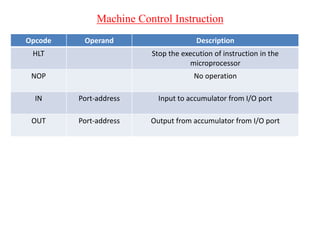
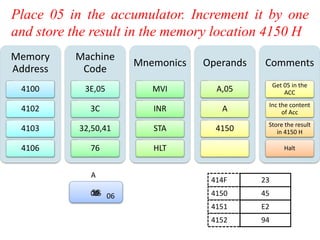

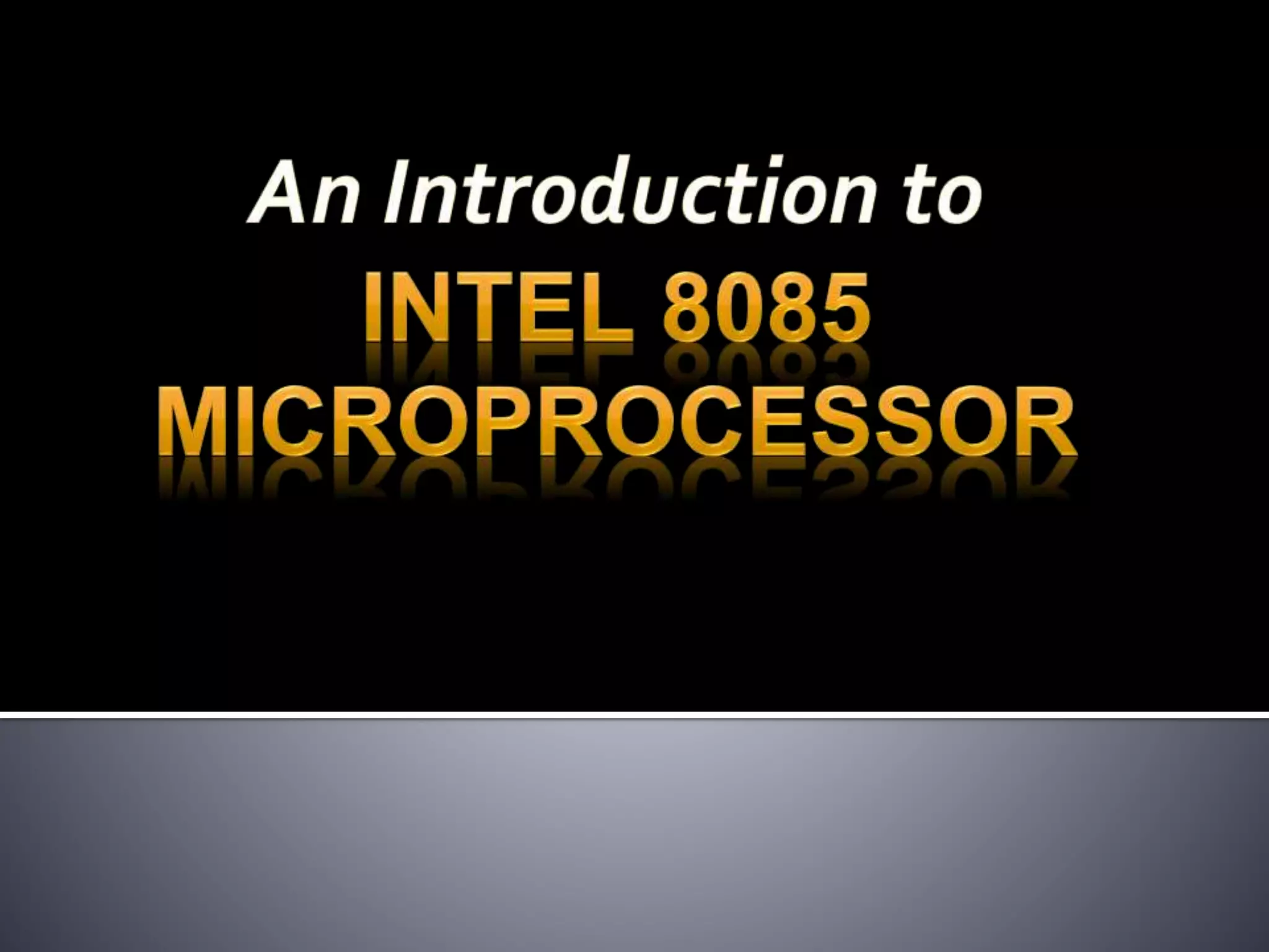
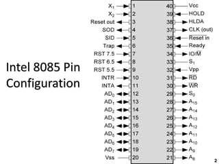
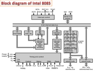
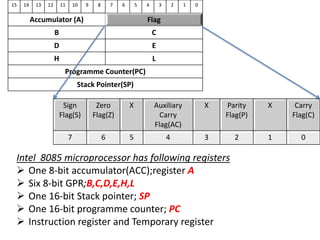
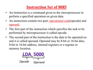
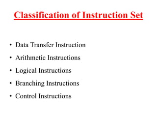
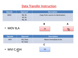
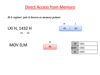
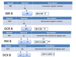
The document describes the Intel 8085 microprocessor architecture including its registers, instruction set classification, and examples of instruction types like data transfer, arithmetic, logical, and machine control instructions. It provides details on the register set which includes the accumulator, GPRs, stack pointer, program counter, and flags. It also explains the instruction format of opcode and operand and provides examples of common instructions for moving data, performing arithmetic/logical operations, branching, and I/O functions.