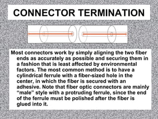
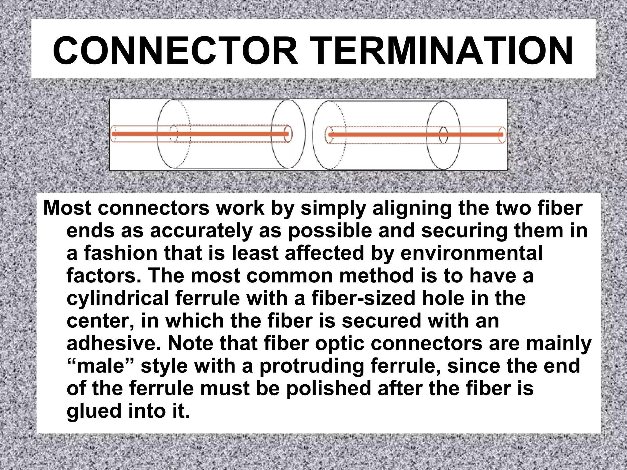
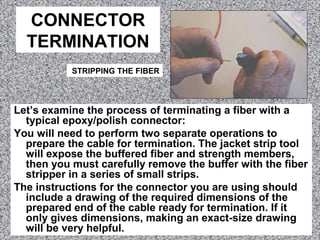
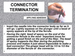
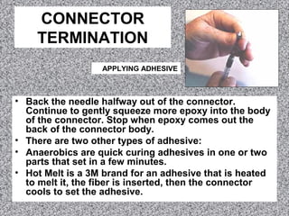
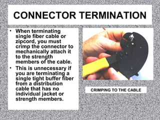
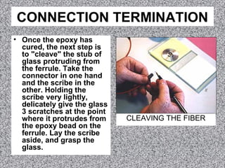
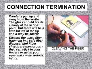
SlideShare a Scribd company logo
CONNECTOR TERMINATION
Most connectors work by simply aligning the two fiber
ends as accurately as possible and securing them in
a fashion that is least affected by environmental
factors. The most common method is to have a
cylindrical ferrule with a fiber-sized hole in the
center, in which the fiber is secured with an
adhesive. Note that fiber optic connectors are mainly
“male” style with a protruding ferrule, since the end
of the ferrule must be polished after the fiber is
glued into it.
CONNECTOR TERMINATION
• Many other connector techniques like expanded
beam, using lenses, and alignment of bare fibers like
in a splice have been tried and most have been
abandoned for all but some very specialized
applications.
• Connectors have used metal, glass, plastic and
ceramic ferrules to align the fibers accurately, but
ceramic seem to be the best choice. It is the most
environmentally stable material, closely matching
the expansion coefficient of glass fibers. It is easy to
bond to glass fiber with epoxy glues, and its
hardness is perfect for a quick polish of the fiber. As
volume has increased, ceramic costs have become
the lowest cost material for connector ferrules.
CONNECTOR TERMINATION
• Fiber optic connectors
can have several
different ferrule shapes
or finishes, usually
referred to as polishes.
Early connectors,
because they did not
have keyed ferrules and
could rotate in mating
adapters, always had an
air gap between the
connectors to prevent
them rotating and
grinding scratches into
the ends of the fibers.
CONNECTOR TERMINATION
• The air gap between the
fibers causes a reflection
when the light encounters
the change in refractive
index from the glass fiber
to the air in the gap. This
reflection is called back
reflection or optical return
loss, and can be a problem
in laser based systems.
Connectors use a number
of polishing techniques to
insure physical contact of
the fiber ends to minimize
back reflection.
CONNECTOR TERMINATION
Beginning with the ST and FC which
had keyed ferrules, the connectors
were designed to contact tightly,
what we now call physical contact
(PC) connectors. Reducing the air
gap reduced the loss and back
reflection (very important to
laser-based singlemode systems ),
since light has a loss of about 5%
(~0.25 dB) at each air gap and light
is reflected back up the fiber.
While air gap connectors usually
had losses of 0.5 dB or more and
return loss of 20 dB, PC
connectors had typical losses of
0.3 dB and a return loss of 30 to 40
dB.
CONNECTOR TERMINATION
Soon thereafter, it was determined that
making the connector ferrules
convex would produce an even
better connection. The convex ferrule
guaranteed the fiber cores were in
contact. Losses were under 0.3dB
and return loss 40 dB or better.
The final solution for singlemode
systems extremely sensitive to
reflections, like CATV or high bitrate
telco links, was to angle the end of
the ferrule 8 degrees to create what
we call an APC or angled PC
connector. Then any reflected light is
at an angle that is absorbed in the
cladding of the fiber.
CONNECTOR TERMINATION
• Epoxy/Polish: Most connectors are the simple
“epoxy/polish” type where the fiber is glued into the
connector with epoxy and the ferrule end polished
with special polishing film. These provide the most
reliable connection, lowest losses and lowest costs,
especially if you are doing a lot of connectors. The
epoxy can be allowed to set overnight or cured in an
inexpensive oven in only a few minutes.
• Quick Setting Adhesives: These connectors use a
quick setting adhesive with a curing agent to replace
the epoxy.
CONNECTOR TERMINATION
• “Hot Melt”: This is a 3M trade name for a connector
that already has the epoxy (actually a heat set glue)
inside the connector. You insert the connector in a
special oven. In a few minutes, the glue is melted, so
you remove the connector, insert the fiber, let it cool
and it is ready to polish.
• Crimp/Polish: Rather than glue the fiber in the
connector, these connectors use a crimp on the fiber
to hold it in. Expect to trade higher losses for the
faster termination speed.
• Crimp/cleave connectors only cleave the fiber for
termination - no polishing is required. Losses are
higher as a result.
CONNECTOR TERMINATION
• Prepolished/splice: Many manufacturers offer
connectors that have a short stub fiber already
epoxied into the ferrule and polished perfectly, so
you just cleave a fiber and insert it like a splice.
These connectors are very costly, you have to make
a good cleave to make them low loss, and, even if
you do everything correctly, you loss will be higher,
because you have a connector loss plus two splice
losses at every connection. Finally, they require
good training and typically have lower yield in
termination.
CONNECTOR
TERMINATION
Let’s examine the process of terminating a fiber with a
typical epoxy/polish connector:
You will need to perform two separate operations to
prepare the cable for termination. The jacket strip tool
will expose the buffered fiber and strength members,
then you must carefully remove the buffer with the fiber
stripper in a series of small strips.
The instructions for the connector you are using should
include a drawing of the required dimensions of the
prepared end of the cable ready for termination. If it
only gives dimensions, making an exact-size drawing
will be very helpful.
STRIPPING THE FIBER
CONNECTOR
TERMINATION
• Insert the needle into the connector body as far as it
will go. Lightly squeeze on the plunger until a bead of
epoxy appears at the tip of the ferrule.
• Having the right bead of epoxy on the end of the
connector ferrule is the most important issue for
getting a good finish on the end of the fiber. The bead
of epoxy supports the fiber during the polishing
process and makes it just about impossible to make a
bad connector! The proper bead will be 1/3 to 1/2 the
diameter of the ferrule of the connector.
•
APPLYING ADHESIVE
CONNECTOR
TERMINATION
• Back the needle halfway out of the connector.
Continue to gently squeeze more epoxy into the body
of the connector. Stop when epoxy comes out the
back of the connector body.
• There are two other types of adhesive:
• Anaerobics are quick curing adhesives in one or two
parts that set in a few minutes.
• Hot Melt is a 3M brand for an adhesive that is heated
to melt it, the fiber is inserted, then the connector
cools to set the adhesive.
APPLYING ADHESIVE
CONNECTOR TERMINATION
• When terminating
single fiber cable or
zipcord, you must
crimp the connector to
mechanically attach it
to the strength
members of the cable.
• This is unnecessary if
you are terminating a
single tight buffer fiber
from a distribution
cable that has no
individual jacket or
strength members.
CRIMPING TO THE CABLE
CONNECTION TERMINATION
• Once the epoxy has
cured, the next step is
to "cleave" the stub of
glass protruding from
the ferrule. Take the
connector in one hand
and the scribe in the
other. Holding the
scribe very lightly,
delicately give the glass
3 scratches at the point
where it protrudes from
the epoxy bead on the
ferrule. Lay the scribe
aside, and grasp the
glass.
CLEAVING THE FIBER
CONNECTION TERMINATION
• Carefully pull up and
away from the scribe.
The glass should break
cleanly at the scribe
point, but there will be a
little bit left at the tip
and it may be sharp!
• Discard the glass fiber
fragment in a safe fiber
disposal bin! Fiber
shards are dangerous -
they can stick in your
fingers or get in your
eyes and cause serious
injury.
CLEAVING THE FIBER
CONNECTOR TERMINATION
• "AIr Polish” the fiber stub first
with 12 micron film, holding it
as shown. Polish the tip
lightly for 10 to 20 seconds.
Notice the change in sound
(quieter) as the burr gets filed
down and the epoxy bead is
removed. Remember to brush
the tip lightly and do not
overpolish. Visually inspect
the tip. There should be some
epoxy left-just a thin film, and
the glass itself will be not be
smooth to the touch.
• The next polish step will
remove the remaining epoxy
and the protruding glass fiber.
AIR POLISHING
CONNECTOR TERMINATION
• Apply sheets of 3 and 0.3
micron lapping film to the
polishing plate or pad. If you
are polishing PC (physical
contact - or convex) ferrules,
use a rubber pad between the
polishing film and the plate.
• Always hold the polishing puck
up in your hand and then insert
the connector. Gently place the
puck with the connector in it
on the 3 micron film which is
on the polishing plate.
Remember the tip is a
protruding glass end which
can be easily damaged.
POLISHING
CONNECTOR TERMINATION
Very lightly make 4 or 5 figure eights as
you polish the tip. You'll actually feel
a smoothing of the surface as the
epoxy scrapes off and the ceramic
surface of the ferrule meets the
surface of the abrasive. Do not
overpolish the tip. Wipe the ferrule
tip before the final polish.
Very gently lay the puck on the 0.3
micron film. With almost no
pressure, make about six figure eight
strokes. Remove the tip from the
puck, and clean it with an alcohol-
soaked lint-free pad. The connection
is now complete, ready for visual
inspection of the tip.
POLISHING
CONNECTION TERMINATION
• At this point, inspect the
polished end of the ferrule with
the microscope to see that the
epoxy is completely removed
and that the tip is smooth and
free of scratches.
• There are many inspection
microscopes available with
magnifications of 100X to 400X.
Higher magnification may not
be better, as it tends to make
you more critical of scratches
and imperfections. Lower
magnifications work just fine.
MICROSCOPE
INSPECTION
CONNECTION TERMINATION
A direct view at 100 times
magnification should look like
this: The bright dot in the
center is the core of the fiber
and the darker annular ring is
the cladding. On this
connector, notice the dark area
to the left of the core, in the
cladding. This appears to be a
small crack in the fiber that
only affects the cladding, not
the core, so it is not a problem.
If the crack had been in the
core, we would not have seen a
round dot for the illuminated
core.
DIRECT
WITH CORE
ILLUMINATED
CONNECTION TERMINATION
You should also look at the tip
under the microscope at an
angle if this is possible with
the microscope you are using.
The angular view will
highlight any surface
irregularities better than the
head on view. It may look like
this: Now you can see some
small amount of epoxy still on
the end of the ferrule, which
shows up as the dark, uneven
ring around the fiber (the ring
is caused by the convex end of
the PC ferrule.)
ANGLE VIEW
CONNECTION TERMINATION
You can also see the dark area to
the left of the fiber, which is the
small crack we saw on the direct
view, but is more obvious here.
The core should be nice and
smooth, an even gray color, with
no big scratches. If you see
large scratches, go back to the
0.3 micron film and use the
polishing puck to very lightly
give 1 or 2 more figure eights to
remove them. The film of epoxy
can be removed by polishing on
the same film on the rubber
polishing pad, which polishes the
entire convex PC ferrule.
ANGLE VIEW
CONNECTION TERMINATION
Most manufacturers now offer
connectors that have a short
stub fiber already epoxied
into the ferrule and polished
perfectly, so you just cleave
a fiber and insert it like a
splice.
While this technique makes
termination faster, it has
several downsides. First it is
very costly, five to ten times
as much as an epoxy/polish
type. Second, you have to
make a good cleave to make
them low loss, and that is
not easy.
POLISHED SPLICE
CONNECTION TERMINATION
Third, even if you do everything
correctly, your loss will be
higher, because you have a
connector loss plus two
splice losses at every
connection. Finally, they
generally have lower yield in
termination.
These connectors may be good
for quick termination or
restoration, but are probably
not the lowest cost solution.
POLISHED SPLICE
CONNECTION TERMINATION
Prepolished connectors
require a good cleave
on the fiber to get
proper termination and
you must fully insert
the fiber in the
connector to make a
good splice. Using a
visible fault locator (a
bright red laser coupled
into the fiber) allows
you to see the “loss” in
the connector and work
the fiber position to get
a good termination.

More Related Content

What's hot

Optical fiber connectors
Optical fiber connectorsOptical fiber connectors
Optical fiber connectors
Jiten Thapa
 
250um loose tube vs. 900um tight buffered fiber
250um loose tube vs. 900um tight buffered fiber250um loose tube vs. 900um tight buffered fiber
250um loose tube vs. 900um tight buffered fiber
Angelina Li
 
Training Presentation Bob 09 17 09 Revised
Training Presentation Bob 09 17 09 RevisedTraining Presentation Bob 09 17 09 Revised
Training Presentation Bob 09 17 09 Revised
bdiehl
 
Fiber Optics _The Cell Site
Fiber Optics _The Cell SiteFiber Optics _The Cell Site
Fiber Optics _The Cell SiteTed Pappas
 
Fiber optics theory training
Fiber optics theory trainingFiber optics theory training
Fiber optics theory training
Colby Graves
 
OFC Puling
OFC PulingOFC Puling
OFC Puling
Bala V
 
Low-Bend Fiber Technology
Low-Bend Fiber TechnologyLow-Bend Fiber Technology
Low-Bend Fiber Technologyineltec 2011
 
Introduction to Fiber Breakout Cable
Introduction to Fiber Breakout CableIntroduction to Fiber Breakout Cable
Introduction to Fiber Breakout Cable
Jo Wang
 
Coaxial cable and its types
Coaxial cable and its typesCoaxial cable and its types
Coaxial cable and its types
Adeel Khurram
 
Fiber Optic Connectors, Designs, Applications, Choices
Fiber Optic Connectors, Designs, Applications, Choices Fiber Optic Connectors, Designs, Applications, Choices
Fiber Optic Connectors, Designs, Applications, Choices
LizGoldsmith
 
About fiber optic
About fiber opticAbout fiber optic
About fiber optic
a0109
 
Fiber Optical cable brochure-QianXin
Fiber Optical cable brochure-QianXinFiber Optical cable brochure-QianXin
Fiber Optical cable brochure-QianXinMarcio Maia Figueira
 
Fiber Optics - Conference
Fiber Optics - ConferenceFiber Optics - Conference
Fiber Optics - Conference
Alex TX
 
Coaxial cable installation
Coaxial cable installationCoaxial cable installation
Coaxial cable installationVinod Jadhav
 
Communication with fiber optic technology
Communication with fiber optic technologyCommunication with fiber optic technology
Communication with fiber optic technology
PranavKoshe
 
Coaxial cable research report by alina baber
Coaxial cable research report by alina baberCoaxial cable research report by alina baber
Coaxial cable research report by alina baber
Alina Baber
 
construction of underground cable
construction of underground cableconstruction of underground cable
construction of underground cable
Rajal Patel
 
Insertion loss: What is it?
Insertion loss:  What is it?Insertion loss:  What is it?
Insertion loss: What is it?
OptoTest
 

What's hot (20)

Optical fiber connectors
Optical fiber connectorsOptical fiber connectors
Optical fiber connectors
 
250um loose tube vs. 900um tight buffered fiber
250um loose tube vs. 900um tight buffered fiber250um loose tube vs. 900um tight buffered fiber
250um loose tube vs. 900um tight buffered fiber
 
Training Presentation Bob 09 17 09 Revised
Training Presentation Bob 09 17 09 RevisedTraining Presentation Bob 09 17 09 Revised
Training Presentation Bob 09 17 09 Revised
 
Fiber Optics _The Cell Site
Fiber Optics _The Cell SiteFiber Optics _The Cell Site
Fiber Optics _The Cell Site
 
Fiber optics ppp
Fiber optics pppFiber optics ppp
Fiber optics ppp
 
Fiber optics theory training
Fiber optics theory trainingFiber optics theory training
Fiber optics theory training
 
OFC Puling
OFC PulingOFC Puling
OFC Puling
 
Low-Bend Fiber Technology
Low-Bend Fiber TechnologyLow-Bend Fiber Technology
Low-Bend Fiber Technology
 
Introduction to Fiber Breakout Cable
Introduction to Fiber Breakout CableIntroduction to Fiber Breakout Cable
Introduction to Fiber Breakout Cable
 
Coaxial cable and its types
Coaxial cable and its typesCoaxial cable and its types
Coaxial cable and its types
 
Fiber Optic Connectors, Designs, Applications, Choices
Fiber Optic Connectors, Designs, Applications, Choices Fiber Optic Connectors, Designs, Applications, Choices
Fiber Optic Connectors, Designs, Applications, Choices
 
About fiber optic
About fiber opticAbout fiber optic
About fiber optic
 
Fiber Optical cable brochure-QianXin
Fiber Optical cable brochure-QianXinFiber Optical cable brochure-QianXin
Fiber Optical cable brochure-QianXin
 
Fiber Optics - Conference
Fiber Optics - ConferenceFiber Optics - Conference
Fiber Optics - Conference
 
Coaxial cable installation
Coaxial cable installationCoaxial cable installation
Coaxial cable installation
 
Communication with fiber optic technology
Communication with fiber optic technologyCommunication with fiber optic technology
Communication with fiber optic technology
 
Fiber
FiberFiber
Fiber
 
Coaxial cable research report by alina baber
Coaxial cable research report by alina baberCoaxial cable research report by alina baber
Coaxial cable research report by alina baber
 
construction of underground cable
construction of underground cableconstruction of underground cable
construction of underground cable
 
Insertion loss: What is it?
Insertion loss:  What is it?Insertion loss:  What is it?
Insertion loss: What is it?
 

Viewers also liked

WebDeveloper.doc.docx
WebDeveloper.doc.docxWebDeveloper.doc.docx
WebDeveloper.doc.docxpramodknj67
 
Mep contractors in doha, qatar
Mep contractors in doha, qatarMep contractors in doha, qatar
Mep contractors in doha, qatar
qatpedia
 
Mf0016 treasury management
Mf0016 treasury managementMf0016 treasury management
Mf0016 treasury management
consult4solutions
 
Mb0052 strategic management and business policy
Mb0052 strategic management and business policyMb0052 strategic management and business policy
Mb0052 strategic management and business policy
consult4solutions
 
summary report Front page 2nd year Michi
summary report Front page 2nd year Michisummary report Front page 2nd year Michi
summary report Front page 2nd year MichiDawa Sherpa
 
Nguyenlythietkekientrucnhao 150615171035-lva1-app6892
Nguyenlythietkekientrucnhao 150615171035-lva1-app6892Nguyenlythietkekientrucnhao 150615171035-lva1-app6892
Nguyenlythietkekientrucnhao 150615171035-lva1-app6892
Tuấn Vinh Huỳnh
 
Tinh toan ket_cau_thep(_nguyen_van_yen)_
Tinh toan ket_cau_thep(_nguyen_van_yen)_Tinh toan ket_cau_thep(_nguyen_van_yen)_
Tinh toan ket_cau_thep(_nguyen_van_yen)_
Tuấn Vinh Huỳnh
 
организация летнего отдыха
организация летнего отдыхаорганизация летнего отдыха
организация летнего отдыха
arzmary
 
Shallows
ShallowsShallows
Shallows
sarahlouise12
 
Zorunlu trafik sigortasi fiyatları
Zorunlu trafik sigortasi fiyatlarıZorunlu trafik sigortasi fiyatları
Zorunlu trafik sigortasi fiyatları
Sigorta Bilgileri
 
Geohydrology ii (1)
Geohydrology ii (1)Geohydrology ii (1)
Geohydrology ii (1)
Amro Elfeki
 
Asignacion 5 termodinamica
Asignacion 5 termodinamicaAsignacion 5 termodinamica
Asignacion 5 termodinamica
cesarherrera1212
 
Impacts du changement climatique
Impacts du changement climatiqueImpacts du changement climatique
Impacts du changement climatique
Benoît Browaeys
 
FirelightProjectExperience
FirelightProjectExperienceFirelightProjectExperience
FirelightProjectExperienceTabitha Steager
 
Summary of Learning
Summary of Learning Summary of Learning
Summary of Learning
Sheri Schlosser
 
Experience mapping presentation
Experience mapping presentationExperience mapping presentation
Experience mapping presentation
James Hall
 
Cpd ch9 engage deeply
Cpd ch9 engage deeplyCpd ch9 engage deeply
Cpd ch9 engage deeply
RONAK SUTARIYA
 
Ib0013 export import management
Ib0013 export import managementIb0013 export import management
Ib0013 export import management
consult4solutions
 
Professional Certifications and Achievements
Professional Certifications and AchievementsProfessional Certifications and Achievements
Professional Certifications and AchievementsAbhishek Verma
 

Viewers also liked (20)

WebDeveloper.doc.docx
WebDeveloper.doc.docxWebDeveloper.doc.docx
WebDeveloper.doc.docx
 
Mep contractors in doha, qatar
Mep contractors in doha, qatarMep contractors in doha, qatar
Mep contractors in doha, qatar
 
Mf0016 treasury management
Mf0016 treasury managementMf0016 treasury management
Mf0016 treasury management
 
Mb0052 strategic management and business policy
Mb0052 strategic management and business policyMb0052 strategic management and business policy
Mb0052 strategic management and business policy
 
summary report Front page 2nd year Michi
summary report Front page 2nd year Michisummary report Front page 2nd year Michi
summary report Front page 2nd year Michi
 
第七课 -电脑和网络
第七课 -电脑和网络 第七课 -电脑和网络
第七课 -电脑和网络
 
Nguyenlythietkekientrucnhao 150615171035-lva1-app6892
Nguyenlythietkekientrucnhao 150615171035-lva1-app6892Nguyenlythietkekientrucnhao 150615171035-lva1-app6892
Nguyenlythietkekientrucnhao 150615171035-lva1-app6892
 
Tinh toan ket_cau_thep(_nguyen_van_yen)_
Tinh toan ket_cau_thep(_nguyen_van_yen)_Tinh toan ket_cau_thep(_nguyen_van_yen)_
Tinh toan ket_cau_thep(_nguyen_van_yen)_
 
организация летнего отдыха
организация летнего отдыхаорганизация летнего отдыха
организация летнего отдыха
 
Shallows
ShallowsShallows
Shallows
 
Zorunlu trafik sigortasi fiyatları
Zorunlu trafik sigortasi fiyatlarıZorunlu trafik sigortasi fiyatları
Zorunlu trafik sigortasi fiyatları
 
Geohydrology ii (1)
Geohydrology ii (1)Geohydrology ii (1)
Geohydrology ii (1)
 
Asignacion 5 termodinamica
Asignacion 5 termodinamicaAsignacion 5 termodinamica
Asignacion 5 termodinamica
 
Impacts du changement climatique
Impacts du changement climatiqueImpacts du changement climatique
Impacts du changement climatique
 
FirelightProjectExperience
FirelightProjectExperienceFirelightProjectExperience
FirelightProjectExperience
 
Summary of Learning
Summary of Learning Summary of Learning
Summary of Learning
 
Experience mapping presentation
Experience mapping presentationExperience mapping presentation
Experience mapping presentation
 
Cpd ch9 engage deeply
Cpd ch9 engage deeplyCpd ch9 engage deeply
Cpd ch9 engage deeply
 
Ib0013 export import management
Ib0013 export import managementIb0013 export import management
Ib0013 export import management
 
Professional Certifications and Achievements
Professional Certifications and AchievementsProfessional Certifications and Achievements
Professional Certifications and Achievements
 

Similar to Fiber optics 2-5

Fiber optics 2-6
Fiber optics 2-6Fiber optics 2-6
Fiber optics 2-6
grantlerc
 
A guide for fiber optic terminations, beyondtech
A guide for fiber optic terminations, beyondtechA guide for fiber optic terminations, beyondtech
A guide for fiber optic terminations, beyondtech
BEYONDTECH
 
Shoulder porcelain
Shoulder porcelainShoulder porcelain
Shoulder porcelain
Faezeh Atri
 
Optical Fiber connectors
Optical Fiber connectorsOptical Fiber connectors
Optical Fiber connectors
Ahmed Amer
 
How to Install a Fiber Optic Connector?
How to Install a Fiber Optic Connector?How to Install a Fiber Optic Connector?
How to Install a Fiber Optic Connector?
Jo Wang
 
Silicon solar cell design
Silicon solar cell designSilicon solar cell design
Silicon solar cell design
Gomathy Sengottaiyan
 
Birkett Cable Jointing Kits - Jointers Instruction
Birkett Cable Jointing Kits - Jointers InstructionBirkett Cable Jointing Kits - Jointers Instruction
Birkett Cable Jointing Kits - Jointers Instruction
Thorne & Derrick International
 
Impression Techniques in Fixed partial denture
Impression Techniques in Fixed partial dentureImpression Techniques in Fixed partial denture
Impression Techniques in Fixed partial denture
Dr.Richa Sahai
 
OFC PPTs fiber materials, fabrication and signal destortion.pptx
OFC PPTs fiber materials, fabrication and signal destortion.pptxOFC PPTs fiber materials, fabrication and signal destortion.pptx
OFC PPTs fiber materials, fabrication and signal destortion.pptx
2BA19EC113Vijay
 
holmes_presentation
holmes_presentationholmes_presentation
holmes_presentationRigel1951
 
Ofc day 4
Ofc day 4Ofc day 4
Ofc day 4
Gaganpreet Singh
 
Losses ofc
Losses ofcLosses ofc
Losses ofc
Dinesh Kumar
 
Basic Electrical Splicing
Basic Electrical SplicingBasic Electrical Splicing
Basic Electrical Splicing
Raymar Baquilar
 
howtospliceelectricalwires-160915075216.pdf
howtospliceelectricalwires-160915075216.pdfhowtospliceelectricalwires-160915075216.pdf
howtospliceelectricalwires-160915075216.pdf
JhoanaTamondong
 
8th Sem Subject OFC 2nd chapter notes by Lohith kumar 11GUEE6018
8th Sem Subject OFC 2nd chapter notes by Lohith kumar 11GUEE60188th Sem Subject OFC 2nd chapter notes by Lohith kumar 11GUEE6018
8th Sem Subject OFC 2nd chapter notes by Lohith kumar 11GUEE6018
UVCE
 
Fiber Optic Termination
Fiber Optic TerminationFiber Optic Termination
Fiber Optic Termination
sulaim_qais
 
Bicsi news best-practices
Bicsi news best-practicesBicsi news best-practices
Bicsi news best-practices
irshadalam72
 
Catalogue ls vina tnhh kim_xuan
Catalogue ls vina tnhh kim_xuanCatalogue ls vina tnhh kim_xuan
Catalogue ls vina tnhh kim_xuan
Ngan TNHH
 
Fiber Optic Cable Installation and Handling Instructions
Fiber Optic Cable Installation and Handling InstructionsFiber Optic Cable Installation and Handling Instructions
Fiber Optic Cable Installation and Handling Instructions
The LED Studio
 
VLSI process integration
VLSI process integrationVLSI process integration
VLSI process integration
neha sharma
 

Similar to Fiber optics 2-5 (20)

Fiber optics 2-6
Fiber optics 2-6Fiber optics 2-6
Fiber optics 2-6
 
A guide for fiber optic terminations, beyondtech
A guide for fiber optic terminations, beyondtechA guide for fiber optic terminations, beyondtech
A guide for fiber optic terminations, beyondtech
 
Shoulder porcelain
Shoulder porcelainShoulder porcelain
Shoulder porcelain
 
Optical Fiber connectors
Optical Fiber connectorsOptical Fiber connectors
Optical Fiber connectors
 
How to Install a Fiber Optic Connector?
How to Install a Fiber Optic Connector?How to Install a Fiber Optic Connector?
How to Install a Fiber Optic Connector?
 
Silicon solar cell design
Silicon solar cell designSilicon solar cell design
Silicon solar cell design
 
Birkett Cable Jointing Kits - Jointers Instruction
Birkett Cable Jointing Kits - Jointers InstructionBirkett Cable Jointing Kits - Jointers Instruction
Birkett Cable Jointing Kits - Jointers Instruction
 
Impression Techniques in Fixed partial denture
Impression Techniques in Fixed partial dentureImpression Techniques in Fixed partial denture
Impression Techniques in Fixed partial denture
 
OFC PPTs fiber materials, fabrication and signal destortion.pptx
OFC PPTs fiber materials, fabrication and signal destortion.pptxOFC PPTs fiber materials, fabrication and signal destortion.pptx
OFC PPTs fiber materials, fabrication and signal destortion.pptx
 
holmes_presentation
holmes_presentationholmes_presentation
holmes_presentation
 
Ofc day 4
Ofc day 4Ofc day 4
Ofc day 4
 
Losses ofc
Losses ofcLosses ofc
Losses ofc
 
Basic Electrical Splicing
Basic Electrical SplicingBasic Electrical Splicing
Basic Electrical Splicing
 
howtospliceelectricalwires-160915075216.pdf
howtospliceelectricalwires-160915075216.pdfhowtospliceelectricalwires-160915075216.pdf
howtospliceelectricalwires-160915075216.pdf
 
8th Sem Subject OFC 2nd chapter notes by Lohith kumar 11GUEE6018
8th Sem Subject OFC 2nd chapter notes by Lohith kumar 11GUEE60188th Sem Subject OFC 2nd chapter notes by Lohith kumar 11GUEE6018
8th Sem Subject OFC 2nd chapter notes by Lohith kumar 11GUEE6018
 
Fiber Optic Termination
Fiber Optic TerminationFiber Optic Termination
Fiber Optic Termination
 
Bicsi news best-practices
Bicsi news best-practicesBicsi news best-practices
Bicsi news best-practices
 
Catalogue ls vina tnhh kim_xuan
Catalogue ls vina tnhh kim_xuanCatalogue ls vina tnhh kim_xuan
Catalogue ls vina tnhh kim_xuan
 
Fiber Optic Cable Installation and Handling Instructions
Fiber Optic Cable Installation and Handling InstructionsFiber Optic Cable Installation and Handling Instructions
Fiber Optic Cable Installation and Handling Instructions
 
VLSI process integration
VLSI process integrationVLSI process integration
VLSI process integration
 

More from grantlerc

Fire alarm 3-f-single_and_multiple-station_alarms_and_household_fire_alarm_sy...
Fire alarm 3-f-single_and_multiple-station_alarms_and_household_fire_alarm_sy...Fire alarm 3-f-single_and_multiple-station_alarms_and_household_fire_alarm_sy...
Fire alarm 3-f-single_and_multiple-station_alarms_and_household_fire_alarm_sy...
grantlerc
 
Fire alarm 3-e-public_emergency_alarm_reporting_systems
Fire alarm 3-e-public_emergency_alarm_reporting_systemsFire alarm 3-e-public_emergency_alarm_reporting_systems
Fire alarm 3-e-public_emergency_alarm_reporting_systems
grantlerc
 
Fire alarm 3-d-supervising_station_alarm_system
Fire alarm 3-d-supervising_station_alarm_systemFire alarm 3-d-supervising_station_alarm_system
Fire alarm 3-d-supervising_station_alarm_system
grantlerc
 
Fire alarm 3-b-protected_premises_fire_alarm_system
Fire alarm 3-b-protected_premises_fire_alarm_systemFire alarm 3-b-protected_premises_fire_alarm_system
Fire alarm 3-b-protected_premises_fire_alarm_system
grantlerc
 
Fire alarm 3-a-emergency_control_functions
Fire alarm 3-a-emergency_control_functionsFire alarm 3-a-emergency_control_functions
Fire alarm 3-a-emergency_control_functions
grantlerc
 
Fire alarm basics 1-6
Fire alarm basics 1-6Fire alarm basics 1-6
Fire alarm basics 1-6
grantlerc
 
Fire alarm basics 1-5
Fire alarm basics 1-5Fire alarm basics 1-5
Fire alarm basics 1-5
grantlerc
 
Fire alarm 2_f_manual supervisory
Fire alarm 2_f_manual supervisoryFire alarm 2_f_manual supervisory
Fire alarm 2_f_manual supervisory
grantlerc
 
Fire alarm 2_e_combination
Fire alarm 2_e_combinationFire alarm 2_e_combination
Fire alarm 2_e_combination
grantlerc
 
Fire alarm 2_d_radiant energy detectors
Fire alarm 2_d_radiant energy detectorsFire alarm 2_d_radiant energy detectors
Fire alarm 2_d_radiant energy detectors
grantlerc
 
Fire alarm 2_c_smoke detectors
Fire alarm 2_c_smoke detectorsFire alarm 2_c_smoke detectors
Fire alarm 2_c_smoke detectors
grantlerc
 
Fire alarm 2_b_heat detectors
Fire alarm 2_b_heat detectorsFire alarm 2_b_heat detectors
Fire alarm 2_b_heat detectors
grantlerc
 
Fire alarm 2_a_initiation basics
Fire alarm 2_a_initiation basicsFire alarm 2_a_initiation basics
Fire alarm 2_a_initiation basics
grantlerc
 
Fire basics 1-4-risers_thru_power_supplies_08
Fire basics 1-4-risers_thru_power_supplies_08Fire basics 1-4-risers_thru_power_supplies_08
Fire basics 1-4-risers_thru_power_supplies_08
grantlerc
 
Fire basics 1-3-functions_to_docs_08
Fire basics 1-3-functions_to_docs_08Fire basics 1-3-functions_to_docs_08
Fire basics 1-3-functions_to_docs_08
grantlerc
 
Fire basics 1-2-the_nec_11
Fire basics 1-2-the_nec_11Fire basics 1-2-the_nec_11
Fire basics 1-2-the_nec_11
grantlerc
 
Fire basics 1-1-fundamentals
Fire basics 1-1-fundamentalsFire basics 1-1-fundamentals
Fire basics 1-1-fundamentals
grantlerc
 
Fiber optics 2-1
Fiber optics 2-1Fiber optics 2-1
Fiber optics 2-1
grantlerc
 
Burglar alarm basics-1
Burglar alarm basics-1Burglar alarm basics-1
Burglar alarm basics-1
grantlerc
 
Access control basics-9
Access control basics-9Access control basics-9
Access control basics-9
grantlerc
 

More from grantlerc (20)

Fire alarm 3-f-single_and_multiple-station_alarms_and_household_fire_alarm_sy...
Fire alarm 3-f-single_and_multiple-station_alarms_and_household_fire_alarm_sy...Fire alarm 3-f-single_and_multiple-station_alarms_and_household_fire_alarm_sy...
Fire alarm 3-f-single_and_multiple-station_alarms_and_household_fire_alarm_sy...
 
Fire alarm 3-e-public_emergency_alarm_reporting_systems
Fire alarm 3-e-public_emergency_alarm_reporting_systemsFire alarm 3-e-public_emergency_alarm_reporting_systems
Fire alarm 3-e-public_emergency_alarm_reporting_systems
 
Fire alarm 3-d-supervising_station_alarm_system
Fire alarm 3-d-supervising_station_alarm_systemFire alarm 3-d-supervising_station_alarm_system
Fire alarm 3-d-supervising_station_alarm_system
 
Fire alarm 3-b-protected_premises_fire_alarm_system
Fire alarm 3-b-protected_premises_fire_alarm_systemFire alarm 3-b-protected_premises_fire_alarm_system
Fire alarm 3-b-protected_premises_fire_alarm_system
 
Fire alarm 3-a-emergency_control_functions
Fire alarm 3-a-emergency_control_functionsFire alarm 3-a-emergency_control_functions
Fire alarm 3-a-emergency_control_functions
 
Fire alarm basics 1-6
Fire alarm basics 1-6Fire alarm basics 1-6
Fire alarm basics 1-6
 
Fire alarm basics 1-5
Fire alarm basics 1-5Fire alarm basics 1-5
Fire alarm basics 1-5
 
Fire alarm 2_f_manual supervisory
Fire alarm 2_f_manual supervisoryFire alarm 2_f_manual supervisory
Fire alarm 2_f_manual supervisory
 
Fire alarm 2_e_combination
Fire alarm 2_e_combinationFire alarm 2_e_combination
Fire alarm 2_e_combination
 
Fire alarm 2_d_radiant energy detectors
Fire alarm 2_d_radiant energy detectorsFire alarm 2_d_radiant energy detectors
Fire alarm 2_d_radiant energy detectors
 
Fire alarm 2_c_smoke detectors
Fire alarm 2_c_smoke detectorsFire alarm 2_c_smoke detectors
Fire alarm 2_c_smoke detectors
 
Fire alarm 2_b_heat detectors
Fire alarm 2_b_heat detectorsFire alarm 2_b_heat detectors
Fire alarm 2_b_heat detectors
 
Fire alarm 2_a_initiation basics
Fire alarm 2_a_initiation basicsFire alarm 2_a_initiation basics
Fire alarm 2_a_initiation basics
 
Fire basics 1-4-risers_thru_power_supplies_08
Fire basics 1-4-risers_thru_power_supplies_08Fire basics 1-4-risers_thru_power_supplies_08
Fire basics 1-4-risers_thru_power_supplies_08
 
Fire basics 1-3-functions_to_docs_08
Fire basics 1-3-functions_to_docs_08Fire basics 1-3-functions_to_docs_08
Fire basics 1-3-functions_to_docs_08
 
Fire basics 1-2-the_nec_11
Fire basics 1-2-the_nec_11Fire basics 1-2-the_nec_11
Fire basics 1-2-the_nec_11
 
Fire basics 1-1-fundamentals
Fire basics 1-1-fundamentalsFire basics 1-1-fundamentals
Fire basics 1-1-fundamentals
 
Fiber optics 2-1
Fiber optics 2-1Fiber optics 2-1
Fiber optics 2-1
 
Burglar alarm basics-1
Burglar alarm basics-1Burglar alarm basics-1
Burglar alarm basics-1
 
Access control basics-9
Access control basics-9Access control basics-9
Access control basics-9
 

Recently uploaded

CFD Simulation of By-pass Flow in a HRSG module by R&R Consult.pptx
CFD Simulation of By-pass Flow in a HRSG module by R&R Consult.pptxCFD Simulation of By-pass Flow in a HRSG module by R&R Consult.pptx
CFD Simulation of By-pass Flow in a HRSG module by R&R Consult.pptx
R&R Consult
 
Sachpazis:Terzaghi Bearing Capacity Estimation in simple terms with Calculati...
Sachpazis:Terzaghi Bearing Capacity Estimation in simple terms with Calculati...Sachpazis:Terzaghi Bearing Capacity Estimation in simple terms with Calculati...
Sachpazis:Terzaghi Bearing Capacity Estimation in simple terms with Calculati...
Dr.Costas Sachpazis
 
ethical hacking in wireless-hacking1.ppt
ethical hacking in wireless-hacking1.pptethical hacking in wireless-hacking1.ppt
ethical hacking in wireless-hacking1.ppt
Jayaprasanna4
 
在线办理(ANU毕业证书)澳洲国立大学毕业证录取通知书一模一样
在线办理(ANU毕业证书)澳洲国立大学毕业证录取通知书一模一样在线办理(ANU毕业证书)澳洲国立大学毕业证录取通知书一模一样
在线办理(ANU毕业证书)澳洲国立大学毕业证录取通知书一模一样
obonagu
 
Hybrid optimization of pumped hydro system and solar- Engr. Abdul-Azeez.pdf
Hybrid optimization of pumped hydro system and solar- Engr. Abdul-Azeez.pdfHybrid optimization of pumped hydro system and solar- Engr. Abdul-Azeez.pdf
Hybrid optimization of pumped hydro system and solar- Engr. Abdul-Azeez.pdf
fxintegritypublishin
 
block diagram and signal flow graph representation
block diagram and signal flow graph representationblock diagram and signal flow graph representation
block diagram and signal flow graph representation
Divya Somashekar
 
CME397 Surface Engineering- Professional Elective
CME397 Surface Engineering- Professional ElectiveCME397 Surface Engineering- Professional Elective
CME397 Surface Engineering- Professional Elective
karthi keyan
 
addressing modes in computer architecture
addressing modes  in computer architectureaddressing modes  in computer architecture
addressing modes in computer architecture
ShahidSultan24
 
Automobile Management System Project Report.pdf
Automobile Management System Project Report.pdfAutomobile Management System Project Report.pdf
Automobile Management System Project Report.pdf
Kamal Acharya
 
ASME IX(9) 2007 Full Version .pdf
ASME IX(9)  2007 Full Version       .pdfASME IX(9)  2007 Full Version       .pdf
ASME IX(9) 2007 Full Version .pdf
AhmedHussein950959
 
Quality defects in TMT Bars, Possible causes and Potential Solutions.
Quality defects in TMT Bars, Possible causes and Potential Solutions.Quality defects in TMT Bars, Possible causes and Potential Solutions.
Quality defects in TMT Bars, Possible causes and Potential Solutions.
PrashantGoswami42
 
Halogenation process of chemical process industries
Halogenation process of chemical process industriesHalogenation process of chemical process industries
Halogenation process of chemical process industries
MuhammadTufail242431
 
The role of big data in decision making.
The role of big data in decision making.The role of big data in decision making.
The role of big data in decision making.
ankuprajapati0525
 
power quality voltage fluctuation UNIT - I.pptx
power quality voltage fluctuation UNIT - I.pptxpower quality voltage fluctuation UNIT - I.pptx
power quality voltage fluctuation UNIT - I.pptx
ViniHema
 
NO1 Uk best vashikaran specialist in delhi vashikaran baba near me online vas...
NO1 Uk best vashikaran specialist in delhi vashikaran baba near me online vas...NO1 Uk best vashikaran specialist in delhi vashikaran baba near me online vas...
NO1 Uk best vashikaran specialist in delhi vashikaran baba near me online vas...
Amil Baba Dawood bangali
 
HYDROPOWER - Hydroelectric power generation
HYDROPOWER - Hydroelectric power generationHYDROPOWER - Hydroelectric power generation
HYDROPOWER - Hydroelectric power generation
Robbie Edward Sayers
 
Forklift Classes Overview by Intella Parts
Forklift Classes Overview by Intella PartsForklift Classes Overview by Intella Parts
Forklift Classes Overview by Intella Parts
Intella Parts
 
Student information management system project report ii.pdf
Student information management system project report ii.pdfStudent information management system project report ii.pdf
Student information management system project report ii.pdf
Kamal Acharya
 
Cosmetic shop management system project report.pdf
Cosmetic shop management system project report.pdfCosmetic shop management system project report.pdf
Cosmetic shop management system project report.pdf
Kamal Acharya
 
Planning Of Procurement o different goods and services
Planning Of Procurement o different goods and servicesPlanning Of Procurement o different goods and services
Planning Of Procurement o different goods and services
JoytuBarua2
 

Recently uploaded (20)

CFD Simulation of By-pass Flow in a HRSG module by R&R Consult.pptx
CFD Simulation of By-pass Flow in a HRSG module by R&R Consult.pptxCFD Simulation of By-pass Flow in a HRSG module by R&R Consult.pptx
CFD Simulation of By-pass Flow in a HRSG module by R&R Consult.pptx
 
Sachpazis:Terzaghi Bearing Capacity Estimation in simple terms with Calculati...
Sachpazis:Terzaghi Bearing Capacity Estimation in simple terms with Calculati...Sachpazis:Terzaghi Bearing Capacity Estimation in simple terms with Calculati...
Sachpazis:Terzaghi Bearing Capacity Estimation in simple terms with Calculati...
 
ethical hacking in wireless-hacking1.ppt
ethical hacking in wireless-hacking1.pptethical hacking in wireless-hacking1.ppt
ethical hacking in wireless-hacking1.ppt
 
在线办理(ANU毕业证书)澳洲国立大学毕业证录取通知书一模一样
在线办理(ANU毕业证书)澳洲国立大学毕业证录取通知书一模一样在线办理(ANU毕业证书)澳洲国立大学毕业证录取通知书一模一样
在线办理(ANU毕业证书)澳洲国立大学毕业证录取通知书一模一样
 
Hybrid optimization of pumped hydro system and solar- Engr. Abdul-Azeez.pdf
Hybrid optimization of pumped hydro system and solar- Engr. Abdul-Azeez.pdfHybrid optimization of pumped hydro system and solar- Engr. Abdul-Azeez.pdf
Hybrid optimization of pumped hydro system and solar- Engr. Abdul-Azeez.pdf
 
block diagram and signal flow graph representation
block diagram and signal flow graph representationblock diagram and signal flow graph representation
block diagram and signal flow graph representation
 
CME397 Surface Engineering- Professional Elective
CME397 Surface Engineering- Professional ElectiveCME397 Surface Engineering- Professional Elective
CME397 Surface Engineering- Professional Elective
 
addressing modes in computer architecture
addressing modes  in computer architectureaddressing modes  in computer architecture
addressing modes in computer architecture
 
Automobile Management System Project Report.pdf
Automobile Management System Project Report.pdfAutomobile Management System Project Report.pdf
Automobile Management System Project Report.pdf
 
ASME IX(9) 2007 Full Version .pdf
ASME IX(9)  2007 Full Version       .pdfASME IX(9)  2007 Full Version       .pdf
ASME IX(9) 2007 Full Version .pdf
 
Quality defects in TMT Bars, Possible causes and Potential Solutions.
Quality defects in TMT Bars, Possible causes and Potential Solutions.Quality defects in TMT Bars, Possible causes and Potential Solutions.
Quality defects in TMT Bars, Possible causes and Potential Solutions.
 
Halogenation process of chemical process industries
Halogenation process of chemical process industriesHalogenation process of chemical process industries
Halogenation process of chemical process industries
 
The role of big data in decision making.
The role of big data in decision making.The role of big data in decision making.
The role of big data in decision making.
 
power quality voltage fluctuation UNIT - I.pptx
power quality voltage fluctuation UNIT - I.pptxpower quality voltage fluctuation UNIT - I.pptx
power quality voltage fluctuation UNIT - I.pptx
 
NO1 Uk best vashikaran specialist in delhi vashikaran baba near me online vas...
NO1 Uk best vashikaran specialist in delhi vashikaran baba near me online vas...NO1 Uk best vashikaran specialist in delhi vashikaran baba near me online vas...
NO1 Uk best vashikaran specialist in delhi vashikaran baba near me online vas...
 
HYDROPOWER - Hydroelectric power generation
HYDROPOWER - Hydroelectric power generationHYDROPOWER - Hydroelectric power generation
HYDROPOWER - Hydroelectric power generation
 
Forklift Classes Overview by Intella Parts
Forklift Classes Overview by Intella PartsForklift Classes Overview by Intella Parts
Forklift Classes Overview by Intella Parts
 
Student information management system project report ii.pdf
Student information management system project report ii.pdfStudent information management system project report ii.pdf
Student information management system project report ii.pdf
 
Cosmetic shop management system project report.pdf
Cosmetic shop management system project report.pdfCosmetic shop management system project report.pdf
Cosmetic shop management system project report.pdf
 
Planning Of Procurement o different goods and services
Planning Of Procurement o different goods and servicesPlanning Of Procurement o different goods and services
Planning Of Procurement o different goods and services
 

Fiber optics 2-5

  • 1. CONNECTOR TERMINATION Most connectors work by simply aligning the two fiber ends as accurately as possible and securing them in a fashion that is least affected by environmental factors. The most common method is to have a cylindrical ferrule with a fiber-sized hole in the center, in which the fiber is secured with an adhesive. Note that fiber optic connectors are mainly “male” style with a protruding ferrule, since the end of the ferrule must be polished after the fiber is glued into it.
  • 2. CONNECTOR TERMINATION • Many other connector techniques like expanded beam, using lenses, and alignment of bare fibers like in a splice have been tried and most have been abandoned for all but some very specialized applications. • Connectors have used metal, glass, plastic and ceramic ferrules to align the fibers accurately, but ceramic seem to be the best choice. It is the most environmentally stable material, closely matching the expansion coefficient of glass fibers. It is easy to bond to glass fiber with epoxy glues, and its hardness is perfect for a quick polish of the fiber. As volume has increased, ceramic costs have become the lowest cost material for connector ferrules.
  • 3. CONNECTOR TERMINATION • Fiber optic connectors can have several different ferrule shapes or finishes, usually referred to as polishes. Early connectors, because they did not have keyed ferrules and could rotate in mating adapters, always had an air gap between the connectors to prevent them rotating and grinding scratches into the ends of the fibers.
  • 4. CONNECTOR TERMINATION • The air gap between the fibers causes a reflection when the light encounters the change in refractive index from the glass fiber to the air in the gap. This reflection is called back reflection or optical return loss, and can be a problem in laser based systems. Connectors use a number of polishing techniques to insure physical contact of the fiber ends to minimize back reflection.
  • 5. CONNECTOR TERMINATION Beginning with the ST and FC which had keyed ferrules, the connectors were designed to contact tightly, what we now call physical contact (PC) connectors. Reducing the air gap reduced the loss and back reflection (very important to laser-based singlemode systems ), since light has a loss of about 5% (~0.25 dB) at each air gap and light is reflected back up the fiber. While air gap connectors usually had losses of 0.5 dB or more and return loss of 20 dB, PC connectors had typical losses of 0.3 dB and a return loss of 30 to 40 dB.
  • 6. CONNECTOR TERMINATION Soon thereafter, it was determined that making the connector ferrules convex would produce an even better connection. The convex ferrule guaranteed the fiber cores were in contact. Losses were under 0.3dB and return loss 40 dB or better. The final solution for singlemode systems extremely sensitive to reflections, like CATV or high bitrate telco links, was to angle the end of the ferrule 8 degrees to create what we call an APC or angled PC connector. Then any reflected light is at an angle that is absorbed in the cladding of the fiber.
  • 7. CONNECTOR TERMINATION • Epoxy/Polish: Most connectors are the simple “epoxy/polish” type where the fiber is glued into the connector with epoxy and the ferrule end polished with special polishing film. These provide the most reliable connection, lowest losses and lowest costs, especially if you are doing a lot of connectors. The epoxy can be allowed to set overnight or cured in an inexpensive oven in only a few minutes. • Quick Setting Adhesives: These connectors use a quick setting adhesive with a curing agent to replace the epoxy.
  • 8. CONNECTOR TERMINATION • “Hot Melt”: This is a 3M trade name for a connector that already has the epoxy (actually a heat set glue) inside the connector. You insert the connector in a special oven. In a few minutes, the glue is melted, so you remove the connector, insert the fiber, let it cool and it is ready to polish. • Crimp/Polish: Rather than glue the fiber in the connector, these connectors use a crimp on the fiber to hold it in. Expect to trade higher losses for the faster termination speed. • Crimp/cleave connectors only cleave the fiber for termination - no polishing is required. Losses are higher as a result.
  • 9. CONNECTOR TERMINATION • Prepolished/splice: Many manufacturers offer connectors that have a short stub fiber already epoxied into the ferrule and polished perfectly, so you just cleave a fiber and insert it like a splice. These connectors are very costly, you have to make a good cleave to make them low loss, and, even if you do everything correctly, you loss will be higher, because you have a connector loss plus two splice losses at every connection. Finally, they require good training and typically have lower yield in termination.
  • 10. CONNECTOR TERMINATION Let’s examine the process of terminating a fiber with a typical epoxy/polish connector: You will need to perform two separate operations to prepare the cable for termination. The jacket strip tool will expose the buffered fiber and strength members, then you must carefully remove the buffer with the fiber stripper in a series of small strips. The instructions for the connector you are using should include a drawing of the required dimensions of the prepared end of the cable ready for termination. If it only gives dimensions, making an exact-size drawing will be very helpful. STRIPPING THE FIBER
  • 11. CONNECTOR TERMINATION • Insert the needle into the connector body as far as it will go. Lightly squeeze on the plunger until a bead of epoxy appears at the tip of the ferrule. • Having the right bead of epoxy on the end of the connector ferrule is the most important issue for getting a good finish on the end of the fiber. The bead of epoxy supports the fiber during the polishing process and makes it just about impossible to make a bad connector! The proper bead will be 1/3 to 1/2 the diameter of the ferrule of the connector. • APPLYING ADHESIVE
  • 12. CONNECTOR TERMINATION • Back the needle halfway out of the connector. Continue to gently squeeze more epoxy into the body of the connector. Stop when epoxy comes out the back of the connector body. • There are two other types of adhesive: • Anaerobics are quick curing adhesives in one or two parts that set in a few minutes. • Hot Melt is a 3M brand for an adhesive that is heated to melt it, the fiber is inserted, then the connector cools to set the adhesive. APPLYING ADHESIVE
  • 13. CONNECTOR TERMINATION • When terminating single fiber cable or zipcord, you must crimp the connector to mechanically attach it to the strength members of the cable. • This is unnecessary if you are terminating a single tight buffer fiber from a distribution cable that has no individual jacket or strength members. CRIMPING TO THE CABLE
  • 14. CONNECTION TERMINATION • Once the epoxy has cured, the next step is to "cleave" the stub of glass protruding from the ferrule. Take the connector in one hand and the scribe in the other. Holding the scribe very lightly, delicately give the glass 3 scratches at the point where it protrudes from the epoxy bead on the ferrule. Lay the scribe aside, and grasp the glass. CLEAVING THE FIBER
  • 15. CONNECTION TERMINATION • Carefully pull up and away from the scribe. The glass should break cleanly at the scribe point, but there will be a little bit left at the tip and it may be sharp! • Discard the glass fiber fragment in a safe fiber disposal bin! Fiber shards are dangerous - they can stick in your fingers or get in your eyes and cause serious injury. CLEAVING THE FIBER
  • 16. CONNECTOR TERMINATION • "AIr Polish” the fiber stub first with 12 micron film, holding it as shown. Polish the tip lightly for 10 to 20 seconds. Notice the change in sound (quieter) as the burr gets filed down and the epoxy bead is removed. Remember to brush the tip lightly and do not overpolish. Visually inspect the tip. There should be some epoxy left-just a thin film, and the glass itself will be not be smooth to the touch. • The next polish step will remove the remaining epoxy and the protruding glass fiber. AIR POLISHING
  • 17. CONNECTOR TERMINATION • Apply sheets of 3 and 0.3 micron lapping film to the polishing plate or pad. If you are polishing PC (physical contact - or convex) ferrules, use a rubber pad between the polishing film and the plate. • Always hold the polishing puck up in your hand and then insert the connector. Gently place the puck with the connector in it on the 3 micron film which is on the polishing plate. Remember the tip is a protruding glass end which can be easily damaged. POLISHING
  • 18. CONNECTOR TERMINATION Very lightly make 4 or 5 figure eights as you polish the tip. You'll actually feel a smoothing of the surface as the epoxy scrapes off and the ceramic surface of the ferrule meets the surface of the abrasive. Do not overpolish the tip. Wipe the ferrule tip before the final polish. Very gently lay the puck on the 0.3 micron film. With almost no pressure, make about six figure eight strokes. Remove the tip from the puck, and clean it with an alcohol- soaked lint-free pad. The connection is now complete, ready for visual inspection of the tip. POLISHING
  • 19. CONNECTION TERMINATION • At this point, inspect the polished end of the ferrule with the microscope to see that the epoxy is completely removed and that the tip is smooth and free of scratches. • There are many inspection microscopes available with magnifications of 100X to 400X. Higher magnification may not be better, as it tends to make you more critical of scratches and imperfections. Lower magnifications work just fine. MICROSCOPE INSPECTION
  • 20. CONNECTION TERMINATION A direct view at 100 times magnification should look like this: The bright dot in the center is the core of the fiber and the darker annular ring is the cladding. On this connector, notice the dark area to the left of the core, in the cladding. This appears to be a small crack in the fiber that only affects the cladding, not the core, so it is not a problem. If the crack had been in the core, we would not have seen a round dot for the illuminated core. DIRECT WITH CORE ILLUMINATED
  • 21. CONNECTION TERMINATION You should also look at the tip under the microscope at an angle if this is possible with the microscope you are using. The angular view will highlight any surface irregularities better than the head on view. It may look like this: Now you can see some small amount of epoxy still on the end of the ferrule, which shows up as the dark, uneven ring around the fiber (the ring is caused by the convex end of the PC ferrule.) ANGLE VIEW
  • 22. CONNECTION TERMINATION You can also see the dark area to the left of the fiber, which is the small crack we saw on the direct view, but is more obvious here. The core should be nice and smooth, an even gray color, with no big scratches. If you see large scratches, go back to the 0.3 micron film and use the polishing puck to very lightly give 1 or 2 more figure eights to remove them. The film of epoxy can be removed by polishing on the same film on the rubber polishing pad, which polishes the entire convex PC ferrule. ANGLE VIEW
  • 23. CONNECTION TERMINATION Most manufacturers now offer connectors that have a short stub fiber already epoxied into the ferrule and polished perfectly, so you just cleave a fiber and insert it like a splice. While this technique makes termination faster, it has several downsides. First it is very costly, five to ten times as much as an epoxy/polish type. Second, you have to make a good cleave to make them low loss, and that is not easy. POLISHED SPLICE
  • 24. CONNECTION TERMINATION Third, even if you do everything correctly, your loss will be higher, because you have a connector loss plus two splice losses at every connection. Finally, they generally have lower yield in termination. These connectors may be good for quick termination or restoration, but are probably not the lowest cost solution. POLISHED SPLICE
  • 25. CONNECTION TERMINATION Prepolished connectors require a good cleave on the fiber to get proper termination and you must fully insert the fiber in the connector to make a good splice. Using a visible fault locator (a bright red laser coupled into the fiber) allows you to see the “loss” in the connector and work the fiber position to get a good termination.