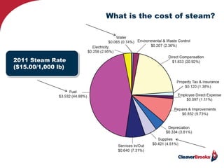
Boiler Condensate Return Basics
Presented by Steve Connor
February 24, 2016
What We Are Covering Today?
• Brief review of the total steam system
• Why a proper condensate return system is so important
• Condensate return and affect on the property’s operation
• What compromises the optimum condensate return system
• The corrective actions
• Delivering condensate back to the boiler room
• The choices for holding and treating this condensate.
• Summary
• Q/A
2
3
T
T
T
T
T
Steam
Condensate
H P Cond Return
Vent
D A TankD A Tank
Feed PumpBoiler
Strainer
Trap Trap
Trap Trap
TT
TT
DA
Tank
TT
TT
TTT
HP Steam
PRV
15 psig
250 F
LP Steam
150 psig
366 F
Trap
LP Condensate Return
Cond Recovery
& Pump
Motive
Force
Supply and Return System(s)
3
Legend
Water inlet
To drain
To drain
Total Boiler Room
4
Chemical feed
Water softener
Feed system
5
T
T
T
T
T
Steam
Condensate
H P Cond Return
Vent
D A TankD A Tank
Feed PumpBoiler
Strainer
Trap Trap
Trap Trap
TT
TT
DA
Tank
TT
TT
TTT
HP Steam
PRV
15 psig
250 F
LP Steam
150 psig
366 F
Trap
LP Condensate Return
Cond Recovery
& Pump
Motive
Force
Supply and Return System(s)
5
Legend
Reasons why condensate system is important
• Operating cost reduction
• Reliability
• Safety
Let’s first look at Efficiency & Cost of Operation
OK…
What is the cost of steam?
2011 Steam Rate
($15.00/1,000 lb)
Steam - Basic Concepts
2120 F.
2000 F.
1000 F.
320 F.
00 F.
138 880
Latent Heat
of Vaporization
(or Latent Heat
of Condensation)
Latent
Heat of
Fusion
Btu per pound of water
Sensible
Heat
Sensible
Heat
3380 F.
Boiler operating at 100 psig and 200 OF feed water
1 lb
water at
338O F
1 lb
steam at
338O F
1 lb
water at
200O F
9
Saturated Steam Table
Pressure
(psig)
0 10 80 100
Saturation
Temp
212 239.5 323.9 337.9
Volume (ft3/lb) 26.4 16.46 4.66 3.89
Sensible Heat
(btu/lb)
180 207.9 294.4 308.9
Latent Heat
(btu/lb)
970 952.5 891.9 880.7
Total Heat
(btu/lb)
1150 1160.4 1186.3 1189.4
Start @ 32 deg. F
10
FWT
30
Gauge Pressure - psig
40
70
80
60
140
100
150
110
50
130
90
160
170
180
120
190
200
212
220
227
230
29.0
29.3
30.1
30.4
29.8
32.1
30.9
32.4
31.2
29.6
31.8
30.6
32.7
33.0
33.4
31.5
33.8
34.1
34.5
34.8
35.0
35.2
29.0
29.2
30.0
30.3
29.8
32.0
30.8
32.4
31.2
29.5
31.7
30.6
32.7
33.0
33.3
31.4
33.7
34.0
34.4
34.7
34.9
35.0
28.8
29.1
29.9
30.1
29.6
31.8
30.6
32.1
30.9
29.3
31.5
30.4
32.4
32.7
33.0
31.2
33.4
33.7
34.2
34.4
34.7
34.8
28.7
29.0
29.8
30.0
29.5
31.7
30.6
32.0
30.8
29.2
31.4
30.3
32.4
32.6
33.0
32.2
33.3
33.6
34.1
34.3
34.5
34.7
28.6
29.4
29.7
29.1
31.4
30.2
31.6
30.5
28.9
31.1
30.0
31.9
32.3
32.6
30.8
32.9
33.2
33.5
33.0
34.2
34.4
34.5
28.4
29.2
29.5
28.9
31.1
30.0
31.4
30.3
28.7
30.8
29.8
31.7
32.0
32.3
30.6
32.6
32.9
33.2
33.6
33.9
34.1
34.2
28.3
29.1
29.4
28.8
31.0
29.9
31.3
30.2
28.6
30.7
29.6
31.6
31.9
32.2
30.4
32.5
32.8
33.1
33.5
33.8
34.0
34.1
28.2
29.0
29.3
28.8
30.9
29.8
31.2
30.1
28.5
30.6
29.6
31.5
31.8
32.1
30.3
32.4
32.7
33.0
33.4
33.7
33.9
34.0
28.2
28.9
29.2
28.7
30.8
29.7
31.1
30.0
28.4
30.5
29.5
31.4
31.7
32.0
30.2
32.3
32.6
32.9
33.3
33.5
33.8
33.9
28.1
28.8
29.1
28.6
30.7
29.6
31.0
29.8
28.3
30.4
29.3
31.2
31.5
31.8
30.0
32.2
32.5
32.8
33.2
33.4
33.7
33.8
28.0
28.8
29.0
28.5
30.6
29.5
30.9
29.8
28.2
30.3
29.2
31.2
31.4
31.7
30.0
32.1
32.4
32.7
33.1
33.3
33.6
33.7
28.0
28.7
29.0
28.5
30.6
29.5
30.8
29.8
28.2
30.3
29.2
31.2
31.4
31.7
30.0
32.0
32.4
32.6
33.0
33.3
33.5
33.6
27.9
28.7
28.9
28.4
30.5
29.4
30.8
29.7
28.2
30.2
29.2
31.1
31.4
31.7
30.0
32.0
32.3
32.6
33.0
33.2
33.5
33.6
27.9
28.6
28.9
28.4
30.5
29.4
30.8
29.7
28.2
30.2
29.2
31.1
31.4
31.6
30.0
32.0
32.3
32.6
33.0
33.2
33.4
33.5
27.9
28.6
28.9
28.4
30.4
29.4
30.8
29.7
28.2
30.2
29.1
31.0
31.3
31.6
29.9
31.9
32.2
32.6
32.9
33.1
33.4
33.5
27.9
28.6
28.8
28.3
30.4
29.3
30.7
29.6
28.1
30.1
29.1
31.0
31.3
31.6
29.9
31.9
32.2
32.5
32.9
33.1
33.3
33.4
27.9
28.6
28.8
28.3
30.4
29.3
30.7
29.6
28.1
30.1
29.1
30.9
31.2
31.5
29.8
31.8
32.1
32.4
32.8
33.1
33.3
33.4
0 2 10 15 20 40 50 60 80 100 120 140 150 160 180 200 220
27.8
28.5
28.8
28.3
30.4
29.3
30.6
29.6
28.1
30.1
29.0
30.9
31.2
31.5
29.8
31.8
32.1
32.4
32.8
33.0
33.3
33.4
240
Capacity At Operating Pressures vs. FWT
.
Energy Dollars at Risk
$
DOWN
THE
DRAIN
12
Every 10 degree drop in feed water
temperature equals a 1% drop in efficiency!
13
Blowdown Heat Recovery Types
Blowdown Heat Recovery Unit
• Proportional blowdown heat recovery system
• Atmospheric feed or deaerator
• Automatically controls TDS
• Single or Multiple Boilers
• Blowdown is cooled before discharge (Code compliance)
Condensate Recovery
Savings Derived from:
• Fuel savings
• Chemicals
• Water
• Sewer costs
Bringing back condensate at
higher pressures will result in
even greater savings!
Reliability Issues
Shell & Tube
Plate & FramePressure Regulating Valve
16
Jacketed Kettle
Split System
Condensate Back-up or “Stall”
17
Constant Orifice Purge
Steam Pump Trap
Steam power
pump
Vacuum breaker
Water leg
Vacuum breaker
Trap
NOTE: 2.3 feet of static head = 1 pound pressure
Air vent
Non Condensable Gas Corrosion
Courtesy:http://www.engineeringtoolbox.com/oxygen-steel-pipe-...
50 F
86 F
122 F
• Almost 2 times more
corrosive at 122o F
than at 86o F
• Dissolved oxygen is
10 times more
corrosive than CO2
CO2O2
23
Air and Corrosion
The Piping is Subject to Corrosion
Subcooled Condensate + CO2
Forms Carbonic Acid
( CO2 + H2O H2CO3 )
40% more corrosive when combined with dissolved O2!!
23
Carbonic Acid Corrosion
Cause and Effect
CO2 + H2O = H2CO3
• Created where
condensate is not
fully drained.
• Attacks pipe and
coil material.
25
Carbonic Acid attack
Cause and Effect
CO2 + H2O = H2CO3
25
Mechanical Chemical
26
Most Economical Long-Term Approach
27
Steam/Water Separator
Separation Mechanism
Cyclonic Type
• Cyclonic (centrifugal force)
• Baffle (directional flow change)
• Coalescence (trapping media) pad)
Secondary Steam Branch Line
In-line
separator
28To condensate return line
Drip pockets & Steam Trap Set
Isolation valves
Check valve
strainer
trap
Drip Pockets
Steam Trap
Drip Leg
6-10”
BD and Venting
Locations:
• Low Spots
• End of Main Ahead of
Expansion Joints
• Ahead of Valves,
Bends & Regulators
30
Locate every 150 – 300 feet in a linear length of steam pipe
31
Steam Main Size Drip Leg Diameter Drip leg Length
4” 4” 12”
6” 4” 12”
8” 4” 12”
10” 6” 18”
12” 6” 18”
14” 8” 24”
16” 8” 24”
18” 10” 30”
20” 10” 30”
24” 12” 36”
Suggested Sizing
31
Moving condensate from source to boiler room
Motive force of steam pressure differential
Condensate Transfer Tanks
• Standard models 200°F
or less
• 210°F floor mounted
units w/ low NPSH
pumps
• 212°F elevated units
available, thereby
increasing NPSH
Steam & Condensate Velocity
Typical Velocities in steam systems:
Process Piping 6000 – 8000 fpm
(70 – 90 MPH)
LP Heating
Systems
4000 – 6000 fpm
(45 – 70 MPH)
Typical Velocities in Condensate return
systems
Liquid 180 – 420 fpm
Bi-phase Approx. 3000-
7000 fpm
• Boiler operating pressure
• Pounds of condensate
• Pressure at trap inlet
• Pressure in line
• Condensate pipe diameter
• Allowable pressure drop
Note: Pressure drop should not exceed 20% of boiler’s maximum operating pressure
35
T
T
T
T
T
Steam
Condensate
Common Condensate Return
D A TankD A Tank
Feed PumpBoiler
Strainer
Trap Trap
Trap TrapTT
TT
DA
Tank
TT
TT
TTT
HP Steam LP Steam
150 psig
366 F
Motive
Force
Supply and Return System(s)
35
Legend
Trap
Saturated Steam Table
Pressure
(psig)
0 10 80 100
Saturation
Temp
212 239.5 323.9 337.9
Volume (ft3/lb) 26.4 16.46 4.66 3.89
Sensible Heat
(btu/lb)
180 207.9 294.4 308.9
Latent Heat
(btu/lb)
970 952.5 891.9 880.7
Total Heat
(btu/lb)
1150 1160.4 1186.3 1189.4
Start @ 32 deg. F
36
.017
Steam & Condensate Velocity
Typical Velocities in steam systems:
Process Piping 6000 – 8000 fpm
(70 – 90 MPH)
LP Heating Systems 4000 – 6000 fpm
(45 – 70 MPH)
Preferred Velocities in Condensate return systems
Liquid 180 – 420 fpm
Bi-phase Approx. 3000 - 7000 fpm
Condensate Pipe sizing
• Boiler operating pressure
• Pounds of condensate
• Pressure at trap inlet
• Pressure in line
• Condensate pipe diameter
• Allowable pressure drop
Condensate pipe sizing criteria
Example:
• 2000#/HR
• 7000 ft/min
• ¼# drop
• 150# inlet
• Zero & 15# outlet
And what’s the Safety Issue with condensate?
Efficiency
Reliability
Capture
Transportation
Cause & Effect of Water Hammer
Three Types of Water Hammer:
Hydraulic
Thermal
Differential
Thermal water hammer
The steam condensing void is rapidly filled with water
Thermal
Thermal Imaging & diffusion of condensate lines
Diffuser
43
Flash Tank
Flash Tank
• Higher temperature drip traps
• Vent to atmosphere
• Use flash steam for LP use (non-modulating)
• Preheat boiler feed water
Drip trap location
Steam User
44
Calculating Flash Steam %
Formula: (hf1 – hf2 )/hfg2 = % Flash
HF1: Sensible Btu’s in
HF2: Sensible Btu’s out
HFG2: Latent Btu’s out
Example: User operating at 150 psig with discharge @
15 psig…..
338 – 218 = 120/946 = 13% Flash Captured!
. Btu’s SAVED!
. Water & Sewer charges SAVED!
. Chemicals SAVED!
T
T
T
T
T
H P Condensate Return
Cond. Pump
D A TankD A Tank
Feed PumpBoiler
Strainer
Trap Trap
Trap Trap
TT
TT
TT
TT
TTT
HP Steam
PRV
15 psig
250 F
LP Steam
175 psig
366 F
Trap
Motive
Force
Feed Tank or
DA
HP Condensate Recovery
High Pressure Condensate Receiver
• Takes high pressure
condensate directly
from the user.
• No need to deaerate.
• Pump directly into
boiler
• Feed the HPR from
the DA
Holding the boiler’s feed water and protecting
the system
HOT Condensate returned
Deaerator
Boiler Feed System
A vented receiver, wastes energy.
48
Pressurized receiver, saves energy.
Steam diffusing tube
Chemical Feed Tank
49
• Phosphonates
• Chelant (de-scaler)
• Polymers
• Sulfite
• Non-sulfite scavengers
• Amines (neutralizing or filming)
Mixing and Dispensing
Final Summary
50
• The boiler is part of a total system including its piping supply and return
network, and all the associated accessories supporting the total whole.
• Proper condensate line engineering impacts energy efficiency,
production reliability, and safety
• Every 10 degree pickup in feedwater temperature = 1% fuel savings
• Condensate is sensible energy which increases with increasing
operating pressures
• Reliability is affected by system backup (Stall) and system corrosion
• Condensate line water hammer is normally Thermal type
• Flash recovery systems can mitigate problem and save energy
• Recommended velocities in bi-phase condensate lines is 3000 – 7000
ft/min
• As line pressure in bi-phase condensate increases the volume
decreases, reducing line size for same velocity.
• Condensate line sizing involves knowing boiler pressure, trap inlet
pressure, pounds of condensate, common line pressure, desired
velocity, and desired pressure drop
Steve Connor
Training & Technical Consultant
• sconnor@cleaverbrooks.com
• www.cleaverbrooks.com
51

Feb. 2016 webinar_condensate_return_piping

  • 1.
    Boiler Condensate ReturnBasics Presented by Steve Connor February 24, 2016
  • 2.
    What We AreCovering Today? • Brief review of the total steam system • Why a proper condensate return system is so important • Condensate return and affect on the property’s operation • What compromises the optimum condensate return system • The corrective actions • Delivering condensate back to the boiler room • The choices for holding and treating this condensate. • Summary • Q/A 2
  • 3.
    3 T T T T T Steam Condensate H P CondReturn Vent D A TankD A Tank Feed PumpBoiler Strainer Trap Trap Trap Trap TT TT DA Tank TT TT TTT HP Steam PRV 15 psig 250 F LP Steam 150 psig 366 F Trap LP Condensate Return Cond Recovery & Pump Motive Force Supply and Return System(s) 3 Legend
  • 4.
    Water inlet To drain Todrain Total Boiler Room 4 Chemical feed Water softener Feed system
  • 5.
    5 T T T T T Steam Condensate H P CondReturn Vent D A TankD A Tank Feed PumpBoiler Strainer Trap Trap Trap Trap TT TT DA Tank TT TT TTT HP Steam PRV 15 psig 250 F LP Steam 150 psig 366 F Trap LP Condensate Return Cond Recovery & Pump Motive Force Supply and Return System(s) 5 Legend
  • 6.
    Reasons why condensatesystem is important • Operating cost reduction • Reliability • Safety
  • 7.
    Let’s first lookat Efficiency & Cost of Operation OK…
  • 8.
    What is thecost of steam? 2011 Steam Rate ($15.00/1,000 lb)
  • 9.
    Steam - BasicConcepts 2120 F. 2000 F. 1000 F. 320 F. 00 F. 138 880 Latent Heat of Vaporization (or Latent Heat of Condensation) Latent Heat of Fusion Btu per pound of water Sensible Heat Sensible Heat 3380 F. Boiler operating at 100 psig and 200 OF feed water 1 lb water at 338O F 1 lb steam at 338O F 1 lb water at 200O F 9
  • 10.
    Saturated Steam Table Pressure (psig) 010 80 100 Saturation Temp 212 239.5 323.9 337.9 Volume (ft3/lb) 26.4 16.46 4.66 3.89 Sensible Heat (btu/lb) 180 207.9 294.4 308.9 Latent Heat (btu/lb) 970 952.5 891.9 880.7 Total Heat (btu/lb) 1150 1160.4 1186.3 1189.4 Start @ 32 deg. F 10
  • 11.
    FWT 30 Gauge Pressure -psig 40 70 80 60 140 100 150 110 50 130 90 160 170 180 120 190 200 212 220 227 230 29.0 29.3 30.1 30.4 29.8 32.1 30.9 32.4 31.2 29.6 31.8 30.6 32.7 33.0 33.4 31.5 33.8 34.1 34.5 34.8 35.0 35.2 29.0 29.2 30.0 30.3 29.8 32.0 30.8 32.4 31.2 29.5 31.7 30.6 32.7 33.0 33.3 31.4 33.7 34.0 34.4 34.7 34.9 35.0 28.8 29.1 29.9 30.1 29.6 31.8 30.6 32.1 30.9 29.3 31.5 30.4 32.4 32.7 33.0 31.2 33.4 33.7 34.2 34.4 34.7 34.8 28.7 29.0 29.8 30.0 29.5 31.7 30.6 32.0 30.8 29.2 31.4 30.3 32.4 32.6 33.0 32.2 33.3 33.6 34.1 34.3 34.5 34.7 28.6 29.4 29.7 29.1 31.4 30.2 31.6 30.5 28.9 31.1 30.0 31.9 32.3 32.6 30.8 32.9 33.2 33.5 33.0 34.2 34.4 34.5 28.4 29.2 29.5 28.9 31.1 30.0 31.4 30.3 28.7 30.8 29.8 31.7 32.0 32.3 30.6 32.6 32.9 33.2 33.6 33.9 34.1 34.2 28.3 29.1 29.4 28.8 31.0 29.9 31.3 30.2 28.6 30.7 29.6 31.6 31.9 32.2 30.4 32.5 32.8 33.1 33.5 33.8 34.0 34.1 28.2 29.0 29.3 28.8 30.9 29.8 31.2 30.1 28.5 30.6 29.6 31.5 31.8 32.1 30.3 32.4 32.7 33.0 33.4 33.7 33.9 34.0 28.2 28.9 29.2 28.7 30.8 29.7 31.1 30.0 28.4 30.5 29.5 31.4 31.7 32.0 30.2 32.3 32.6 32.9 33.3 33.5 33.8 33.9 28.1 28.8 29.1 28.6 30.7 29.6 31.0 29.8 28.3 30.4 29.3 31.2 31.5 31.8 30.0 32.2 32.5 32.8 33.2 33.4 33.7 33.8 28.0 28.8 29.0 28.5 30.6 29.5 30.9 29.8 28.2 30.3 29.2 31.2 31.4 31.7 30.0 32.1 32.4 32.7 33.1 33.3 33.6 33.7 28.0 28.7 29.0 28.5 30.6 29.5 30.8 29.8 28.2 30.3 29.2 31.2 31.4 31.7 30.0 32.0 32.4 32.6 33.0 33.3 33.5 33.6 27.9 28.7 28.9 28.4 30.5 29.4 30.8 29.7 28.2 30.2 29.2 31.1 31.4 31.7 30.0 32.0 32.3 32.6 33.0 33.2 33.5 33.6 27.9 28.6 28.9 28.4 30.5 29.4 30.8 29.7 28.2 30.2 29.2 31.1 31.4 31.6 30.0 32.0 32.3 32.6 33.0 33.2 33.4 33.5 27.9 28.6 28.9 28.4 30.4 29.4 30.8 29.7 28.2 30.2 29.1 31.0 31.3 31.6 29.9 31.9 32.2 32.6 32.9 33.1 33.4 33.5 27.9 28.6 28.8 28.3 30.4 29.3 30.7 29.6 28.1 30.1 29.1 31.0 31.3 31.6 29.9 31.9 32.2 32.5 32.9 33.1 33.3 33.4 27.9 28.6 28.8 28.3 30.4 29.3 30.7 29.6 28.1 30.1 29.1 30.9 31.2 31.5 29.8 31.8 32.1 32.4 32.8 33.1 33.3 33.4 0 2 10 15 20 40 50 60 80 100 120 140 150 160 180 200 220 27.8 28.5 28.8 28.3 30.4 29.3 30.6 29.6 28.1 30.1 29.0 30.9 31.2 31.5 29.8 31.8 32.1 32.4 32.8 33.0 33.3 33.4 240 Capacity At Operating Pressures vs. FWT .
  • 12.
    Energy Dollars atRisk $ DOWN THE DRAIN 12 Every 10 degree drop in feed water temperature equals a 1% drop in efficiency!
  • 13.
    13 Blowdown Heat RecoveryTypes Blowdown Heat Recovery Unit • Proportional blowdown heat recovery system • Atmospheric feed or deaerator • Automatically controls TDS • Single or Multiple Boilers • Blowdown is cooled before discharge (Code compliance)
  • 14.
    Condensate Recovery Savings Derivedfrom: • Fuel savings • Chemicals • Water • Sewer costs Bringing back condensate at higher pressures will result in even greater savings!
  • 15.
  • 16.
    Shell & Tube Plate& FramePressure Regulating Valve 16 Jacketed Kettle Split System
  • 17.
    Condensate Back-up or“Stall” 17
  • 18.
  • 19.
  • 20.
    Vacuum breaker Water leg Vacuumbreaker Trap NOTE: 2.3 feet of static head = 1 pound pressure
  • 21.
  • 22.
    Non Condensable GasCorrosion Courtesy:http://www.engineeringtoolbox.com/oxygen-steel-pipe-... 50 F 86 F 122 F • Almost 2 times more corrosive at 122o F than at 86o F • Dissolved oxygen is 10 times more corrosive than CO2 CO2O2
  • 23.
    23 Air and Corrosion ThePiping is Subject to Corrosion Subcooled Condensate + CO2 Forms Carbonic Acid ( CO2 + H2O H2CO3 ) 40% more corrosive when combined with dissolved O2!! 23
  • 24.
    Carbonic Acid Corrosion Causeand Effect CO2 + H2O = H2CO3 • Created where condensate is not fully drained. • Attacks pipe and coil material.
  • 25.
    25 Carbonic Acid attack Causeand Effect CO2 + H2O = H2CO3 25
  • 26.
  • 27.
    27 Steam/Water Separator Separation Mechanism CyclonicType • Cyclonic (centrifugal force) • Baffle (directional flow change) • Coalescence (trapping media) pad)
  • 28.
    Secondary Steam BranchLine In-line separator 28To condensate return line
  • 29.
    Drip pockets &Steam Trap Set Isolation valves Check valve strainer trap
  • 30.
    Drip Pockets Steam Trap DripLeg 6-10” BD and Venting Locations: • Low Spots • End of Main Ahead of Expansion Joints • Ahead of Valves, Bends & Regulators 30 Locate every 150 – 300 feet in a linear length of steam pipe
  • 31.
    31 Steam Main SizeDrip Leg Diameter Drip leg Length 4” 4” 12” 6” 4” 12” 8” 4” 12” 10” 6” 18” 12” 6” 18” 14” 8” 24” 16” 8” 24” 18” 10” 30” 20” 10” 30” 24” 12” 36” Suggested Sizing 31
  • 32.
    Moving condensate fromsource to boiler room Motive force of steam pressure differential
  • 33.
    Condensate Transfer Tanks •Standard models 200°F or less • 210°F floor mounted units w/ low NPSH pumps • 212°F elevated units available, thereby increasing NPSH
  • 34.
    Steam & CondensateVelocity Typical Velocities in steam systems: Process Piping 6000 – 8000 fpm (70 – 90 MPH) LP Heating Systems 4000 – 6000 fpm (45 – 70 MPH) Typical Velocities in Condensate return systems Liquid 180 – 420 fpm Bi-phase Approx. 3000- 7000 fpm • Boiler operating pressure • Pounds of condensate • Pressure at trap inlet • Pressure in line • Condensate pipe diameter • Allowable pressure drop Note: Pressure drop should not exceed 20% of boiler’s maximum operating pressure
  • 35.
    35 T T T T T Steam Condensate Common Condensate Return DA TankD A Tank Feed PumpBoiler Strainer Trap Trap Trap TrapTT TT DA Tank TT TT TTT HP Steam LP Steam 150 psig 366 F Motive Force Supply and Return System(s) 35 Legend Trap
  • 36.
    Saturated Steam Table Pressure (psig) 010 80 100 Saturation Temp 212 239.5 323.9 337.9 Volume (ft3/lb) 26.4 16.46 4.66 3.89 Sensible Heat (btu/lb) 180 207.9 294.4 308.9 Latent Heat (btu/lb) 970 952.5 891.9 880.7 Total Heat (btu/lb) 1150 1160.4 1186.3 1189.4 Start @ 32 deg. F 36 .017
  • 37.
    Steam & CondensateVelocity Typical Velocities in steam systems: Process Piping 6000 – 8000 fpm (70 – 90 MPH) LP Heating Systems 4000 – 6000 fpm (45 – 70 MPH) Preferred Velocities in Condensate return systems Liquid 180 – 420 fpm Bi-phase Approx. 3000 - 7000 fpm
  • 38.
    Condensate Pipe sizing •Boiler operating pressure • Pounds of condensate • Pressure at trap inlet • Pressure in line • Condensate pipe diameter • Allowable pressure drop Condensate pipe sizing criteria Example: • 2000#/HR • 7000 ft/min • ¼# drop • 150# inlet • Zero & 15# outlet
  • 39.
    And what’s theSafety Issue with condensate? Efficiency Reliability Capture Transportation
  • 40.
    Cause & Effectof Water Hammer Three Types of Water Hammer: Hydraulic Thermal Differential
  • 41.
    Thermal water hammer Thesteam condensing void is rapidly filled with water Thermal
  • 42.
    Thermal Imaging &diffusion of condensate lines Diffuser
  • 43.
    43 Flash Tank Flash Tank •Higher temperature drip traps • Vent to atmosphere • Use flash steam for LP use (non-modulating) • Preheat boiler feed water Drip trap location Steam User
  • 44.
    44 Calculating Flash Steam% Formula: (hf1 – hf2 )/hfg2 = % Flash HF1: Sensible Btu’s in HF2: Sensible Btu’s out HFG2: Latent Btu’s out Example: User operating at 150 psig with discharge @ 15 psig….. 338 – 218 = 120/946 = 13% Flash Captured! . Btu’s SAVED! . Water & Sewer charges SAVED! . Chemicals SAVED!
  • 45.
    T T T T T H P CondensateReturn Cond. Pump D A TankD A Tank Feed PumpBoiler Strainer Trap Trap Trap Trap TT TT TT TT TTT HP Steam PRV 15 psig 250 F LP Steam 175 psig 366 F Trap Motive Force Feed Tank or DA HP Condensate Recovery
  • 46.
    High Pressure CondensateReceiver • Takes high pressure condensate directly from the user. • No need to deaerate. • Pump directly into boiler • Feed the HPR from the DA
  • 47.
    Holding the boiler’sfeed water and protecting the system
  • 48.
    HOT Condensate returned Deaerator BoilerFeed System A vented receiver, wastes energy. 48 Pressurized receiver, saves energy. Steam diffusing tube
  • 49.
    Chemical Feed Tank 49 •Phosphonates • Chelant (de-scaler) • Polymers • Sulfite • Non-sulfite scavengers • Amines (neutralizing or filming) Mixing and Dispensing
  • 50.
    Final Summary 50 • Theboiler is part of a total system including its piping supply and return network, and all the associated accessories supporting the total whole. • Proper condensate line engineering impacts energy efficiency, production reliability, and safety • Every 10 degree pickup in feedwater temperature = 1% fuel savings • Condensate is sensible energy which increases with increasing operating pressures • Reliability is affected by system backup (Stall) and system corrosion • Condensate line water hammer is normally Thermal type • Flash recovery systems can mitigate problem and save energy • Recommended velocities in bi-phase condensate lines is 3000 – 7000 ft/min • As line pressure in bi-phase condensate increases the volume decreases, reducing line size for same velocity. • Condensate line sizing involves knowing boiler pressure, trap inlet pressure, pounds of condensate, common line pressure, desired velocity, and desired pressure drop
  • 51.
    Steve Connor Training &Technical Consultant • sconnor@cleaverbrooks.com • www.cleaverbrooks.com 51