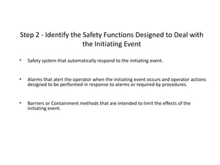
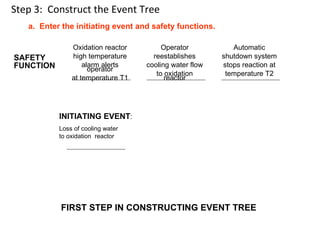
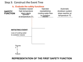
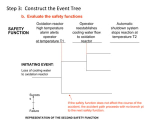
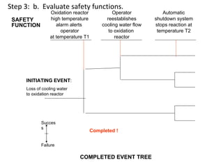
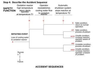
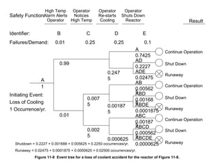
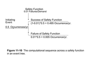
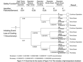
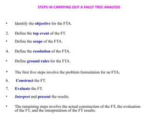
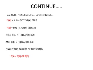
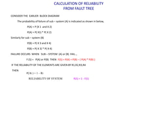
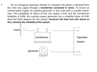
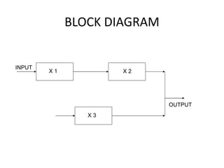
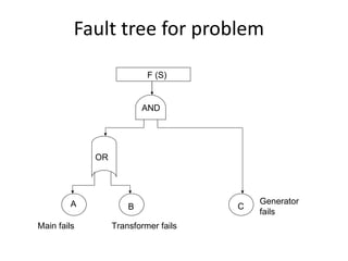
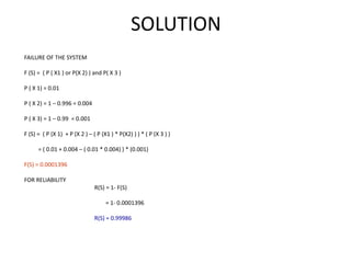
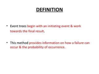
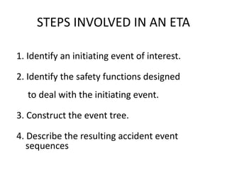
Fault tree analysis (FTA) and event tree analysis (ETA) are probabilistic risk assessment techniques. [FTA] works backwards from an accident to identify causes, representing them in a logic diagram with gates and basic events. [ETA] works forwards from an initiating event through safety functions to outcomes. The document outlines the steps and uses of FTA and ETA, providing examples to illustrate fault tree and event tree construction and accident sequence description.

![Step 1 - Identify the initiating event
• system or equipment failure
• human error
• process upset
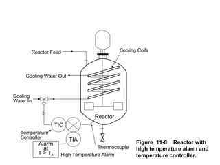
[Example]
“Loss of Cooling Water”
to an Oxidation Reactor](https://image.slidesharecdn.com/nitesh-120410080750-phpapp01/85/FAULT-EVENT-TREE-ANALYSIS-22-320.jpg)