Download to read offline
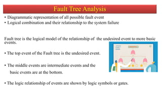
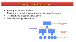
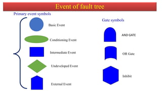
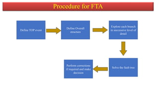


The document discusses fault tree analysis (FTA), which uses logic diagrams to identify the causes of failures in complex systems. FTA breaks down an undesired event into a logical combination of intermediate and basic events. The document provides an example of constructing a fault tree to calculate the expected frequency of injury to a steam boiler operator based on failure rates of components like water level detectors, pressure switches, and relief valves.